EP1921430B1 - Procédé destiné à la détermination de la température régnant sur un capteur à particules résistives - Google Patents
Procédé destiné à la détermination de la température régnant sur un capteur à particules résistives Download PDFInfo
- Publication number
- EP1921430B1 EP1921430B1 EP07117514.5A EP07117514A EP1921430B1 EP 1921430 B1 EP1921430 B1 EP 1921430B1 EP 07117514 A EP07117514 A EP 07117514A EP 1921430 B1 EP1921430 B1 EP 1921430B1
- Authority
- EP
- European Patent Office
- Prior art keywords
- temperature
- particle sensor
- heating device
- sensor
- operated
- Prior art date
- Legal status (The legal status is an assumption and is not a legal conclusion. Google has not performed a legal analysis and makes no representation as to the accuracy of the status listed.)
- Ceased
Links
- 239000002245 particle Substances 0.000 title claims description 37
- 238000000034 method Methods 0.000 title claims description 18
- 238000010438 heat treatment Methods 0.000 claims description 28
- 239000004071 soot Substances 0.000 claims description 7
- 230000002596 correlated effect Effects 0.000 claims description 4
- 238000005259 measurement Methods 0.000 claims description 4
- BASFCYQUMIYNBI-UHFFFAOYSA-N platinum Chemical group [Pt] BASFCYQUMIYNBI-UHFFFAOYSA-N 0.000 claims description 4
- 238000012417 linear regression Methods 0.000 claims description 3
- 230000000712 assembly Effects 0.000 claims description 2
- 238000000429 assembly Methods 0.000 claims description 2
- 229910052697 platinum Inorganic materials 0.000 claims description 2
- 230000008901 benefit Effects 0.000 description 4
- 238000001816 cooling Methods 0.000 description 4
- 238000013461 design Methods 0.000 description 3
- 238000004519 manufacturing process Methods 0.000 description 3
- 230000032683 aging Effects 0.000 description 2
- 230000007423 decrease Effects 0.000 description 2
- 230000003247 decreasing effect Effects 0.000 description 2
- 230000001419 dependent effect Effects 0.000 description 2
- 230000008021 deposition Effects 0.000 description 2
- 238000011161 development Methods 0.000 description 2
- 230000018109 developmental process Effects 0.000 description 2
- 238000009413 insulation Methods 0.000 description 2
- 230000000737 periodic effect Effects 0.000 description 2
- 230000005855 radiation Effects 0.000 description 2
- 230000008929 regeneration Effects 0.000 description 2
- 238000011069 regeneration method Methods 0.000 description 2
- XLYOFNOQVPJJNP-UHFFFAOYSA-N water Substances O XLYOFNOQVPJJNP-UHFFFAOYSA-N 0.000 description 2
- 238000009529 body temperature measurement Methods 0.000 description 1
- 239000000919 ceramic Substances 0.000 description 1
- 238000002485 combustion reaction Methods 0.000 description 1
- 238000009833 condensation Methods 0.000 description 1
- 230000005494 condensation Effects 0.000 description 1
- 230000003292 diminished effect Effects 0.000 description 1
- 230000002349 favourable effect Effects 0.000 description 1
- 239000012530 fluid Substances 0.000 description 1
- 229930195733 hydrocarbon Natural products 0.000 description 1
- 150000002430 hydrocarbons Chemical class 0.000 description 1
- 230000007774 longterm Effects 0.000 description 1
- 238000012545 processing Methods 0.000 description 1
- 230000000284 resting effect Effects 0.000 description 1
- 238000004092 self-diagnosis Methods 0.000 description 1
- 230000035945 sensitivity Effects 0.000 description 1
- 210000002023 somite Anatomy 0.000 description 1
- 239000000126 substance Substances 0.000 description 1
- 239000000758 substrate Substances 0.000 description 1
Images
Classifications
-
- G—PHYSICS
- G01—MEASURING; TESTING
- G01K—MEASURING TEMPERATURE; MEASURING QUANTITY OF HEAT; THERMALLY-SENSITIVE ELEMENTS NOT OTHERWISE PROVIDED FOR
- G01K7/00—Measuring temperature based on the use of electric or magnetic elements directly sensitive to heat ; Power supply therefor, e.g. using thermoelectric elements
- G01K7/16—Measuring temperature based on the use of electric or magnetic elements directly sensitive to heat ; Power supply therefor, e.g. using thermoelectric elements using resistive elements
- G01K7/18—Measuring temperature based on the use of electric or magnetic elements directly sensitive to heat ; Power supply therefor, e.g. using thermoelectric elements using resistive elements the element being a linear resistance, e.g. platinum resistance thermometer
-
- G—PHYSICS
- G01—MEASURING; TESTING
- G01N—INVESTIGATING OR ANALYSING MATERIALS BY DETERMINING THEIR CHEMICAL OR PHYSICAL PROPERTIES
- G01N15/00—Investigating characteristics of particles; Investigating permeability, pore-volume or surface-area of porous materials
- G01N15/06—Investigating concentration of particle suspensions
- G01N15/0656—Investigating concentration of particle suspensions using electric, e.g. electrostatic methods or magnetic methods
-
- G—PHYSICS
- G01—MEASURING; TESTING
- G01K—MEASURING TEMPERATURE; MEASURING QUANTITY OF HEAT; THERMALLY-SENSITIVE ELEMENTS NOT OTHERWISE PROVIDED FOR
- G01K2205/00—Application of thermometers in motors, e.g. of a vehicle
- G01K2205/04—Application of thermometers in motors, e.g. of a vehicle for measuring exhaust gas temperature
Definitions
- the invention is based on a method for determining the temperature prevailing at a resistive particle sensor and a resistive particle sensor operated by a method according to the type defined in the preamble of the independent claims.
- resistive particle sensors for conductive particles in which two or more metallic electrodes are formed, wherein the accumulating particles, in particular soot particles, which preferably short comb-like interdigitated electrodes and thus with decreasing particle concentration on the sensor surfaces, a decreasing resistance between the electrodes measurable becomes.
- a sensor for detecting particles in a fluid stream which is carried out on the basis of a ceramic multilayer substrate. It comprises two spaced-apart measuring electrodes, which are exposed to the combustion exhaust gas to be examined. If soot is deposited between the two measuring electrodes, a current flow between the measuring electrodes occurs when a voltage is applied to the measuring electrodes.
- a layered heating element makes it possible to free the electrodes or their surroundings by thermal means from deposited soot particles.
- the sensor further comprises a temperature measuring element with which the temperature of the sensor can be detected. The heating element is located within the laminate of the sensor between the temperature measuring element and the measuring electrodes.
- the sensor signal To determine the particle concentration in the exhaust gas, the sensor signal must be compensated for various cross influences. Among other things, knowledge of the temperature of the sensor element is necessary for this compensation.
- a conventional particle sensor currently requires 4 to 5 connection cables. However, the production and the adjustment of the separate temperature measuring meander in the sensor element are a significant cost component of the total sensor.
- the heating element mentioned in step a) expediently comprises a platinum heating element.
- a PTC element ie a heating element with a positive temperature coefficient of electrical resistance.
- the model-based temperature mentioned in step b) can originate from a temperature model of the engine and of the exhaust gas line. For example, from the knowledge of engine speed, engine load, heat capacity and radiation behavior of these assemblies can be indirectly closed to the temperature prevailing at the particle sensor itself.
- the correlation of the electrical resistance of the heating element R H with the model-based temperature T M determined in step c) at the time of the measurement of R H can be done as a linear regression.
- R H may represent the x-axis and T M the y-axis.
- T M the y-axis.
- T M R H mR H + b with m as the slope of the line and b as the ordinate section.
- step e a temperature T prevailing at the particle sensor is calculated from the values obtained in the previous step by the compensation function.
- the constant R 0 in turn can be determined from defined points of the compensation function via the ordinate section b.
- An added benefit of the method according to the invention is the possibility of detecting aging of the heating element by following the change in the specific constants ⁇ and R 0 .
- the drift / aging can be quantified. For example, when determining the last 100, 200 or 1000 data sets can be averaged. This also makes it possible to adapt the heating power required for full regeneration of the sensor over the life of the sensor.
- Another added benefit can be achieved by detecting a drift in the intrinsic conductivity of the insulation layer system below the electrode system in the particle sensor.
- a self-diagnosis concept of a resistive particle sensor it is possible to determine the intrinsic conductivity of the insulation layers below the electrode system during a regeneration phase and thus determine the integrity of the electrode.
- the drift of the temperature-dependent intrinsic conductivity of the insulating layer can be better measured and corrected if necessary in a control unit.
- the heating device is operated constantly at a temperature of ⁇ 100 ° C to ⁇ 500 ° C, preferably 200 ° C to ⁇ 450 ° C, more preferably 300 ° C to ⁇ 400 ° C ,
- the term "constant" is understood to mean that the temperature does not fluctuate by more than 10% by a predetermined value.
- the specified temperature is below the temperature at which the soot particle layer burns on the electrode surface. In this way, the actual variation of the temperature of the particle layer can be reduced, whose temperature dependence of its electrical conductivity can be a source of inaccuracy in the determination of the amount of particles on the measuring electrodes.
- this mode of operation has the advantage of preventing the condensation of water, hydrocarbons or other substances on the measuring electrodes of the particle sensor. Since the thermophoretic deposition makes up only a small proportion of the deposition of the particles on the measuring electrodes, the sensitivity of the sensor is not diminished thereby.
- the electrical power P H recorded by the heater is additionally measured after step b) and also correlated with R H and T M in step c).
- P H is measured during a self-heated state of the particulate sensor. This gives a three-dimensional point cloud with measured values.
- the data sets can be analyzed by multidimensional linear regression.
- a plane is placed in the P H / R H / T M space and the squares of the deviations of the T M values are minimized.
- the absorbed electrical power P H is included, it is also possible to include the cooling or heating of the sensor element depending on the flow through the exhaust gas. A model state that predicts an inaccurate temperature due to a high flow is now better balanced.
- R H R 0 1 + a 1 P H + a 2 P H 2 + ... - b 1 v gas - b 2 v gas 2 - ...
- the constants b 1 , b 2 , etc. result from the cooling behavior and the geometry of the sensor element. From this relationship, therefore, the exhaust gas velocity v gas can be determined over the sensor element. Since, however, this exhaust gas velocity is in a fixed, design-dependent relationship to the exhaust gas velocity in the entire exhaust gas pipe, an adjustment of the gas velocity from the parameters of the model of the engine can take place. It should be noted that when the heater is switched on, as described above, the exhaust gas velocity can be determined and with the heater off, the temperature prevailing at the particle sensor.
- the heating device is periodically at a temperature of ⁇ 100 ° C to ⁇ 500 ° C, preferably from ⁇ 200 ° C to ⁇ 450 ° C, more preferably from ⁇ 300 ° C to ⁇ 400 ° C. operated.
- the term "periodic" here is to be understood that at regular intervals for a certain period of time, the heater is operated.
- the regular intervals can be for example 1, 2, 10 or 60 seconds.
- the duration of operation of the heater may be, for example, 1, 2 or 10 seconds.
- Such a periodic operation is advantageous when the driving situation changes little, since a large amount of data for determining the temperature and the exhaust gas velocity can be obtained with simultaneously limited storage capacity of the downstream data processing systems.
- the heating device is stochastically at a temperature of ⁇ 100 ° C to ⁇ 500 ° C, preferably from ⁇ 200 ° C to ⁇ 450 ° C, more preferably from ⁇ 300 ° C to ⁇ 400 ° C. operated.
- the term "stochastic" is understood to mean that the heater is operated at random intervals for a random period of time. Such stochastic operation is advantageous when the driving situation changes greatly. Due to the random operation of the heater, the temperature and the exhaust gas velocity are determined at equally random intervals. Thus, a more representative record of the varying driving conditions can be obtained.
- the heating device is operated at a temperature of ⁇ 500 ° C to ⁇ 1000 ° C, preferably from ⁇ 600 ° C to ⁇ 900 ° C, more preferably from ⁇ 700 ° C to ⁇ 800 ° C , This temperature is above the temperature at which the soot particle layer burns on the electrode surface. Operation at these temperatures makes it possible to determine the exhaust gas velocity very precisely, as already described above.
- the present invention furthermore relates to a resistive particle sensor operated by a method according to the present invention.
- Such a sensor is characterized by a simplified structure and a cheaper production.
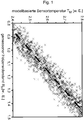
- FIG. 1 shows a correlation between the measured electrical resistance of the heating element R H (in arbitrary units) and the model-based sensor temperature T M (in arbitrary units). Due to variations in the production of the sensor element and in the measurements, a point cloud results, through which an equalization line can be laid (dashed line). During operation, the best-fit line can be determined with greater and better accuracy. By means of the method according to the invention, the respective errors of the measuring methods can cancel each other out.
- R H is measured with some scattering; T M from the temperature model helps here.
- T M is in some places of the temperature model in particular driving conditions inaccurate; Here, R H helps despite the scatter, as always in this driving condition, the inaccurate temperature of the model occurs.
Landscapes
- Physics & Mathematics (AREA)
- General Physics & Mathematics (AREA)
- Chemical & Material Sciences (AREA)
- Dispersion Chemistry (AREA)
- Health & Medical Sciences (AREA)
- Life Sciences & Earth Sciences (AREA)
- Analytical Chemistry (AREA)
- Biochemistry (AREA)
- General Health & Medical Sciences (AREA)
- Immunology (AREA)
- Pathology (AREA)
- Investigating Or Analyzing Materials By The Use Of Electric Means (AREA)
Claims (6)
- Procédé destiné à la détermination de la température régnant sur un capteur à particules résistif pour particules de suie qui est exposé à un gaz d'échappement,
dans lequel le capteur de particules résistif comprend un dispositif de chauffage, comprenant les étapes consistant à :a) mesurer la résistance électrique d'un élément chauffant RH, dans lequel l'élément chauffant est un élément PCT en platine présentant un coefficient de température positif de la résistance électrique,b) déterminer une température TM à base de modèle qui provient d'un modèle de température d'un moteur et d'un circuit de gaz d'échappement, au moyen duquel la température régnant sur le capteur de particules lui-même peut être indirectement déduite de la connaissance du régime du moteur, de la charge du moteur, de la capacité thermique et du comportement au rayonnement de ces ensembles,c) corréler au moyen d'une régression linéaire la résistance RH avec la température TM déterminée au moment de la mesure de l'humidité relative RH, de manière à ce qu'un nuage de points de valeurs de mesure corrélées se forme à mesure que le temps de mesure progresse,d) calculer une fonction de compensation à partir d'un ensemble de points de données obtenus à l'étape c) à différentes températures TM, dans lequel la fonction de compensation est une équation linéaire entre la température TM et la résistance RH, qui peut être déterminée au cours du fonctionnement du capteur de particules pour particules de suie avec une précision toujours plus grande,e) calculer une température de capteur T à partir des valeurs obtenues à l'étape d) dans la fonction de compensation. - Procédé selon la revendication 1, dans lequel le dispositif de chauffage fonctionne constamment à une température de ≥ 100 °C à ≤ 500 °C, de préférence de ≥ 200 °C à ≤ 450 °C, et plus préférentiellement de ≥ 300 °C à ≤ 400 °C.
- Procédé selon la revendication 1, dans lequel, après l'étape b), la puissance électrique PH consommée par le dispositif de chauffage est en outre mesurée et est également corrélée avec RH et TM à l'étape c).
- Procédé selon la revendication 3, dans lequel le dispositif de chauffage est utilisé périodiquement à une température de ≥ 100 °C à ≤ 500 °C, de préférence de ≥ 200 °C à ≤ 450 °C, et plus préférentiellement de ≥ 300 °C à ≤ 400 °C.
- Procédé selon la revendication 3, dans lequel le dispositif de chauffage est utilisé de manière stochastique à une température de ≥ 100 °C à ≤ 500 °C, de préférence de ≥ 200 °C à ≤ 450 °C, et plus préférentiellement de ≥ 300 °C à ≤ 400 °C.
- Procédé selon la revendication 3, dans lequel le dispositif de chauffage est utilisé à une température de ≥ 500 °C à ≤ 1000 °C, de préférence de ≥ 600 °C à ≤ 900 °C, et plus préférentiellement de ≥ 700 °C à ≤ 800 °C.
Applications Claiming Priority (1)
| Application Number | Priority Date | Filing Date | Title |
|---|---|---|---|
| DE200610053100 DE102006053100A1 (de) | 2006-11-10 | 2006-11-10 | Verfahren zur Bestimmung der an einem resistiven Partikelsensor herrschenden Temperatur |
Publications (2)
| Publication Number | Publication Date |
|---|---|
| EP1921430A1 EP1921430A1 (fr) | 2008-05-14 |
| EP1921430B1 true EP1921430B1 (fr) | 2019-03-27 |
Family
ID=38961084
Family Applications (1)
| Application Number | Title | Priority Date | Filing Date |
|---|---|---|---|
| EP07117514.5A Ceased EP1921430B1 (fr) | 2006-11-10 | 2007-09-28 | Procédé destiné à la détermination de la température régnant sur un capteur à particules résistives |
Country Status (2)
| Country | Link |
|---|---|
| EP (1) | EP1921430B1 (fr) |
| DE (1) | DE102006053100A1 (fr) |
Families Citing this family (9)
| Publication number | Priority date | Publication date | Assignee | Title |
|---|---|---|---|---|
| DE102009028239B4 (de) | 2009-08-05 | 2026-03-26 | Robert Bosch Gmbh | Verfahren zur Eigendiagnose eines Partikelsensors |
| DE102009049669A1 (de) * | 2009-10-16 | 2011-04-21 | Continental Automotive Gmbh | Verfahren zur Zustandsbewertung eines Rußsensors in einem Kraftfahrzeug |
| JP5115873B2 (ja) | 2010-12-08 | 2013-01-09 | 株式会社デンソー | パティキュレートフィルタの故障検出装置 |
| JP5240679B2 (ja) | 2011-01-20 | 2013-07-17 | 株式会社デンソー | 検出装置 |
| EP2492481A1 (fr) * | 2011-02-22 | 2012-08-29 | Delphi Technologies Holding S.à.r.l. | Surveillance de capacité fonctionnelle de capteur de suie |
| US10240984B2 (en) | 2012-03-28 | 2019-03-26 | Delphi Technologies, Inc. | Temperature measurement method for a heated sensor |
| US9334773B2 (en) * | 2013-10-31 | 2016-05-10 | Cummins Ip, Inc. | Particulate matter sensor regeneration |
| US9234805B2 (en) | 2013-10-31 | 2016-01-12 | Cummins Ip, Inc. | Temperature compensation for particulate matter sensor regeneration |
| DE102022203057A1 (de) * | 2022-03-29 | 2023-10-05 | Robert Bosch Gesellschaft mit beschränkter Haftung | Verfahren zum Betreiben eines Sensors zur Erfassung mindestens einer Eigenschaft eines Messgases |
Family Cites Families (5)
| Publication number | Priority date | Publication date | Assignee | Title |
|---|---|---|---|---|
| US5345213A (en) * | 1992-10-26 | 1994-09-06 | The United States Of America, As Represented By The Secretary Of Commerce | Temperature-controlled, micromachined arrays for chemical sensor fabrication and operation |
| US5918263A (en) * | 1998-03-31 | 1999-06-29 | Lockheed Martin Energy Research Corporation | Microcantilever detector for explosives |
| US6705152B2 (en) * | 2000-10-24 | 2004-03-16 | Nanoproducts Corporation | Nanostructured ceramic platform for micromachined devices and device arrays |
| US6418784B1 (en) * | 1999-10-08 | 2002-07-16 | Ford Global Technologies, Inc. | Combined combustible gas sensor and temperature detector |
| US7247271B2 (en) * | 2003-03-14 | 2007-07-24 | Delphi Technologies, Inc. | Compact ceramic sensor for fuel volatility and oxygenate concentration |
-
2006
- 2006-11-10 DE DE200610053100 patent/DE102006053100A1/de not_active Ceased
-
2007
- 2007-09-28 EP EP07117514.5A patent/EP1921430B1/fr not_active Ceased
Non-Patent Citations (1)
| Title |
|---|
| None * |
Also Published As
| Publication number | Publication date |
|---|---|
| DE102006053100A1 (de) | 2008-05-21 |
| EP1921430A1 (fr) | 2008-05-14 |
Similar Documents
| Publication | Publication Date | Title |
|---|---|---|
| EP1921430B1 (fr) | Procédé destiné à la détermination de la température régnant sur un capteur à particules résistives | |
| DE102012200763B4 (de) | Erfassungsgerät | |
| EP1925926B1 (fr) | Dispositif et procédé de vérification de la capacité fonctionnelle ou de la vraisemblance d'un capteur basé sur un système à électrodes | |
| EP2193353B1 (fr) | Procédé de détection d'un degré d'intoxication d'un capteur de particule et capteur de particule | |
| DE102017204029B4 (de) | Verfahren zum Diagnostizieren einer Schädigung eines Katalysators und Katalysatorschädigungs-Diagnosesystem | |
| EP1844316B1 (fr) | Element de detection pour des capteurs de particules et procede pour l'exploiter | |
| DE102010006708B4 (de) | Diagnoseverfahren eines Rußsensors | |
| DE112011104817B4 (de) | Controller einer Verbrennungsmaschine | |
| EP3234515B1 (fr) | Appareil de mesure de débit thermique avec fonction de diagnostic | |
| EP2391878B1 (fr) | Procédé et dispositif pour mesurer la charge en suies dans des systèmes d'échappement de moteurs diesel | |
| DE102010027975A1 (de) | Verfahren und Vorrichtung zur Eigendiagnose einer Abgassonde | |
| DE102006041478A1 (de) | Verfahren zur Ermittlung einer Rußkonzentration im Abgas einer Brennkraftmaschine | |
| DE19805928A1 (de) | Verfahren zur Bestimmung des Füllgrads oder der Güte eines Gase speichernden Katalysators | |
| DE102005040790A1 (de) | Verfahren zum Betreiben eines Sensors zum Erfassen von Partikeln in einem Gasstrom und Vorrichtung zur Durchführung des Verfahrens | |
| WO2015091273A1 (fr) | Procédé et dispositif pour faire fonctionner des capteurs de gaz d'échappement | |
| DE102009028319A1 (de) | Verfahren und Vorrichtung zum Betrieb eines Partikelsensors | |
| WO2008138659A1 (fr) | Détecteur et procédé de détection de particules dans un flux de gaz | |
| EP3158315B1 (fr) | Procédé pour faire fonctionner un détecteur de particules | |
| WO2006103272A1 (fr) | Element de capteur destine a des capteurs a particules et procede d'utilisation | |
| DE102007009873B4 (de) | Verfahren zur Erkennung des Auftretens von Querempfindlichkeiten eines Abgassensors | |
| DE102009046315A1 (de) | Verfahren und Vorrichtung zum Betreiben eines Partikelsensors | |
| DE102009046457A1 (de) | Partikelsensor | |
| DE102005016132A1 (de) | Brennkraftmaschine mit Partikelfilter und Verfahren zur Erfassung einer Partikelbelastung eines Brennkraftmaschinenabgases | |
| EP2031370A1 (fr) | Capteur de gaz d'échappement | |
| DE102011003514A1 (de) | Verfahren und Überwachungsgerät zur Überwachung zumindest einer Funktion eines chemosensitiven Feldeffekttransistors |
Legal Events
| Date | Code | Title | Description |
|---|---|---|---|
| PUAI | Public reference made under article 153(3) epc to a published international application that has entered the european phase |
Free format text: ORIGINAL CODE: 0009012 |
|
| AK | Designated contracting states |
Kind code of ref document: A1 Designated state(s): AT BE BG CH CY CZ DE DK EE ES FI FR GB GR HU IE IS IT LI LT LU LV MC MT NL PL PT RO SE SI SK TR |
|
| AX | Request for extension of the european patent |
Extension state: AL BA HR MK RS |
|
| 17P | Request for examination filed |
Effective date: 20081114 |
|
| 17Q | First examination report despatched |
Effective date: 20081210 |
|
| AKX | Designation fees paid |
Designated state(s): DE FR GB |
|
| GRAP | Despatch of communication of intention to grant a patent |
Free format text: ORIGINAL CODE: EPIDOSNIGR1 |
|
| INTG | Intention to grant announced |
Effective date: 20190104 |
|
| RIN1 | Information on inventor provided before grant (corrected) |
Inventor name: WINKLER, ANNA KAROLINE Inventor name: BAARS, ENNO Inventor name: SCHITTENHELM, HENRIK Inventor name: DIEHL, LOTHAR |
|
| GRAS | Grant fee paid |
Free format text: ORIGINAL CODE: EPIDOSNIGR3 |
|
| GRAA | (expected) grant |
Free format text: ORIGINAL CODE: 0009210 |
|
| AK | Designated contracting states |
Kind code of ref document: B1 Designated state(s): DE FR GB |
|
| REG | Reference to a national code |
Ref country code: GB Ref legal event code: FG4D Free format text: NOT ENGLISH |
|
| REG | Reference to a national code |
Ref country code: DE Ref legal event code: R096 Ref document number: 502007016628 Country of ref document: DE |
|
| REG | Reference to a national code |
Ref country code: DE Ref legal event code: R097 Ref document number: 502007016628 Country of ref document: DE |
|
| PLBE | No opposition filed within time limit |
Free format text: ORIGINAL CODE: 0009261 |
|
| STAA | Information on the status of an ep patent application or granted ep patent |
Free format text: STATUS: NO OPPOSITION FILED WITHIN TIME LIMIT |
|
| 26N | No opposition filed |
Effective date: 20200103 |
|
| GBPC | Gb: european patent ceased through non-payment of renewal fee |
Effective date: 20190928 |
|
| PG25 | Lapsed in a contracting state [announced via postgrant information from national office to epo] |
Ref country code: FR Free format text: LAPSE BECAUSE OF NON-PAYMENT OF DUE FEES Effective date: 20190930 Ref country code: GB Free format text: LAPSE BECAUSE OF NON-PAYMENT OF DUE FEES Effective date: 20190928 |
|
| PGFP | Annual fee paid to national office [announced via postgrant information from national office to epo] |
Ref country code: DE Payment date: 20201121 Year of fee payment: 14 |
|
| REG | Reference to a national code |
Ref country code: DE Ref legal event code: R119 Ref document number: 502007016628 Country of ref document: DE |
|
| PG25 | Lapsed in a contracting state [announced via postgrant information from national office to epo] |
Ref country code: DE Free format text: LAPSE BECAUSE OF NON-PAYMENT OF DUE FEES Effective date: 20220401 |