EP1921443A1 - Zelle zur Messung der thermischen Leitfähigkeit eines Gases - Google Patents
Zelle zur Messung der thermischen Leitfähigkeit eines Gases Download PDFInfo
- Publication number
- EP1921443A1 EP1921443A1 EP07119724A EP07119724A EP1921443A1 EP 1921443 A1 EP1921443 A1 EP 1921443A1 EP 07119724 A EP07119724 A EP 07119724A EP 07119724 A EP07119724 A EP 07119724A EP 1921443 A1 EP1921443 A1 EP 1921443A1
- Authority
- EP
- European Patent Office
- Prior art keywords
- gas
- measuring cell
- measuring
- analyzer
- orifice
- Prior art date
- Legal status (The legal status is an assumption and is not a legal conclusion. Google has not performed a legal analysis and makes no representation as to the accuracy of the status listed.)
- Granted
Links
Images

Classifications
-
- G—PHYSICS
- G01—MEASURING; TESTING
- G01N—INVESTIGATING OR ANALYSING MATERIALS BY DETERMINING THEIR CHEMICAL OR PHYSICAL PROPERTIES
- G01N25/00—Investigating or analyzing materials by the use of thermal means
- G01N25/18—Investigating or analyzing materials by the use of thermal means by investigating thermal conductivity
Definitions
- the present invention relates to a cell for measuring the thermal conductivity of a gas at a temperature, a system for measuring the thermal conductivity of a gas at two temperatures comprising two of said cells, and a gas analyzer comprising said system. .
- correlative methods used in gas analyzers require accurate and reliable measurements of the thermal conductivity of a gas mixture at one or more temperatures.
- document is known FR-2 827 961 a correlative method which makes it possible to determine energetic properties, such as the calorific value, of natural gas from the measurement of the thermal conductivity of an equivalent gas mixture.
- a reliable determination of the energy properties dependent on the measurement of the thermal conductivity is essential to follow the variations of the composition of the natural gas so as to be able to follow its quality.
- the inaccuracy of the measurements is notably due to external disturbances such as variations in flow and pressure of the gas, or temperature variations.
- One of the main causes of the lack of stability is related to the fact that the measurement sensor inside the cell undergoes flow variations of said gas.
- the level of precision of the measurement of the thermal conductivity can be at best of the order of a few hundred ⁇ W / mK
- the current cells for measuring the thermal conductivity of a gas have a relatively bulky or bulky size structure, which makes their integration difficult in gas analyzers.
- the present invention proposes a cell for measuring the thermal conductivity of a gas making it possible to avoid the problems of the state of the art related on the one hand to the stability of the measurements, in other words the repeatability of the measurements. , performed by said cell, and secondly, to the structure as such of said cell.
- the invention as thus defined thus makes it possible to overcome the influence of gas flow rate variations.
- the cell for measuring the thermal conductivity according to the invention makes it possible to obtain a measurement whose accuracy is only a few tens of ⁇ W / m.K.
- the gas velocity is reduced to the maximum and tends to a zero value in the vicinity of the thermal conductivity sensor.
- the measuring cell according to the invention has a very compact structure, of small size, which facilitates its integration in a system for measuring the conductivity of the gas or in a gas analyzer.
- the casing is preferably disposed within the casing so that the inlet port is located on the longitudinal axis.
- the casing may be cylindrical in shape and positioned coaxially with the longitudinal axis of the casing.
- the structure of the measuring cell thus has a symmetrical structure to ensure optimal compactness.
- the housing includes a support portion for the thermal conductivity sensor and a cover covering said support portion, and in that the cover comprises the inlet port.
- said first and second portions of the channel are symmetrical with respect to said longitudinal axis.
- the first and second parts of the channel form an integral part of the envelope.
- the measuring cell further comprises a means of homogeneous heating of the gas flowing in the channel and the gas contained in the measuring chamber.
- This heating means makes it possible to limit any temperature gradient within the measuring cell.
- the envelope is made of a thermally conductive material and the heating means comprises a resistive wire wound around the envelope.
- the thermal conductivity sensor comprises a thermal conductivity measurement chip and a temperature probe.
- the measuring cell comprises an outer shell of plastic material, and in that an insulating ring is placed between the shell and the outer shell.
- Another object of the present invention is a system for measuring the thermal conductivity of a gas at two temperatures, characterized in that it comprises a first and a second measuring cell according to the invention, and a thermal decoupling member comprising a gas flow conduit communicating the gas outlet of the first measuring cell with the gas inlet of the second measuring cell through the thermal decoupling member.
- the thermal decoupling member makes it possible to limit as far as possible all the heat transfers from one measurement cell to the other.
- the thermal decoupling member is made of PEEK.
- the temperature of the first measuring cell is lower than the temperature of the second measuring cell, the gas flowing from the first to the second measuring cell.
- Another object of the present invention is a gas analyzer comprising at least one cell for measuring the thermal conductivity of a gas according to the invention.
- Another object of the present invention is a gas analyzer comprising a monobloc part comprising an inlet orifice and a gas outlet orifice, and a measurement system according to the invention, the inlet orifice of said analyzer being in position. communicating with the inlet of the first measuring cell and the outlet of said analyzer being in communication with the outlet of the second measuring cell to allow gas to circulate within the chamber. gas analyzer.
- the inlet orifice and the outlet orifice of the monoblock part are located in the same plane of said portion.
- the inlet of said analyzer communicates with the inlet of the first measuring cell via the thermal decoupling member, and the outlet of said analyzer communicates. with the outlet of the second measuring cell via the thermal decoupling member.
- the thermal decoupling member thus makes it possible to limit as far as possible all the heat transfers between the measurement cells and the monoblock part.
- the one-piece part comprises a gas pressure sensor for measuring the pressure of the gas flowing inside the gas analyzer.
- the gas analyzer comprises a pressure-reducing member positioned on the path of the gas between the measuring chamber of the second measurement cell and the outlet orifice of said gas analyzer.
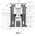
- the measurement cell 1 for the thermal conductivity of a gas according to the invention comprises an inlet orifice 2 and an outlet orifice 3 of the gas.
- a gas circulation channel 4 is arranged between said inlet orifice 2 and said outlet orifice 3 so as to form a gas flow path inside the measuring cell 1.
- the measuring cell 1 also comprises a housing 5 forming a measuring chamber 6 which contains a sensor 7 of thermal conductivity and thus protects the sensor 7 from the arrival of a flow of gas directly on said sensor.
- the measurement chamber 6 communicates directly with a portion 8 of said channel via a single gas inlet orifice 9 of said housing, said intake orifice being made through the thickness of the housing. 5.
- said inlet orifice 9 is located in a plane oriented with respect to the gas circulation path in said portion 8 of the gas circulation channel so that the gas enters mainly by diffusion by said intake port 9 inside the measuring chamber 6.
- the portion 8 extends in such a way that the gas circulates substantially parallel to said plane of the inlet orifice 9.
- the gas velocity is reduced to the maximum and tends to a zero value in the vicinity of the thermal conductivity sensor 7.
- the gas entering the housing 5 is renewed by diffusion and the variations in gas flow rate at the conductivity sensor 7 in the measurement chamber 6 are significantly limited.
- the measuring cell 1 according to the present invention thus makes it possible to advantageously limit the lack of stability of the measurements of the thermal conductivity of a gas related to variations in the flow rate of the gas.
- the structure of the measuring cell further has a symmetrical structure to ensure optimal compactness.
- the housing 5 is placed inside an envelope 10 of substantially cylindrical shape extending along a longitudinal axis A.
- the housing 5 comprises a support portion 11 for the thermal conductivity sensor 7 and a cover 12 covering said support portion.
- the casing 5 is of the right cylinder type and is advantageously positioned coaxially with the longitudinal axis A of the casing 10.
- the longitudinal axis of said housing 5 is identical to the longitudinal axis A of the envelope 10.
- the support portion 11 is disk-shaped and corresponds to one of the bases of the cylinder, the housing 12 including the other base of the cylinder.
- the cover 12 of said housing comprises the inlet port 9, the latter could be located anywhere on the hood provided that the gas diffusion conditions inside the housing 5 are respected.
- the inlet orifice 9 of the gas is located in the center of the base of said hood, the plane of the inlet orifice 9 being perpendicular to the longitudinal axis A.
- the inlet orifice 9 has a circular cross-section with a diameter of less than 3 mm, for example of the order of 1 mm, in order to optimize the diffusion phenomenon of the gas inside the measuring chamber.
- the gas circulation channel 4 comprises a first portion 81 communicating with the inlet orifice 2 and said portion 8 of said channel, and a second portion 82 communicating with said portion 8 and the outlet orifice 3.
- these first and second parts 81, 82 are parallel and symmetrical with respect to the longitudinal axis A of the envelope 10 and make it possible to obtain a measuring cell 1 having optimum compactness.
- the casing 10 has a closed end in which are machined said first and second parts 81, 82.
- first and second portions 81, 82 of the channel form an integral part of the envelope 10.
- the casing 10 further comprises an annular protrusion 18 allowing the support portion 11 of said housing to abut on said annular protuberance.
- the thermal conductivity sensor 7 comprising a chip 71 for measuring the thermal conductivity and a temperature sensor 72.
- the chip 71 and the probe 72 are attached adjacent to the support portion 11 so as to optimize the temperature control in the measurement chamber 6.
- the temperature probe 72 is integrated within the thermal conductivity sensor 7, as close as possible to the chip 71.
- the temperature regulation can be done precisely closer to the measuring point of the thermal conductivity.
- the sensor connections 73 pass through an opening made in the support portion 11, said connections being connected to a printed circuit 74.
- the printed circuit 74 is an interface between the thermal conductivity sensor 7 and a digital electronic data acquisition and processing card (not shown), said electronic acquisition card being electrically connected to the printed circuit 74.
- the temperature of the gas flowing in the channel 4 must preferably be substantially the same as the measured temperature inside the measuring chamber 6 by the temperature sensor 72.
- a heating means 13 is arranged around said envelope to limit any temperature gradient within the measuring cell 1, the heating means 13 being of the surface type.
- the temperature inside the measuring chamber 6 is regulated by the heating means 13 via the temperature sensor 72.
- the digital electronic data acquisition and processing card periodically integrates the temperature measurements made by the temperature sensor 72.
- PID Proportional Integral Derivative
- a power circuit (not shown) provides the heating means 13 the power necessary to maintain the temperature around a set point.
- the heating means 13 is for example a resistive wire wound around the casing 10 of the measuring cell.
- the thermal conductivity sensor 7, in particular the chip 71, is not disturbed by a sudden change in the temperature of the gas when it enters the measuring chamber 6.
- the casing 10 and the casing 5 are made of thermally conductive materials, in particular the casing 10 and the casing 5 are made of steel.
- the measuring cell 1 In order to use the measuring cell 1 according to the invention in a gas analyzer, the measuring cell, as such, must preferably be thermally insulated from disturbances related to the outside temperature.
- an insulating ring is placed around the casing 10.
- This insulating ring is for example glass wool about 20 mm thick.
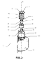
- the measuring cell 1 comprises an outer shell 14 of plastics material as represented in FIG.
- This outer shell 14 is preferably copolymer of acrylonitrile, butadiene and styrene (ABS).
- the glass wool is thus placed between the envelope 10 and the outer shell 14 to ensure better insulation.
- the outer shell 14 for example of cylindrical shape, has at one end an opening 141 for easy access to the inlet ports 2 and outlet 3 of the measuring cell.
- an insulating part 19, according to FIGS. 1 and 2 is positioned inside the envelope 10 between the support portion 11 and the printed circuit 74.
- Said insulating piece 19 is of cylindrical shape so as to be positioned coaxially with the longitudinal axis A.
- the material chosen for the insulating part 19 is PEEK (Poly-Ether-Ether-Ketone)
- PEEK is a polymer material of low thermal conductivity, chemically inert and resistant to high temperatures.
- Said insulating piece 19 is fixed by fastening means 20 to the casing 10 by crushing an o-ring seal 21 positioned between the support portion 11 for the thermal conductivity sensor 7 and the insulating part 19, thus guaranteeing a seal pneumatic.
- the printed circuit 74 is, for its part, also fixed by other fixing means 22 on the insulating part 19, these fixing means 22 being visible only in FIG.
- an insulating cap 23 for example made of polyimide foam, is placed inside the outer shell 14 between the printed circuit 74 and said outer shell 14.
- said plug 23 is of cylindrical shape and can be positioned coaxially with the longitudinal axis A.
- the measurement cell 1 thus constituted significantly eliminates external temperature variations and makes it possible to optimize the accuracy and the stability of the measurements by the thermal conductivity sensor 7.
- the temperature inside the measuring chamber is precisely regulated to plus or minus 0.01 ° C.
- the measuring cell according to the present invention can be used within a gas analyzer.
- At least two measuring cells as previously described may be used.
- FIGS. 300 and 400 A measurement system 200 with two measurement cells according to the invention is shown in FIGS. 300 and 400 in its use within a gas analyzer 300.
- This measurement system 200 comprises a first and a second measuring cell 101, 102 and a thermal decoupling member 150.
- the first and the second measurement cells 101, 102 are put in series by means of the thermal decoupling member 150 or in other words a support " manifold ", preferably PEEK, which ensures a thermal decoupling between each measuring cell 101, 102.
- the thermal decoupling member 150 makes it possible to limit as far as possible all the heat transfers from one measurement cell to the other.
- the thermal decoupling member 150 comprises a gas circulation duct 151 putting the outlet orifice 3 of the gas of the first measurement cell 101 into communication with the inlet orifice 2 of the gas of the second measuring cell 102. through said thermal decoupling member.
- the circulation duct 151 is advantageously directly machined inside the thermal decoupling member 150.
- the gas flowing from the first measuring cell 101 to the second measuring cell 102 it is preferable to place in series the first measuring cell 101 followed by the second measuring cell 102 when the temperature of the first measuring cell 101, for example 67 ° C, is lower than the temperature of the second measuring cell 102, for example 113 ° C.
- the measuring system 200 for measuring at two different temperatures can be generalized by placing as many series measuring cells interconnected by means of the thermal decoupling member and providing as many ducts as necessary.
- the measurement system 200 can be integrated in any equipment, for example in a gas analyzer 300.
- the two measuring cells 101, 102 communicate with a one-piece part 301 of the gas analyzer via the thermal decoupling member 150.
- the thermal decoupling member 150 thus makes it possible to limit as far as possible all the heat transfers between the measuring cells 101, 102 and the monoblock part 301.
- the one-piece portion 301 of parallelepipedal shape has a face grouping an inlet port 302 and an outlet port 303 of the gas of the analyzer 300.
- the inlet 302 of said analyzer is in communication with the inlet port 2 of the first measurement cell 101 and the outlet port 303 of said analyzer is in communication with the outlet port 3 of the second cell. 202, in order to allow the gas to circulate inside the gas analyzer.
- the gas first enters the analyzer inlet 302 and circulates within the integral portion 301, preferably stainless steel, in which first and second paths are machined. 304, 305 gas circulation.
- a first solenoid valve 306 acting on the first gas flow path 304 near the inlet port 302 of the analyzer makes it possible to control the flow of the gas inside the analyzer 300.
- the first gas flow path 304 brings the gas to the inlet port 2 of the first measuring cell 101 through the thermal decoupling member 150.
- the gas thus circulates inside the first measuring cell 101 to its outlet orifice 3.
- the gas flows inside the second measuring cell 102 to the outlet orifice 3 of said second measuring cell .
- the gas passes through the thermal decoupling member 150 to flow in the second path 305 of the gas flow and arrives at the outlet port 303 of the gas analyzer.
- a second solenoid valve 307 placed near the outlet port 303 of the analyzer, also controls the flow of gas inside said analyzer.
- the gas analyzer 300 as diagrammatically shown in FIG. 3 further comprises a gas pressure sensor 320 for measuring the pressure of the gas flowing inside said analyzer.
- This pressure sensor 320 makes it possible to dispense with the disturbances related to gas pressure variations at a lower cost and is positioned to measure the pressure before the gas enters the first measuring cell 101.
- said pressure sensor is positioned at the first gas flow path 304 inside the one-piece portion 301 of the analyzer.
- the measurement of the pressure thus makes it possible, via a calculation algorithm, to correct the signal supplied by the thermal conductivity sensor 7 of each measuring cell 101, 102.
- the gas analyzer 300 may include other types of sensors to measure other physical properties of the gas for the determination of energy properties through the correlative methods.
- the gas analyzer 300 may also comprise a diaphragm-type pressure-reducing member 321 positioned in the circulation path of the gas between the measuring chamber of the second measuring cell 102 and the outlet port 303 of the gas analyzer.
- the diaphragm is positioned inside the thermal decoupling member 150 near the outlet orifice 3 of the second measuring cell 102.
- the pressure-reducing member 321 thus makes it possible to improve the preheating of the gas inside the gas circulation channel 4.
- the flow rate of the gas is thus slowed down in said channel, which makes it possible to reach the desired measurement temperature more rapidly according to the optimization of the various parameters such as the heating power, the temperature at the inlet of the channel, the temperature at the outlet of the channel, the preheating temperature of the gas, the heating temperature of the gas flowing in the housing.
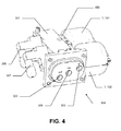
- FIG. 4 shows the gas analyzer 300 in perspective comprising the one-piece part 301, the two solenoid valves 306, 307, and the measurement system with the first and second measuring cells 101, 102 together with the thermal decoupling member 150 .
- the one-piece portion 301 and the measuring system are perfectly matched to form a compact analyzer.
- the gas analyzer according to the present invention has a limited size for an easy industrial installation and allows quick assembly.
- the inlet ports 302, 308 and 303 of the gas analyzer are grouped on one and the same face of the one-piece portion of said analyzer as shown in FIG. 4, and thus allow easy access to the user.
- the gain in stability and accuracy in the measurement of thermal conductivity significantly improves the metrological performance of gas analyzers using this measurement.
- the means used to overcome such disturbances can be used alone or in combination at the level of the measuring cell, the measuring system comprising at least two of said cells and / or the gas analyzer comprising at least one cell.
- the present invention is not limited to the implementation example which has just been described and relates in general to all measuring cells, measuring systems and gas analyzers that can be envisaged on the basis of the general indications provided in FIG. presentation of the invention.
Landscapes
- Physics & Mathematics (AREA)
- Health & Medical Sciences (AREA)
- Life Sciences & Earth Sciences (AREA)
- Chemical & Material Sciences (AREA)
- Analytical Chemistry (AREA)
- Biochemistry (AREA)
- General Health & Medical Sciences (AREA)
- General Physics & Mathematics (AREA)
- Immunology (AREA)
- Pathology (AREA)
- Investigating Or Analyzing Materials Using Thermal Means (AREA)
- Investigating Or Analyzing Materials By The Use Of Electric Means (AREA)
Applications Claiming Priority (1)
| Application Number | Priority Date | Filing Date | Title |
|---|---|---|---|
| FR0654803A FR2908515B1 (fr) | 2006-11-09 | 2006-11-09 | Cellule de mesure de la conductivite thermique d'un gaz |
Publications (2)
| Publication Number | Publication Date |
|---|---|
| EP1921443A1 true EP1921443A1 (de) | 2008-05-14 |
| EP1921443B1 EP1921443B1 (de) | 2009-10-14 |
Family
ID=38162163
Family Applications (1)
| Application Number | Title | Priority Date | Filing Date |
|---|---|---|---|
| EP07119724A Not-in-force EP1921443B1 (de) | 2006-11-09 | 2007-10-31 | Zelle zur Messung der thermischen Leitfähigkeit eines Gases |
Country Status (4)
| Country | Link |
|---|---|
| EP (1) | EP1921443B1 (de) |
| AT (1) | ATE445834T1 (de) |
| DE (1) | DE602007002766D1 (de) |
| FR (1) | FR2908515B1 (de) |
Cited By (3)
| Publication number | Priority date | Publication date | Assignee | Title |
|---|---|---|---|---|
| EP2899540A1 (de) * | 2014-01-27 | 2015-07-29 | Siemens Aktiengesellschaft | Wärmeleitfähigkeits-Analysator |
| CN110214270A (zh) * | 2016-12-13 | 2019-09-06 | 丰田自动车株式会社 | 热特性评价测定装置及使用该测定装置的热特性的评价测定方法 |
| US12337276B2 (en) * | 2019-02-01 | 2025-06-24 | Evonik Operations Gmbh | Device and a membrane process for separating gas components from a gas stream having varying composition or flow rate |
Citations (5)
| Publication number | Priority date | Publication date | Assignee | Title |
|---|---|---|---|---|
| US4885938A (en) * | 1988-12-16 | 1989-12-12 | Honeywell Inc. | Flowmeter fluid composition correction |
| WO1993008457A1 (en) * | 1991-10-23 | 1993-04-29 | Niagara Mohawk Power Corporation | On-line combustionless measurement of gaseous fuels fed to gas consumption devices |
| WO2000045163A2 (en) * | 1999-01-28 | 2000-08-03 | Honeywell Inc. | Microsensor housing |
| DE10146212A1 (de) * | 2001-09-19 | 2003-04-10 | Stange Elektronik Gmbh | Verfahren und Vorrichtung zur Bestimmung des Wasserstoffgehalts von Gasgemischen |
| US20050265422A1 (en) * | 2004-05-28 | 2005-12-01 | Honeywell International Inc. | Differetial thermal sensors |
-
2006
- 2006-11-09 FR FR0654803A patent/FR2908515B1/fr not_active Expired - Fee Related
-
2007
- 2007-10-31 DE DE602007002766T patent/DE602007002766D1/de active Active
- 2007-10-31 AT AT07119724T patent/ATE445834T1/de not_active IP Right Cessation
- 2007-10-31 EP EP07119724A patent/EP1921443B1/de not_active Not-in-force
Patent Citations (5)
| Publication number | Priority date | Publication date | Assignee | Title |
|---|---|---|---|---|
| US4885938A (en) * | 1988-12-16 | 1989-12-12 | Honeywell Inc. | Flowmeter fluid composition correction |
| WO1993008457A1 (en) * | 1991-10-23 | 1993-04-29 | Niagara Mohawk Power Corporation | On-line combustionless measurement of gaseous fuels fed to gas consumption devices |
| WO2000045163A2 (en) * | 1999-01-28 | 2000-08-03 | Honeywell Inc. | Microsensor housing |
| DE10146212A1 (de) * | 2001-09-19 | 2003-04-10 | Stange Elektronik Gmbh | Verfahren und Vorrichtung zur Bestimmung des Wasserstoffgehalts von Gasgemischen |
| US20050265422A1 (en) * | 2004-05-28 | 2005-12-01 | Honeywell International Inc. | Differetial thermal sensors |
Cited By (4)
| Publication number | Priority date | Publication date | Assignee | Title |
|---|---|---|---|---|
| EP2899540A1 (de) * | 2014-01-27 | 2015-07-29 | Siemens Aktiengesellschaft | Wärmeleitfähigkeits-Analysator |
| US9546972B2 (en) | 2014-01-27 | 2017-01-17 | Siemens Aktiengesellschaft | Thermal conductivity detector |
| CN110214270A (zh) * | 2016-12-13 | 2019-09-06 | 丰田自动车株式会社 | 热特性评价测定装置及使用该测定装置的热特性的评价测定方法 |
| US12337276B2 (en) * | 2019-02-01 | 2025-06-24 | Evonik Operations Gmbh | Device and a membrane process for separating gas components from a gas stream having varying composition or flow rate |
Also Published As
| Publication number | Publication date |
|---|---|
| FR2908515B1 (fr) | 2008-12-26 |
| EP1921443B1 (de) | 2009-10-14 |
| FR2908515A1 (fr) | 2008-05-16 |
| DE602007002766D1 (de) | 2009-11-26 |
| ATE445834T1 (de) | 2009-10-15 |
Similar Documents
| Publication | Publication Date | Title |
|---|---|---|
| EP1060348B1 (de) | Vorrichtung zur regelung des luft/gasverhältnisses eines brenners mit einer druckunterschiedmessvorrichtung | |
| EP0664449B1 (de) | Verfahren und Vorrichtung zur Lieferung von Gas an eine Vorrichtung zur Analyse von Verunreinigungsspuren in einem Gas | |
| EP1921443B1 (de) | Zelle zur Messung der thermischen Leitfähigkeit eines Gases | |
| EP0927875A1 (de) | Sensor für thermischen Massendurchflussmesser und Verfahren zu seiner Herstellung | |
| FR2829237A1 (fr) | Appareil et procedes de mesure de pression par perte de chaleur | |
| FR2820202A1 (fr) | Capteur de pression et moteur de fusee l'incorporant | |
| FR2576688A1 (fr) | Dispositif de mesure de la conductivite thermique de gaz | |
| EP0326494A1 (de) | Vorrichtung für die Messung der Wärmekapazität einer Brennstoffströmung | |
| WO2010086557A1 (fr) | Appareil éthylomètre portable | |
| EP0597530A1 (de) | Volumendurchflussmesser zum Messen der Flugzeit | |
| FR3040489A1 (fr) | Capteur de flux thermique mettant en œuvre au moins un resonateur optique, capteur de gaz et jauge pirani comportant au moins un tel capteur. | |
| FR2849200A1 (fr) | Detecteur de gaz a structure perfectionnee pour limiter les dommages thermiques | |
| FR3005729A3 (fr) | Appareil de mesure de courant pour mesurer le courant d'un milieu | |
| FR2855260A1 (fr) | Element de mesure pour un capteur de passage notamment un debitmetre massique d'air equipant un moteur a combustion interne | |
| EP0076759B1 (de) | Vorrichtung zur kontinuierlichen Bestimmung des Heizwertes von Gasen | |
| EP1016853B1 (de) | Fiberoptischer polarimetrischer Sensor | |
| EP0170552B1 (de) | Druckverlustdurchflussmesser und Regelvorrichtung mit einem derartigen Durchflussmesser | |
| FR2748811A1 (fr) | Mesure de flux surfacique de gaz | |
| EP1583960A1 (de) | Einrichtung zurautomatisierten kopplung zwischen einem mikrochromatograph und einemmassenspektrometer mit temperatureinstellung | |
| FR2496885A1 (fr) | Appareil de mesure de pression | |
| FR2855261A1 (fr) | Capteur de passage a deux resistances | |
| FR3074363A1 (fr) | Pile a combustible comprenant un dispositif de regulation de pression et procede de regulation de pression | |
| EP0305435B1 (de) | Tragbare, selbständige vorrichtung zum nachweisen eines gaszusammensetzung mit verwendung der flammen-spektralphotometrie | |
| WO2024100364A1 (fr) | Appareil pour mesurer un taux d'humidité dans l'air | |
| EP4607165A1 (de) | System zur nichtinvasiven bestimmung einer temperatur eines leiters eines elektrischen kabels |
Legal Events
| Date | Code | Title | Description |
|---|---|---|---|
| PUAI | Public reference made under article 153(3) epc to a published international application that has entered the european phase |
Free format text: ORIGINAL CODE: 0009012 |
|
| AK | Designated contracting states |
Kind code of ref document: A1 Designated state(s): AT BE BG CH CY CZ DE DK EE ES FI FR GB GR HU IE IS IT LI LT LU LV MC MT NL PL PT RO SE SI SK TR |
|
| AX | Request for extension of the european patent |
Extension state: AL BA HR MK RS |
|
| 17P | Request for examination filed |
Effective date: 20081114 |
|
| AKX | Designation fees paid |
Designated state(s): AT BE BG CH CY CZ DE DK EE ES FI FR GB GR HU IE IS IT LI LT LU LV MC MT NL PL PT RO SE SI SK TR |
|
| 17Q | First examination report despatched |
Effective date: 20090113 |
|
| GRAP | Despatch of communication of intention to grant a patent |
Free format text: ORIGINAL CODE: EPIDOSNIGR1 |
|
| GRAS | Grant fee paid |
Free format text: ORIGINAL CODE: EPIDOSNIGR3 |
|
| GRAA | (expected) grant |
Free format text: ORIGINAL CODE: 0009210 |
|
| RIN1 | Information on inventor provided before grant (corrected) |
Inventor name: CHARRIER, STEPHANE Inventor name: NEXON, PIERRE Inventor name: GIRAUDET, FREDERIC |
|
| AK | Designated contracting states |
Kind code of ref document: B1 Designated state(s): AT BE BG CH CY CZ DE DK EE ES FI FR GB GR HU IE IS IT LI LT LU LV MC MT NL PL PT RO SE SI SK TR |
|
| REG | Reference to a national code |
Ref country code: GB Ref legal event code: FG4D Free format text: NOT ENGLISH |
|
| REG | Reference to a national code |
Ref country code: CH Ref legal event code: EP |
|
| REG | Reference to a national code |
Ref country code: IE Ref legal event code: FG4D |
|
| REF | Corresponds to: |
Ref document number: 602007002766 Country of ref document: DE Date of ref document: 20091126 Kind code of ref document: P |
|
| LTIE | Lt: invalidation of european patent or patent extension |
Effective date: 20091014 |
|
| NLV1 | Nl: lapsed or annulled due to failure to fulfill the requirements of art. 29p and 29m of the patents act | ||
| BERE | Be: lapsed |
Owner name: DALKIA FRANCE Effective date: 20091031 Owner name: ACTARIS SAS Effective date: 20091031 |
|
| PG25 | Lapsed in a contracting state [announced via postgrant information from national office to epo] |
Ref country code: SE Free format text: LAPSE BECAUSE OF FAILURE TO SUBMIT A TRANSLATION OF THE DESCRIPTION OR TO PAY THE FEE WITHIN THE PRESCRIBED TIME-LIMIT Effective date: 20091014 Ref country code: PT Free format text: LAPSE BECAUSE OF FAILURE TO SUBMIT A TRANSLATION OF THE DESCRIPTION OR TO PAY THE FEE WITHIN THE PRESCRIBED TIME-LIMIT Effective date: 20100215 Ref country code: ES Free format text: LAPSE BECAUSE OF FAILURE TO SUBMIT A TRANSLATION OF THE DESCRIPTION OR TO PAY THE FEE WITHIN THE PRESCRIBED TIME-LIMIT Effective date: 20100125 Ref country code: IS Free format text: LAPSE BECAUSE OF FAILURE TO SUBMIT A TRANSLATION OF THE DESCRIPTION OR TO PAY THE FEE WITHIN THE PRESCRIBED TIME-LIMIT Effective date: 20100214 Ref country code: LT Free format text: LAPSE BECAUSE OF FAILURE TO SUBMIT A TRANSLATION OF THE DESCRIPTION OR TO PAY THE FEE WITHIN THE PRESCRIBED TIME-LIMIT Effective date: 20091014 Ref country code: FI Free format text: LAPSE BECAUSE OF FAILURE TO SUBMIT A TRANSLATION OF THE DESCRIPTION OR TO PAY THE FEE WITHIN THE PRESCRIBED TIME-LIMIT Effective date: 20091014 |
|
| REG | Reference to a national code |
Ref country code: IE Ref legal event code: FD4D |
|
| PG25 | Lapsed in a contracting state [announced via postgrant information from national office to epo] |
Ref country code: SI Free format text: LAPSE BECAUSE OF FAILURE TO SUBMIT A TRANSLATION OF THE DESCRIPTION OR TO PAY THE FEE WITHIN THE PRESCRIBED TIME-LIMIT Effective date: 20091014 Ref country code: LV Free format text: LAPSE BECAUSE OF FAILURE TO SUBMIT A TRANSLATION OF THE DESCRIPTION OR TO PAY THE FEE WITHIN THE PRESCRIBED TIME-LIMIT Effective date: 20091014 Ref country code: PL Free format text: LAPSE BECAUSE OF FAILURE TO SUBMIT A TRANSLATION OF THE DESCRIPTION OR TO PAY THE FEE WITHIN THE PRESCRIBED TIME-LIMIT Effective date: 20091014 Ref country code: MC Free format text: LAPSE BECAUSE OF NON-PAYMENT OF DUE FEES Effective date: 20091031 |
|
| PG25 | Lapsed in a contracting state [announced via postgrant information from national office to epo] |
Ref country code: AT Free format text: LAPSE BECAUSE OF FAILURE TO SUBMIT A TRANSLATION OF THE DESCRIPTION OR TO PAY THE FEE WITHIN THE PRESCRIBED TIME-LIMIT Effective date: 20091014 |
|
| PG25 | Lapsed in a contracting state [announced via postgrant information from national office to epo] |
Ref country code: RO Free format text: LAPSE BECAUSE OF FAILURE TO SUBMIT A TRANSLATION OF THE DESCRIPTION OR TO PAY THE FEE WITHIN THE PRESCRIBED TIME-LIMIT Effective date: 20091014 Ref country code: BG Free format text: LAPSE BECAUSE OF FAILURE TO SUBMIT A TRANSLATION OF THE DESCRIPTION OR TO PAY THE FEE WITHIN THE PRESCRIBED TIME-LIMIT Effective date: 20100114 Ref country code: IE Free format text: LAPSE BECAUSE OF FAILURE TO SUBMIT A TRANSLATION OF THE DESCRIPTION OR TO PAY THE FEE WITHIN THE PRESCRIBED TIME-LIMIT Effective date: 20091014 Ref country code: DK Free format text: LAPSE BECAUSE OF FAILURE TO SUBMIT A TRANSLATION OF THE DESCRIPTION OR TO PAY THE FEE WITHIN THE PRESCRIBED TIME-LIMIT Effective date: 20091014 Ref country code: EE Free format text: LAPSE BECAUSE OF FAILURE TO SUBMIT A TRANSLATION OF THE DESCRIPTION OR TO PAY THE FEE WITHIN THE PRESCRIBED TIME-LIMIT Effective date: 20091014 |
|
| PLBE | No opposition filed within time limit |
Free format text: ORIGINAL CODE: 0009261 |
|
| STAA | Information on the status of an ep patent application or granted ep patent |
Free format text: STATUS: NO OPPOSITION FILED WITHIN TIME LIMIT |
|
| PG25 | Lapsed in a contracting state [announced via postgrant information from national office to epo] |
Ref country code: SK Free format text: LAPSE BECAUSE OF FAILURE TO SUBMIT A TRANSLATION OF THE DESCRIPTION OR TO PAY THE FEE WITHIN THE PRESCRIBED TIME-LIMIT Effective date: 20091014 Ref country code: CZ Free format text: LAPSE BECAUSE OF FAILURE TO SUBMIT A TRANSLATION OF THE DESCRIPTION OR TO PAY THE FEE WITHIN THE PRESCRIBED TIME-LIMIT Effective date: 20091014 |
|
| 26N | No opposition filed |
Effective date: 20100715 |
|
| PG25 | Lapsed in a contracting state [announced via postgrant information from national office to epo] |
Ref country code: GR Free format text: LAPSE BECAUSE OF FAILURE TO SUBMIT A TRANSLATION OF THE DESCRIPTION OR TO PAY THE FEE WITHIN THE PRESCRIBED TIME-LIMIT Effective date: 20100115 Ref country code: BE Free format text: LAPSE BECAUSE OF NON-PAYMENT OF DUE FEES Effective date: 20091031 |
|
| PG25 | Lapsed in a contracting state [announced via postgrant information from national office to epo] |
Ref country code: IT Free format text: LAPSE BECAUSE OF FAILURE TO SUBMIT A TRANSLATION OF THE DESCRIPTION OR TO PAY THE FEE WITHIN THE PRESCRIBED TIME-LIMIT Effective date: 20091014 |
|
| PG25 | Lapsed in a contracting state [announced via postgrant information from national office to epo] |
Ref country code: MT Free format text: LAPSE BECAUSE OF FAILURE TO SUBMIT A TRANSLATION OF THE DESCRIPTION OR TO PAY THE FEE WITHIN THE PRESCRIBED TIME-LIMIT Effective date: 20091014 Ref country code: LU Free format text: LAPSE BECAUSE OF NON-PAYMENT OF DUE FEES Effective date: 20091031 |
|
| PG25 | Lapsed in a contracting state [announced via postgrant information from national office to epo] |
Ref country code: HU Free format text: LAPSE BECAUSE OF FAILURE TO SUBMIT A TRANSLATION OF THE DESCRIPTION OR TO PAY THE FEE WITHIN THE PRESCRIBED TIME-LIMIT Effective date: 20100415 |
|
| PG25 | Lapsed in a contracting state [announced via postgrant information from national office to epo] |
Ref country code: TR Free format text: LAPSE BECAUSE OF FAILURE TO SUBMIT A TRANSLATION OF THE DESCRIPTION OR TO PAY THE FEE WITHIN THE PRESCRIBED TIME-LIMIT Effective date: 20091014 |
|
| PG25 | Lapsed in a contracting state [announced via postgrant information from national office to epo] |
Ref country code: CY Free format text: LAPSE BECAUSE OF FAILURE TO SUBMIT A TRANSLATION OF THE DESCRIPTION OR TO PAY THE FEE WITHIN THE PRESCRIBED TIME-LIMIT Effective date: 20091014 |
|
| REG | Reference to a national code |
Ref country code: CH Ref legal event code: PL |
|
| PG25 | Lapsed in a contracting state [announced via postgrant information from national office to epo] |
Ref country code: CH Free format text: LAPSE BECAUSE OF NON-PAYMENT OF DUE FEES Effective date: 20111031 Ref country code: LI Free format text: LAPSE BECAUSE OF NON-PAYMENT OF DUE FEES Effective date: 20111031 |
|
| PG25 | Lapsed in a contracting state [announced via postgrant information from national office to epo] |
Ref country code: NL Free format text: LAPSE BECAUSE OF FAILURE TO SUBMIT A TRANSLATION OF THE DESCRIPTION OR TO PAY THE FEE WITHIN THE PRESCRIBED TIME-LIMIT Effective date: 20091014 |
|
| REG | Reference to a national code |
Ref country code: FR Ref legal event code: CD Owner name: DALKIA FRANCE, FR Effective date: 20140423 Ref country code: FR Ref legal event code: CD Owner name: ITRON FRANCE, FR Effective date: 20140423 Ref country code: FR Ref legal event code: CA Effective date: 20140423 |
|
| REG | Reference to a national code |
Ref country code: DE Ref legal event code: R081 Ref document number: 602007002766 Country of ref document: DE Owner name: ITRON FRANCE, FR Free format text: FORMER OWNER: ACTARIS S.A.S, DALKIA FRANCE, , FR Effective date: 20140515 Ref country code: DE Ref legal event code: R081 Ref document number: 602007002766 Country of ref document: DE Owner name: ITRON GLOBAL SARL, LIBERTY LAKE, US Free format text: FORMER OWNERS: ACTARIS S.A.S, BOULOGNE BILLANCOURT, FR; DALKIA FRANCE, SAINT-ANDRE, FR Effective date: 20140515 Ref country code: DE Ref legal event code: R081 Ref document number: 602007002766 Country of ref document: DE Owner name: ITRON FRANCE, FR Free format text: FORMER OWNERS: ACTARIS S.A.S, BOULOGNE BILLANCOURT, FR; DALKIA FRANCE, SAINT-ANDRE, FR Effective date: 20140515 |
|
| REG | Reference to a national code |
Ref country code: FR Ref legal event code: PLFP Year of fee payment: 10 |
|
| REG | Reference to a national code |
Ref country code: DE Ref legal event code: R081 Ref document number: 602007002766 Country of ref document: DE Owner name: ITRON GLOBAL SARL, LIBERTY LAKE, US Free format text: FORMER OWNER: ITRON FRANCE, ISSY-LES-MOULINEAUX, FR |
|
| REG | Reference to a national code |
Ref country code: FR Ref legal event code: PLFP Year of fee payment: 11 |
|
| PGFP | Annual fee paid to national office [announced via postgrant information from national office to epo] |
Ref country code: FR Payment date: 20170918 Year of fee payment: 11 |
|
| PGFP | Annual fee paid to national office [announced via postgrant information from national office to epo] |
Ref country code: DE Payment date: 20171025 Year of fee payment: 11 |
|
| PGFP | Annual fee paid to national office [announced via postgrant information from national office to epo] |
Ref country code: GB Payment date: 20171025 Year of fee payment: 11 |
|
| REG | Reference to a national code |
Ref country code: DE Ref legal event code: R119 Ref document number: 602007002766 Country of ref document: DE |
|
| GBPC | Gb: european patent ceased through non-payment of renewal fee |
Effective date: 20181031 |
|
| PG25 | Lapsed in a contracting state [announced via postgrant information from national office to epo] |
Ref country code: DE Free format text: LAPSE BECAUSE OF NON-PAYMENT OF DUE FEES Effective date: 20190501 |
|
| PG25 | Lapsed in a contracting state [announced via postgrant information from national office to epo] |
Ref country code: FR Free format text: LAPSE BECAUSE OF NON-PAYMENT OF DUE FEES Effective date: 20181031 |
|
| PG25 | Lapsed in a contracting state [announced via postgrant information from national office to epo] |
Ref country code: GB Free format text: LAPSE BECAUSE OF NON-PAYMENT OF DUE FEES Effective date: 20181031 |