EP1921461A1 - Bobine de type cage d'oiseau à double accord pour l'IRM - Google Patents
Bobine de type cage d'oiseau à double accord pour l'IRM Download PDFInfo
- Publication number
- EP1921461A1 EP1921461A1 EP07021565A EP07021565A EP1921461A1 EP 1921461 A1 EP1921461 A1 EP 1921461A1 EP 07021565 A EP07021565 A EP 07021565A EP 07021565 A EP07021565 A EP 07021565A EP 1921461 A1 EP1921461 A1 EP 1921461A1
- Authority
- EP
- European Patent Office
- Prior art keywords
- coil
- conducting
- coils
- condenser
- loop
- Prior art date
- Legal status (The legal status is an assumption and is not a legal conclusion. Google has not performed a legal analysis and makes no representation as to the accuracy of the status listed.)
- Ceased
Links
- 230000003068 static effect Effects 0.000 claims description 29
- 229910052739 hydrogen Inorganic materials 0.000 claims description 25
- 239000001257 hydrogen Substances 0.000 claims description 25
- UFHFLCQGNIYNRP-UHFFFAOYSA-N Hydrogen Chemical compound [H][H] UFHFLCQGNIYNRP-UHFFFAOYSA-N 0.000 claims description 24
- 230000005540 biological transmission Effects 0.000 claims description 21
- 239000004020 conductor Substances 0.000 claims description 21
- 238000003384 imaging method Methods 0.000 claims description 10
- 238000005481 NMR spectroscopy Methods 0.000 claims description 6
- 230000005611 electricity Effects 0.000 claims description 4
- 238000013421 nuclear magnetic resonance imaging Methods 0.000 claims description 2
- 230000035945 sensitivity Effects 0.000 abstract description 35
- 238000002595 magnetic resonance imaging Methods 0.000 description 66
- 238000000034 method Methods 0.000 description 14
- 230000009977 dual effect Effects 0.000 description 13
- OAICVXFJPJFONN-UHFFFAOYSA-N Phosphorus Chemical compound [P] OAICVXFJPJFONN-UHFFFAOYSA-N 0.000 description 10
- OKTJSMMVPCPJKN-UHFFFAOYSA-N Carbon Chemical compound [C] OKTJSMMVPCPJKN-UHFFFAOYSA-N 0.000 description 8
- 229910052799 carbon Inorganic materials 0.000 description 8
- 238000012545 processing Methods 0.000 description 7
- DGAQECJNVWCQMB-PUAWFVPOSA-M Ilexoside XXIX Chemical compound C[C@@H]1CC[C@@]2(CC[C@@]3(C(=CC[C@H]4[C@]3(CC[C@@H]5[C@@]4(CC[C@@H](C5(C)C)OS(=O)(=O)[O-])C)C)[C@@H]2[C@]1(C)O)C)C(=O)O[C@H]6[C@@H]([C@H]([C@@H]([C@H](O6)CO)O)O)O.[Na+] DGAQECJNVWCQMB-PUAWFVPOSA-M 0.000 description 5
- 150000002431 hydrogen Chemical class 0.000 description 5
- 238000004088 simulation Methods 0.000 description 5
- 229910052708 sodium Inorganic materials 0.000 description 5
- 239000011734 sodium Substances 0.000 description 5
- 230000005672 electromagnetic field Effects 0.000 description 4
- 230000000877 morphologic effect Effects 0.000 description 3
- 238000012360 testing method Methods 0.000 description 3
- RYGMFSIKBFXOCR-UHFFFAOYSA-N Copper Chemical compound [Cu] RYGMFSIKBFXOCR-UHFFFAOYSA-N 0.000 description 2
- 230000004323 axial length Effects 0.000 description 2
- 229910052802 copper Inorganic materials 0.000 description 2
- 239000010949 copper Substances 0.000 description 2
- 238000013461 design Methods 0.000 description 2
- 230000009545 invasion Effects 0.000 description 2
- 239000000696 magnetic material Substances 0.000 description 2
- 230000002503 metabolic effect Effects 0.000 description 2
- 229910052751 metal Inorganic materials 0.000 description 2
- 239000002184 metal Substances 0.000 description 2
- 238000012986 modification Methods 0.000 description 2
- 230000004048 modification Effects 0.000 description 2
- 239000004925 Acrylic resin Substances 0.000 description 1
- 229920000178 Acrylic resin Polymers 0.000 description 1
- 229920004943 Delrin® Polymers 0.000 description 1
- PXGOKWXKJXAPGV-UHFFFAOYSA-N Fluorine Chemical compound FF PXGOKWXKJXAPGV-UHFFFAOYSA-N 0.000 description 1
- 239000003990 capacitor Substances 0.000 description 1
- 238000010586 diagram Methods 0.000 description 1
- 230000000694 effects Effects 0.000 description 1
- 229920006351 engineering plastic Polymers 0.000 description 1
- 229910052731 fluorine Inorganic materials 0.000 description 1
- 239000011737 fluorine Substances 0.000 description 1
- 230000010365 information processing Effects 0.000 description 1
- 238000009434 installation Methods 0.000 description 1
- 230000001678 irradiating effect Effects 0.000 description 1
- 238000004519 manufacturing process Methods 0.000 description 1
- 230000004060 metabolic process Effects 0.000 description 1
- 210000003205 muscle Anatomy 0.000 description 1
- 102000004169 proteins and genes Human genes 0.000 description 1
- 108090000623 proteins and genes Proteins 0.000 description 1
- 238000012956 testing procedure Methods 0.000 description 1
- XLYOFNOQVPJJNP-UHFFFAOYSA-N water Substances O XLYOFNOQVPJJNP-UHFFFAOYSA-N 0.000 description 1
Images


Classifications
-
- G—PHYSICS
- G01—MEASURING; TESTING
- G01R—MEASURING ELECTRIC VARIABLES; MEASURING MAGNETIC VARIABLES
- G01R33/00—Arrangements or instruments for measuring magnetic variables
- G01R33/20—Arrangements or instruments for measuring magnetic variables involving magnetic resonance
- G01R33/28—Details of apparatus provided for in groups G01R33/44 - G01R33/64
- G01R33/32—Excitation or detection systems, e.g. using radio frequency signals
- G01R33/34—Constructional details, e.g. resonators, specially adapted to MR
- G01R33/34046—Volume type coils, e.g. bird-cage coils; Quadrature bird-cage coils; Circularly polarised coils
-
- G—PHYSICS
- G01—MEASURING; TESTING
- G01R—MEASURING ELECTRIC VARIABLES; MEASURING MAGNETIC VARIABLES
- G01R33/00—Arrangements or instruments for measuring magnetic variables
- G01R33/20—Arrangements or instruments for measuring magnetic variables involving magnetic resonance
- G01R33/28—Details of apparatus provided for in groups G01R33/44 - G01R33/64
- G01R33/32—Excitation or detection systems, e.g. using radio frequency signals
- G01R33/36—Electrical details, e.g. matching or coupling of the coil to the receiver
- G01R33/3628—Tuning/matching of the transmit/receive coil
- G01R33/3635—Multi-frequency operation
Definitions
- the present invention relates to a coil device to be used for the transmission and reception of electromagnetic waves and a nuclear magnetic resonance imaging apparatus (hereinafter called MRI apparatus) using the same.
- MRI apparatus nuclear magnetic resonance imaging apparatus
- imaging of a subject to be examined is performed by placing the subject in a uniform static magnetic field generated by magnets, irradiating electromagnetic fields to excite nuclear spins inside the subject body, and then by receiving nuclear magnetic resonance signals that are the electromagnetic field generated by the nuclear spins.
- the irradiation of electromagnetic waves and the reception of nuclear magnetic resonance signals are conducted by the RF coil which transmits or receives electromagnetic waves of radio frequency (RF).
- RF radio frequency
- the transmitting coils, the receiving coils or the transmitting-receiving coils in various shapes suitably used for the MRI apparatus have been developed.
- the signals to be measured usually by the MRI apparatus are the signals from the hydrogen nucleus contained in water and fat.
- the sensitivity of the MRI apparatus has been improved by the employment of the higher magnetic field in the MRI apparatus in recent years.
- signals from the nucleus of other than hydrogen including those of phosphor, carbon, fluorine and sodium. It is expected that the imaging of signals from phosphor and carbon may enable the acquisition of information associated with the metabolism of muscles and proteins.
- MRI signals from non-hydrogen nuclides are significantly weaker or 10 to 100 times weaker, than those from hydrogen nucleus, so that it is difficult to obtain detailed images. Therefore, the MRI signals with low image resolution from non-hydrogen nuclide are usually displayed by superimposing them onto the morphological image produced from the MRI signals from hydrogen. In such case, it is desirable to image the MRI signals from hydrogen and of non-hydrogen nuclides at the same time or in succession.
- the coil used for the transmission and reception of MRI signals has high frequency selectivity
- the coil for obtaining MRI signals from hydrogen and the coil for obtaining signals from non-hydrogen nuclide were usually installed separately. But an attempt has been made recently to use a single coil to be tuned with two frequencies.
- the patent reference 1 discloses how to be tuned with two or more frequencies in a multiple patch resonator system by using an RF coil in which multiple number of conductive wires, rung, are disposed in the axial direction between dual cylinders on concentric circles.
- the reference 2 proposes how to be tuned with two or more frequencies by installing inductor/condenser resonant circuit in parallel with each rung of bird cage type coil.
- the reference 3 proposes the method to be tuned with two or more frequencies by providing plural sets of so called endring of bird cage type.
- the multiple patch resonator type and bird cage type coils are known to have a uniform sensitivity range, and therefore are effective for the accurate imaging of the target region such as human head.
- the method according to the Patent Document 1 has a disadvantage that since every other rung of those disposed in the circumferential direction is allocated to different frequencies, the uniformity of effective sensitivity declines.
- the method described in the Patent Document 2 has disadvantages, which include increased complexity of tuning of circuits and difficulty of application to large coils for imaging the body trunk or the like in the high-magnetic field MRI at least 3 Tesla due to too small capacity of condensers.
- the method described in the Patent Document 3 has such disadvantage that since the end of the bird cage coil is made of plural sets of endrings, the size in the vertical direction becomes too big and reduce the part for the shoulder when the human head is disposed inside the coil.
- the coil device of the present invention is the coil device, which is used for the transmission and/or reception of signals, is equipped with the multiple number of first coils having first and second conducting sections disposed spaced each other, second coils electrically connected with each of the multiple number of first coils, and transmission means for transmitting signals to the coil device and/or reception means for receiving signals from the coil device.
- the first conducting section has a first conducting part, a second conducting part disposed spaced from the first conducting part and a first condenser that electrically connects the first conducting part and the second conducting part.
- the second conducting section has a third conducting part, a fourth conducting part disposed spaced from the third conducting part and a second condenser that electrically connects the third conducting part and the fourth conducting part.
- the transmission and/or reception means is connected in parallel with at least one of the first condensers of the multiple number of first coils.
- the second coil may have a third condenser between every contact points with the multiple first coils.
- the coil device of the present invention is the coil device, which is used for the transmission and/or reception of signals, is equipped with the multiple number of first coils having first and second conducting sections disposed spaced each other, second coils electrically connected on at least one point with each of the multiple number of first coils, and transmission means for transmitting signals to the coil device and/or reception means for receiving signals from the coil device.
- the first conducting section is composed of virtually single conducting part (including the first conducting part and the second conducting part directly connected without through condenser).
- the second conducting section has a third conducting part, a fourth conducting part disposed spaced from the third conducting part and a second condenser that electrically connects the third conducting part and the fourth conducting part, the second coil has a third condenser between every connection points with the multiple number of first coils.
- the transmission and/or reception means is connected in parallel with the third or second condenser.
- This coil device has a simpler coil configuration because the first conducting section has no condenser.
- the first to the third condensers are adjusted to have two different tuning modes.
- one of these different tuning modes is of bird cage type, in which the first coil functions as a rung of the bird cage type coil, while the second coil functions as a ring.
- the other is a tuning mode of multiple patch resonator type, in which the multiple number of first coils disposed spaced each other function as an individual coil of the multiple patch resonator.
- the values of C1 + C2 can be used in adjusting tuning frequencies in the bird cage type tuning mode, while the value of C1 x C2/(C1+C2) in adjusting tuning frequencies in the multiple patch resonator type tuning mode.
- the first coil is of, for example, strip line type.
- the coil device of the present invention is equipped with a multiple number of first coils having the first and second conducting sections which are disposed to face each other and electrically connected, and second coils which have the first ring-shaped conductor connected with one ends of the first conducting sections of the multiple number of first coils and the second ring conductor connected with other end of the first conducting section, and a feeding/receiving means to feed or receive electricity.
- At least one condenser is connected in tandem in either of a first loop consisting of two adjacent first conducting sections, the first ring-shaped conductor and the second ring-shaped conductor, and a second loop consisting of the first conducting section and the second conducting section electrically connected with said first conducting section.
- the coil device of the present invention may have various shapes, such as approximate cylinder, hollow circular truncated cone and circle, depending on the size and the disposition of the first and second coils, so that the coil device with an optimum shape for particular application can be used.
- the cylindrical coil for example, is appropriate as a coil used for the human head or whole body in the MRI apparatus.
- the coil in a cylinder or circular truncated cone shape can be installed in the horizontal magnetic field MRI apparatus, while the coil in a circular truncated cone-like shape and circle can be installed in the vertical magnetic field MRI apparatus.
- the condenser to be inserted into the first loop can be inserted into the first conducting section or into the first and/or the second ring-shaped conductor which connects two adjacent first conducting sections.
- the feeding/receiving means is installed in parallel with at least one of the condensers inserted into the first conducting section, or, with at least one of the condensers inserted in the first and/or second ring conductor.
- the feeding/receiving means is equipped with at least one first loop coil disposed in parallel with the loop surface of the first loop and/or at least one second loop coil disposed in parallel with the loop surface of the second loop.
- the first loop coil and second loop coil are equipped, they can feed or receive different tuning frequencies between the first and second loop coils.
- the feeding/receiving means can be installed in two places where circular polarized feeing/receiving is possible. This enables QD transmission or QD reception, thereby improving sensitivity and efficiency.
- the first and the second coils are made of non-magnetic material. Accordingly, it will be a coil device suitable for the MRI apparatus.
- the MRI apparatus of the present invention is equipped with means for generating static magnetic field, an RF coil which is disposed in the magnetic field space generated by the static magnetic field generating means and generates high-frequency magnetic field perpendicular to the direction of the static magnetic field or detects high-frequency magnetic field perpendicular to the direction of the static magnetic field, and means for imaging (visualizing) information inside a subject to be examined by using nuclear magnetic resonance signals generated from the subject and detected by the RF coil, wherein the coil device of the present invention is equipped as an RF coil.
- the MRI apparatus of the present invention is an MRI apparatus equipped with means for generating static magnetic field in the vertical magnetic field direction, wherein a coil device of the present invention with a shape of circular truncated cone or circle is used as an RF coil.
- a pair of RF coils can be disposed above and below the subject.
- the RF coil has the first and second tuning modes with different frequencies, and the condenser is adjusted to make one of the first or the second tuning modes be tuned with resonance frequency of hydrogen nucleus while the other is tuned with resonance frequency of nuclide of other than hydrogen.
- the present invention provides a coil device, which, with one coil, has a uniform sensitivity range and can be tuned with two different frequencies. It can be configured that one of the two tuning frequencies has a tuning mode of multiple patch resonator type, while the other has a tuning mode of bird cage type. Because of the characteristics of the tuning mode of multiple patch resonator type, the coil device of the present invention is applicable to the high-magnetic field MRI apparatus.
- the space between first coils disposed adjacently is electromagnetically transparent, allowing the invasion into the RF electromagnetic field from outside. Consequently, the coil device of the present invention can be used in combination with other transmission coils disposed in the outside of the same.
- the coil device of the present invention exclusively as a receive only coil by using other larger coil placed outside for the RF transmission:
- an MRI apparatus which is configured relatively simply by using the aforementioned coil device of the present invention as an RF coil and has homogenous sensitivity at two frequencies can be constructed.
- FIG. 1 shows the outline of the MRI apparatus to which the present invention is applied.
- This MRI apparatus comprises a magnet 101, which applies static magnetic field to a subject to be examined, gradient magnetic field coils 102, which impart magnetic field gradients in a certain direction on the static magnetic field, an RF coil 103, which is inserted into the magnet 101 and transmits electromagnetic waves including radio waves to the subject and receives electromagnetic waves, a transmitter-receiver 104, which is connected with the RF coil 103, generates and transmits electromagnetic waves to be irradiated from the RF coil, detects nuclear magnetic resonance signals from the RF coil and processes the signals, a gradient magnetic field power supply 109, which supplies electric current to the gradient magnetic field coils 102, a data processing unit 105, which controls the driving of the transmitter-receiver 104 and the gradient magnetic field power supply 109 and performs various information processing and operations by operator, and a display 108, which displays results of processing at the data
- the gradient magnetic field power supply 109 and the gradient magnetic field coil 102 are connected with the gradient magnetic field control cable 107. Also, the RF coil 103 and the transmitter-receiver 104 are connected with the coil-controlling cable and the transmission/receipt cable 106.
- the magnet 101 has a cylindrical bore and generates static magnetic field in the horizontal (left and right) direction as shown in Figure 1.
- the vertical magnetic field system on the other hand, a pair of magnets is disposed above and below the subject and generates static magnetic field in the vertical (up and down) direction as shown in Figure 1.
- the present invention can be applied to both of these systems.
- FIG. 1 shows the single RF coil 103 as the RF coil which irradiates and receives electromagnetic waves.
- more than one RF coils such as RF coil for imaging wider range and RF coil for imaging localized range, for example, may be used in appropriate cases.
- the MRI apparatus of the present invention employs as either of these RF coils, a coil device having dual tuning frequencies to be explained later.
- One of such tuning frequencies is, for example, a resonance frequency of hydrogen nuclear spin, and the other is a resonance frequency of non-hydrogen nuclear spin, such as carbon, sodium and phosphor.
- Such resonance frequency depends on the strength of the static magnetic field.
- the frequencies of MRI signals of hydrogen, carbon, sodium and phosphor are about 128 MHz, 32.2MHz, 33.9MHz and 51.8 MHz, respectively.
- the MRI apparatus of the present invention can obtain signals from two nuclei in a single testing process, by using, as an RF coil, the coil device with dual tuning frequencies corresponding to two nuclides. This makes it possible to display morphological images produced with the signals from, for example, hydrogen as superimposed by the metabolic information produced with signals from phosphor or carbon on it. As there is no time lag between the time when the morphological image and metabolic information are obtained, the image useful in performing accurate testing will be provided.
- FIG. 2 shows an overview of one embodiment of the coil device of the present invention.
- This coil device is preferable for, for example, an RF coil to be used for the human head in the horizontal magnetic MRI apparatus.
- the RF coil of the present embodiment comprises the multiple number of (16 in the illustrated example) first coils 200 and the second coil consisting of two ring-shaped parts 205 and 206 which connect said first coils 200.
- the first coils 200 comprises the first conducting section consisting of two conducting parts, 201 and 202 and the second conducting section consisting of two conducting parts, 203 and 204, and are disposed to configure a cylinder with the second conducting section and the first conducting section being inside and outside of said cylinder, respectively.
- human head is inserted into this cylinder to perform MRI imaging.
- the coil is not limited to particular size, but the size of the head coil is, for example, 340 millimeter in external diameter, 270 millimeter in internal diameter and 220 millimeter in axial length.
- the conducting sections of the first coil 200 and the second coils, 205 and 206 can be comprised of a thin conductive metal sheet or a rod or pipe of conductive metal.
- the RF coil is a coil for MRI apparatus, all parts and components comprising the coil are made of non-magnetic materials. This may prevent the noise and distortion to be caused by the influence of such parts and components.
- the conducting sections of the first and second coils are supported by the supports made of non-magnetic engineering plastic such as Delrin® and acrylic resin.
- Two conducting parts 201 and 202, which constitute the first conducting section, are connected via the first condenser 207.
- Two conducting parts, 203 and 204, which constitute the second conducting section, are connected via the second condenser 208.
- the end of the first conducting section 201 is connected with the second conducting part 203 and one of the ring-shaped parts 205 of the second coil.
- the end of the first conducting part 202 is connected with the second conducting part 204 and the other ring-shaped part 206 of the second coil.
- the first conducting section (the conducting parts 201 and 202), the second conducting section (the conducting parts 203 and 204) and the condensers 207 and 208 comprise one loop, and the first coil 200.
- the ring-shaped conducting parts 205 and 206 play a role to connect the multiple number of first coils 200 disposed in a cylindrical form at the top and bottom positions. Because of this structure, the coil of this embodiment has a feature that the conventional bird cage type tuning mode and the multiple patch resonator type resonance mode co-exist with a single coil.
- the first conducting sections (201 and 202) and the second conducting sections (203 and 204) of the first coil can be deemed as being arrayed in parallel. Namely, no circular electric current flows through the first coil, whereas electric currents flow through the first and the second conductors of the first coils in the same vertical direction as shown in Figure 2. Accordingly, it can be deemed that the first coil, combined with the ring-shaped parts 205 and 206 of the second coil, is equivalent to the bird cage coil.
- C1 + C2 is a synthesized capacity of the condenser when it is considered as a bird cage type coil, and the coil can be considered as a low pass bird cage type coil.
- the resonance frequency is proportional to 1/ ⁇ (LC) in the inductor/condenser resonance circuit, where the value (L) of inductance depends on the size and the shape of the coil. Therefore, by adjusting the values of individual condensers, C1 and C2, so as to make the synthesize capacity C in the aforementioned two tuning mode an appropriate value in accordance with the resonance frequency of the nuclide to be tested, it is possible to operate the coil in dual tuning modes.
- the tuning frequency of the MRI signals is determined precisely by the nuclide to be tested and the intensity of the static magnetic field, whereas the inductance value L which determines the resonance frequency of the coil is determined by the size and the shape of the coil, the synthesized capacity required for each tuning mode is determined automatically by the nuclide to be tested.
- the bird cage type tuning mode appears usually on the lower frequency range, while the multiple patch resonator type tuning mode appears on the higher frequency range, though it depends on the value of the condenser.
- the embodiment illustrated in Figure 2 and Figure 3(a) illustrates the case in which the condensers are inserted into the first conducting sections (201 and 202) and the second conducting sections (203 and 204) of the first coil, and the case in which they are inserted into the ring-shaped parts 205 and 206 connecting adjacent first coils.
- the condenser 301 is disposed in the ring-shaped parts 205 and 206 comprising the second coil
- the condenser 207 inserted into the first conducting sections (201 and 202) may be omitted as shown in Figure 3(b).
- This coil has an advantage of simplified configuration.
- linear polarized feeding there are two systems of feeding, linear polarized and circular polarized systems, and either of which may be employed.
- linear polarized feeding there is only one feeding point, from which, for example, alternate radio waves are fed in parallel with the first condenser of the condenser 401 inserted into the first conducting section of one of the multiple number of first coils.
- the polarized waves in the electromagnetic field generated inside the coil are linear polarized waves.
- the circular polarized feeding system as shown in Figure 4,power is fed not only to the first feeding point installed in parallel with the condenser 401 but also to the condenser 402 located at the position 90 degree from the cylinder axis.
- FIG. 5 shows another embodiment of the feeding method.
- loop coils are displaced in parallel with the surface of the loop contained in the coil device, to which alternative electric waves are fed.
- feeding is carried out by the alternative electric wave source 501 and loop coils, which are disposed in parallel with and proximately to the cylindrical curved surface made by the first conducting section of two first coils and the second coil connecting them.
- This method is suited to the feeding of only the tuning mode of the bird cage type, which the coil of this embodiment has.
- feeding is carried out by the alternate electric wave source 502 and the loop coils, which are disposed in parallel with and proximately to the first coil consisting of the first and second conducting sections.
- This method is suited to the feeding of only the tuning mode of the multiple patch resonator type, which the coil of this embodiment has.
- the coil device of this embodiment has dual tuning modes, but may be equipped with any one of the aforementioned two feeding means, 501 and 502. In such case, the coil device may be arranged to operate in only one tuning mode.
- the coil device may be configured to have two feeding means 501 and 502, in which two tuning frequencies can be fed separately and efficiently.
- Figure 5 shows the configuration, in which the feeding means 501 and 502 are installed in one position, or the example of linear polarized feeding.
- the circular polarized feeding is also possible by placing additional feeding means which are similar to the feeding means 501 and 502 90 degree off on the cylinder shape, and by feeding alternate electric waves with the wavelength displaced by 1/4 of the wavelength.
- the tuning is possible at two different frequencies with one coil in a relatively simple circuit configuration. Moreover, since it has a bird cage type tuning mode as well as a multiple patch resonator type tuning mode, uniformity of sensitivity is excellent and transmission efficiency is high.
- the use of such RF coils as a transmission coil may reduce the number of power amplifiers which occupy larger space and consume large amount of electricity.
- the RF coil of this embodiment has the great flexibility in the adjustment of frequencies, and needs less space to be occupied by the coil, and is particularly preferable as an RF coil for the MRI apparatus. For example, it enables simultaneous imaging of signals from both hydrogen and other than hydrogen nuclides such as phosphor, carbon and sodium in the MRI apparatus, and may provide high quality images with highly homogenous sensitivity.
- the cylindrical coil device such as the coil device of this embodiment is sensitive to the electromagnetic wave direction intersecting the circular loop configuring the first coil or the loop consisting of the first coils adjacent to the second coil, it is preferable that the coil device is installed so that an axis of the cylinder becomes almost parallel to the direction of the static magnetic field of the MRI apparatus. Therefore, the coil device of this embodiment is preferable for the MRI apparatus of the horizontal magnetic field system, in which the body axis of the subject is usually in the direction of the static magnetic field (horizontal).
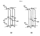
- Figure 6 shows other embodiments of the coil device of this invention, in which the coil has different shapes.
- the figure omits condensers and shows only conductors.
- the condensers and feeding methods in various configurations or with various modifications as explained in the embodiments shown in figures 2 - 5 can be applied as appropriately.
- the coil 601 shown in Figure 6(a) is made by deforming the cylindrical coil almost to the circular truncated cone shape. Even with the coil 601, it is possible to obtain similar sensitivity distribution and tuning frequency to those of the coil shown in Figure 2, only by slightly adjusting the value of condenser and others.
- the coil 602 shown in Figure 6(b) is made by combining two coils deformed to the circular truncated cone shape, and has uniform sensitivity at the central part of these two coils. When they are employed as an RF coil in the MRI apparatus, therefore, they can be disposed to sandwich the subject horizontally or vertically to obtain highly sensitive information on the central part of the subject.
- This coil 602 can be applied to the horizontal magnetic field MRI apparatus like a cylindrical coil or the coil 601 in the shape of circular truncated cone shown in Figure 6 (a), but is also applicable to the vertical magnetic field MRI apparatus.
- the coil 603 shown in Figure 6(c) is made by further deforming the coil 602 shown in Figure 6(b) to a complete plane shape, and like the coil 602 shown in Figure 6(b) two of the coil 603 can be disposed to face each other.
- This coil 603 has an excellent sensitivity to the electromagnetic waves which are almost parallel to the planar coil surface and is preferably applicable to the vertical magnetic field MRI apparatus. It is applicable most preferably to the MRI apparatus equipped with static magnetic field magnets, called open MRI apparatus.
- the second embodiment of the MRI apparatus of the present invention is explained below.
- the MRI apparatus shown in Figure 1 uses the coil device of the present invention as a transmitting-receiving RF coil.
- the MRI apparatus of this embodiment equipped with a receive only coil and a transmit only coil may use the coil device of the present invention as a receive only coil and/or transmit only coil.
- Figure 7 illustrates the configuration where the coil device of the present invention is used as the transmit only coil 701 or the receive only coil 702 for the MRI apparatus. Since the magnet which generates static magnetic fields, the magnet which generates gradient magnetic fields, the power supply for the gradient magnetic field and the display are installed in the same way as in Figure 1, they are not shown in Figure 7.
- the RF coils 701 and 702 are disposed on a static magnetic field.
- the RF coil 701 is a transmitting coil and is connected with the transmitter 704.
- the RF coil 702 is a receiving coil and connected with the receiver 703.
- the receiver 703 and the transmitter 704 are connected with the data processing and operating part 705.
- the receive only coil 702 comprises the coil device of the present invention as shown in figures 2 - 5.
- the RF coil 701 can be configured by, for example, the publicly known bird cage type coil or multiple patch resonator type coil.
- the multiple number of first coils connected with the second coils made of two ring-shaped parts are disposed spaced each other to allow the invasion of electromagnetic wave from outside. Consequently, without preventing transmission by the RF coil 701, electromagnetic wave can be irradiated from the RF coil 701 inside the subject equipped with the receive only coil 702. In this case, nuclear magnetic resonance signals can be received in a tuning mode at the frequencies corresponding to that of the electromagnetic waves irradiated from the RF coil 701.
- the coil device of the present invention can be used as a transmit only coil 701. In this case, by using two different coils with a tuning mode at different frequencies as the receive only coil 702, different nuclides can be tested. Further, since the coil device of the present invention has a great flexibility in adjusting frequency, the coil with different sizes and shapes can be configures by adjusting the capacity of condenser to be inserted into the first conducting and the second conducting sections of the first coil and the capacity of condenser to be inserted into the ring-shaped conducting section of the second coil. Therefore, the coil device of the present invention can be used as the transmit only coil 701 and the receive only coil 702 for the same MRI apparatus. This may ease the testing of two nuclides without complicating the equipment or exchanging coils.
- the coil was designed to have an axial length of 220 millimeter, outer diameter of about 334 millimeter and internal diameter of approximately 276 millimeter. Also, the value, C1, of the first condenser 207 sandwiched between the first conducting sections of the first coil was set at 17pF, and the value, C2, of the condenser 208 between second conducting sections was set at 12pF. Since the use of a copper rod of 4 millimeter in radius is assumed, the electric conductivity of copper was used.
- Resonance characteristics of this RF coil obtained by simulation are shown in Figure 8, where the horizontal and vertical axes represent the frequency and the impedance, respectively.
- the impedance was obtained by simulating the case in which linear polarized feeding wave was fed only from a condenser disposed at the first conducting section of the first coil.
- the RF coil of the present example shows the multiple number of peaks, of which 8 peaks appearing in the range between frequencies of 30 MHz and 110 MHz are resonance peaks characteristics to the low pass and bird cage type coil, while the peak 801 at about 32MHz is a tuning peak with highly uniform sensitivity over a large volume inside the coil.
- the frequency of 32 MHz corresponds to the tuning frequency of sodium or carbon in the MRI apparatus with the strength of static magnetic field of 3 Tesla.
- peaks seen near the higher frequency region from 125 to 143MHz are resonance peaks of the multiple patch resonator type coils.
- the number of resonance peak characteristics to the multiple patch resonator type coil is expressed by the formula, "the number of first coils/2 +1". Accordingly, the RF coil consisting of 16 first coils is estimated to have 9 peaks.
- the peaks 802 second lowest peaks at 129 MHz are tuning peaks with uniform sensitivity over a large volume inside the coil region.
- the frequency of 129 MHz corresponds to the tuning frequency of hydrogen in the 3 Tesla MRI apparatus.
- the picture 901 is a sensitivity map at the bird cage type tuning point of 32 MHz
- the picture 902 is a sensitivity map at the multiple patch resonator type tuning point of 129 MHz.
- the unit of contour in the sensitivity map is A/ (m ⁇ W).
- the graphs illustrated right-side each sensitivity map show the sensitivity distribution at one cross section surface.
- the birdcage type sensitivity map 901 shows uniform sensitivity of 6 - 7 at the central part. This is the characteristic sensitivity distribution of the bird cage type coil characteristic in the circular polarized feeding.
- the multiple patch resonator type sensitivity map 902 shows uniform sensitivity of about 0.7 near the center. In this case, a relatively strong sensitivity of about 3 is shown in the donut-shaped space sandwiched between the first and the second conducting sections of the first coil constituting the RF coil, actually also in thick cylindrical space. This donut-shaped sensitivity is characteristic to the resonance of multiple patch resonator type.
- the RF coil of the present invention could generate uniform sensitivity of bird cage and multiple patch resonator types at two frequencies of 32 MHz and 128 MHz. It is known that the multiple patch resonator type has much freedom in the coil design especially in capacitor setting values than the bird cage type in the high magnetic field MRI apparatus and has higher sensitivity. The fact that the tuning in the higher frequency range is of multiple patch resonator type in the present invention indicates its usefulness in the coil production for the high magnetic field MRI apparatus.
- the values of the condensers, C1 and C2, shown in this example are 12pF and 17pF, respectively.
- two tuning frequencies can be widely varied by changing these values.
- the tuning frequency of bird cage type can be changed to the higher frequency range by hardly changing the multiple patch resonator type tuning frequency.
- This example explains concrete configuration of dual-frequency tuning coil which can be tuned with the frequencies of hydrogen and phosphor in the 3-Tesla MRI apparatus as in Example 1.
- the RF coil of this example is, as in Example 1, the RF coil in the shape shown in Figure 2. However, it is different from Example 1 in that the condenser 301 is inserted into the ring-shaped part of the second coil and its value was set at 250pF. As mentioned earlier, by inserting the condenser into the ring-shaped part of the second coil, the tuning frequency of bird cage type can be raised. The simulation of resonance characteristics of the RF coil of this example revealed that the addition of the condenser 301 of 250pF into the ring-shaped part of the RF coil in Example 1 could alter the bird cage type tuning frequency from 32MHz to 52MHz while maintaining the multiple patch resonator type tuning frequency at 129MHz.
- the frequency of 52 MHz is almost identical with the tuning frequency of phosphor in the 3-Tesla MRI apparatus. It was also shown that by using the coil configuration of the present invention, a coil having dual frequency tuning corresponding to the frequencies of hydrogen and phosphor could be configured. Similarly, the dual frequency tuning coil, which can correspond to both hydrogen and other nuclide, or other two nuclides, can be configured.
- Resonance characteristics of the RF coil in which two conducting parts of the first conducting section connected via the condenser 207 are connected with one conductor into one conductor without using the condenser 207 in Example 2, was examined. Other elements of the configuration were same with those of Example 2. Feeding was performed in parallel with the condenser 208 or 301 among the multiple number of condensers.
- the value C2 of the condenser 208 inserted into the second conducting section (inside the rung) is set at 5.8pF, and the value of the condenser 301 of the second coil (ring part) at 119.7pF, a dual frequency tuning coil which is adapted to the frequencies of hydrogen and phosphor could be configured.
- the RF coil of this example has an advantage that the configuration may be simplified because the condenser 207 can be omitted.
- the RF coil of the present invention has dual tuning modes with a single coil, and can receive and/or transmit two different signals of different frequencies.
- This coil device is applicable as a part of the MRI apparatus as well as to all kinds of devices which use electromagnetic frequencies in the range of several MHz to several GHz frequencies.
Landscapes
- Physics & Mathematics (AREA)
- Condensed Matter Physics & Semiconductors (AREA)
- General Physics & Mathematics (AREA)
- Magnetic Resonance Imaging Apparatus (AREA)
Applications Claiming Priority (1)
| Application Number | Priority Date | Filing Date | Title |
|---|---|---|---|
| JP2006304009A JP4869029B2 (ja) | 2006-11-09 | 2006-11-09 | コイル装置及びそれを用いた磁気共鳴検査装置 |
Publications (1)
| Publication Number | Publication Date |
|---|---|
| EP1921461A1 true EP1921461A1 (fr) | 2008-05-14 |
Family
ID=39046794
Family Applications (1)
| Application Number | Title | Priority Date | Filing Date |
|---|---|---|---|
| EP07021565A Ceased EP1921461A1 (fr) | 2006-11-09 | 2007-11-06 | Bobine de type cage d'oiseau à double accord pour l'IRM |
Country Status (3)
| Country | Link |
|---|---|
| US (1) | US7589530B2 (fr) |
| EP (1) | EP1921461A1 (fr) |
| JP (1) | JP4869029B2 (fr) |
Cited By (1)
| Publication number | Priority date | Publication date | Assignee | Title |
|---|---|---|---|---|
| CN103412271A (zh) * | 2013-05-08 | 2013-11-27 | 深圳市特深电气有限公司 | 多通道核磁共振线圈 |
Families Citing this family (14)
| Publication number | Priority date | Publication date | Assignee | Title |
|---|---|---|---|---|
| JP4879811B2 (ja) * | 2007-04-23 | 2012-02-22 | 株式会社日立製作所 | コイル装置及びそれを用いた磁気共鳴検査装置 |
| US20110018539A1 (en) * | 2007-08-03 | 2011-01-27 | Raju Viswanathan | Hybrid imaging coils for magnetic resonance imaging |
| GB0905768D0 (en) * | 2009-04-03 | 2009-05-20 | Siemens Ag | Antenna feed |
| KR101453297B1 (ko) | 2011-08-19 | 2014-10-22 | 삼성전자주식회사 | 복수 타입의 자기 공명 영상들을 동시에 생성하는 장치 및 방법 |
| BR112014028136A2 (pt) * | 2012-05-14 | 2017-06-27 | Koninklijke Philips Nv | disposição de circuito de alimentação, sistema transmissor paralelo, e, método de comutação dos elementos de bobina de um sistema transmissor paralelo |
| JP5897415B2 (ja) * | 2012-06-29 | 2016-03-30 | ジーイー・メディカル・システムズ・グローバル・テクノロジー・カンパニー・エルエルシー | 磁気共鳴装置およびプログラム |
| US10126382B2 (en) | 2012-11-06 | 2018-11-13 | Hitachi, Ltd. | Magnetic resonance imaging apparatus and antenna device |
| KR101424976B1 (ko) * | 2012-11-08 | 2014-08-13 | 삼성전자주식회사 | 위상 배열형 고주파 코일 및 이를 채용한 자기공명영상 장치 |
| US10976389B2 (en) | 2014-01-03 | 2021-04-13 | Samsung Electronics Co., Ltd. | Radiofrequency coil |
| KR101714454B1 (ko) | 2016-04-29 | 2017-03-10 | 가천대학교 산학협력단 | 나선형 모노폴 안테나 구조의 자기공명 영상 장치 |
| JP6887346B2 (ja) * | 2017-08-29 | 2021-06-16 | 株式会社日立製作所 | 高周波コイルユニット及び磁気共鳴イメージング装置 |
| SG11202109090SA (en) * | 2019-02-22 | 2021-09-29 | Promaxo Inc | Pseudo-birdcage coil with variable tuning and applications thereof |
| WO2020172673A1 (fr) * | 2019-02-22 | 2020-08-27 | Promaxo, Inc. | Systèmes et procédés de réalisation d'une imagerie par résonance magnétique |
| EP3800478A1 (fr) * | 2019-10-06 | 2021-04-07 | Université catholique de Louvain | Antenne de cage à oiseaux améliorée |
Citations (6)
| Publication number | Priority date | Publication date | Assignee | Title |
|---|---|---|---|---|
| JPH0531092A (ja) * | 1991-07-31 | 1993-02-09 | Toshiba Corp | 磁気共鳴映像装置用高周波プローブおよび磁気共鳴映像装置 |
| US5777474A (en) | 1996-11-08 | 1998-07-07 | Advanced Imaging Research, Inc. | Radio-frequency coil and method for resonance imaging/analysis |
| JPH1189812A (ja) | 1997-09-16 | 1999-04-06 | Technol Res Assoc Of Medical & Welfare Apparatus | 磁気共鳴映像装置用多重同調型高周波コイル |
| JP2001145608A (ja) | 1999-11-19 | 2001-05-29 | Ge Yokogawa Medical Systems Ltd | バードケージ・コイル |
| US6806710B1 (en) | 1999-04-01 | 2004-10-19 | Siemens Aktiengesellschaft | Magnetic resonance antenna |
| WO2005050239A1 (fr) * | 2003-11-18 | 2005-06-02 | Koninklijke Philips Electronics, N.V. | Systeme de bobinage hf pour irm shf |
Family Cites Families (12)
| Publication number | Priority date | Publication date | Assignee | Title |
|---|---|---|---|---|
| US4692705A (en) * | 1983-12-23 | 1987-09-08 | General Electric Company | Radio frequency field coil for NMR |
| US4916418A (en) | 1989-03-31 | 1990-04-10 | Varian Associates, Inc. | Double tuned bird cage coil |
| JP3147418B2 (ja) * | 1991-08-09 | 2001-03-19 | 株式会社日立製作所 | Mri用rfコイル |
| US5557247A (en) | 1993-08-06 | 1996-09-17 | Uab Research Foundation | Radio frequency volume coils for imaging and spectroscopy |
| US6100694A (en) | 1999-02-24 | 2000-08-08 | Varian, Inc. | Multiple-tuned bird cage coils |
| JP4350889B2 (ja) * | 2000-12-27 | 2009-10-21 | 株式会社日立メディコ | 高周波コイル及び磁気共鳴イメージング装置 |
| US6788058B1 (en) * | 2001-03-08 | 2004-09-07 | General Electric Company | Asymmetric ring dome radio frequency coil |
| AU2003302444A1 (en) * | 2002-11-27 | 2004-06-18 | Koninklijke Philips Electronics N.V. | Degenerate birdcage coil and transmit/receive apparatus and method for same |
| JP3954059B2 (ja) * | 2004-10-21 | 2007-08-08 | シャープ株式会社 | 発振器、通信装置 |
| WO2006076739A2 (fr) * | 2005-01-14 | 2006-07-20 | Invivo Corporation | Bobine de tete a champ eleve pour un fonctionnement a double mode dans une imagerie a resonance magnetique |
| JP2007325826A (ja) * | 2006-06-09 | 2007-12-20 | Hitachi Ltd | 2重同調rfコイル |
| JP4844310B2 (ja) * | 2006-09-13 | 2011-12-28 | 株式会社日立製作所 | 高周波コイルおよび磁気共鳴撮像装置 |
-
2006
- 2006-11-09 JP JP2006304009A patent/JP4869029B2/ja not_active Expired - Fee Related
-
2007
- 2007-11-06 EP EP07021565A patent/EP1921461A1/fr not_active Ceased
- 2007-11-08 US US11/936,885 patent/US7589530B2/en not_active Expired - Fee Related
Patent Citations (6)
| Publication number | Priority date | Publication date | Assignee | Title |
|---|---|---|---|---|
| JPH0531092A (ja) * | 1991-07-31 | 1993-02-09 | Toshiba Corp | 磁気共鳴映像装置用高周波プローブおよび磁気共鳴映像装置 |
| US5777474A (en) | 1996-11-08 | 1998-07-07 | Advanced Imaging Research, Inc. | Radio-frequency coil and method for resonance imaging/analysis |
| JPH1189812A (ja) | 1997-09-16 | 1999-04-06 | Technol Res Assoc Of Medical & Welfare Apparatus | 磁気共鳴映像装置用多重同調型高周波コイル |
| US6806710B1 (en) | 1999-04-01 | 2004-10-19 | Siemens Aktiengesellschaft | Magnetic resonance antenna |
| JP2001145608A (ja) | 1999-11-19 | 2001-05-29 | Ge Yokogawa Medical Systems Ltd | バードケージ・コイル |
| WO2005050239A1 (fr) * | 2003-11-18 | 2005-06-02 | Koninklijke Philips Electronics, N.V. | Systeme de bobinage hf pour irm shf |
Cited By (2)
| Publication number | Priority date | Publication date | Assignee | Title |
|---|---|---|---|---|
| CN103412271A (zh) * | 2013-05-08 | 2013-11-27 | 深圳市特深电气有限公司 | 多通道核磁共振线圈 |
| CN103412271B (zh) * | 2013-05-08 | 2016-03-30 | 深圳市特深电气有限公司 | 多通道核磁共振线圈 |
Also Published As
| Publication number | Publication date |
|---|---|
| US20080150533A1 (en) | 2008-06-26 |
| JP4869029B2 (ja) | 2012-02-01 |
| US7589530B2 (en) | 2009-09-15 |
| JP2008119091A (ja) | 2008-05-29 |
Similar Documents
| Publication | Publication Date | Title |
|---|---|---|
| US7589530B2 (en) | Coil device and nuclear magnetic resonance imaging apparatus using the same | |
| KR100677021B1 (ko) | Rf바디 코일 | |
| US8380266B2 (en) | Coil element decoupling for MRI | |
| JP6402112B2 (ja) | 磁気共鳴イメージングのためのzセグメント化されたラジオ周波数アンテナ装置 | |
| US7639012B2 (en) | Coil apparatus and magnetic resonance imaging apparatus using the same | |
| CN104698411B (zh) | 用于开放式磁共振成像系统的多通道射频线圈 | |
| CN111133326A (zh) | 用于同时成像和b0匀场的磁共振线圈 | |
| US20100253347A1 (en) | Antenna system and magnetic resonance imaging apparatus | |
| US7508210B2 (en) | Short element TEM coil for ultra-high field MR | |
| EP1883348B1 (fr) | Dispositif d'antenne pour capter des signaux à résonance magnétique fournie avec sa propre unité de communication | |
| KR101709724B1 (ko) | 자기공명영상용 다중 주파수 RF(radio frequency) 코일 어셈블리 및 자기공명영상 시스템 | |
| US11237233B2 (en) | Self-decoupled RF coil array for MRI | |
| US6795037B2 (en) | Radio-frequency antenna for a magnetic resonance system | |
| EP0304249B1 (fr) | Méthode et appareil pour la résonance magnétique | |
| CN114631033B (zh) | 具有多个独立的发送接收通道的磁共振体积线圈 | |
| US7619412B2 (en) | MRI apparatus and high-frequency coil with plural imaging regions | |
| US20080161675A1 (en) | Ultra-Short Mri Body Coil | |
| CN114280515B (zh) | 高频线圈单元以及磁共振成像装置 | |
| KR20150145105A (ko) | 고주파 표면 코일 및 이를 채용한 자기 공명 장치 | |
| JP2022521611A (ja) | コイル配列、コイル配列を備えるmrシステム、特にmriおよび/またはmrsシステムおよびコイル配列の使用 | |
| Ryu | Preliminary Results of 7-Channel Insertional pTx Array Coil for 3T MRI |
Legal Events
| Date | Code | Title | Description |
|---|---|---|---|
| PUAI | Public reference made under article 153(3) epc to a published international application that has entered the european phase |
Free format text: ORIGINAL CODE: 0009012 |
|
| 17P | Request for examination filed |
Effective date: 20080331 |
|
| AK | Designated contracting states |
Kind code of ref document: A1 Designated state(s): AT BE BG CH CY CZ DE DK EE ES FI FR GB GR HU IE IS IT LI LT LU LV MC MT NL PL PT RO SE SI SK TR |
|
| AX | Request for extension of the european patent |
Extension state: AL BA HR MK RS |
|
| AKX | Designation fees paid |
Designated state(s): DE FR GB IT |
|
| 17Q | First examination report despatched |
Effective date: 20120223 |
|
| STAA | Information on the status of an ep patent application or granted ep patent |
Free format text: STATUS: THE APPLICATION HAS BEEN REFUSED |
|
| 18R | Application refused |
Effective date: 20121218 |