EP1921604B1 - Generator für digitale Audiosignale mit Umgebungsgeräuschen - Google Patents
Generator für digitale Audiosignale mit Umgebungsgeräuschen Download PDFInfo
- Publication number
- EP1921604B1 EP1921604B1 EP07254402.6A EP07254402A EP1921604B1 EP 1921604 B1 EP1921604 B1 EP 1921604B1 EP 07254402 A EP07254402 A EP 07254402A EP 1921604 B1 EP1921604 B1 EP 1921604B1
- Authority
- EP
- European Patent Office
- Prior art keywords
- outputs
- reverberation
- reflection
- produce
- output
- Prior art date
- Legal status (The legal status is an assumption and is not a legal conclusion. Google has not performed a legal analysis and makes no representation as to the accuracy of the status listed.)
- Not-in-force
Links
- 230000005236 sound signal Effects 0.000 title claims description 39
- 230000007613 environmental effect Effects 0.000 title description 3
- 230000004044 response Effects 0.000 claims description 51
- 230000003111 delayed effect Effects 0.000 claims description 39
- 238000000034 method Methods 0.000 claims description 29
- 238000001914 filtration Methods 0.000 claims description 15
- 230000001934 delay Effects 0.000 claims description 5
- 238000007781 pre-processing Methods 0.000 claims description 3
- 238000012545 processing Methods 0.000 description 25
- 239000011159 matrix material Substances 0.000 description 13
- 238000010586 diagram Methods 0.000 description 10
- 230000000694 effects Effects 0.000 description 10
- 238000002592 echocardiography Methods 0.000 description 8
- 238000009792 diffusion process Methods 0.000 description 5
- 239000013598 vector Substances 0.000 description 4
- 238000007796 conventional method Methods 0.000 description 3
- 230000001419 dependent effect Effects 0.000 description 3
- 230000004075 alteration Effects 0.000 description 2
- 238000013461 design Methods 0.000 description 2
- 238000013507 mapping Methods 0.000 description 2
- 238000010079 rubber tapping Methods 0.000 description 2
- 230000002123 temporal effect Effects 0.000 description 2
- 238000010521 absorption reaction Methods 0.000 description 1
- 238000007792 addition Methods 0.000 description 1
- 230000003321 amplification Effects 0.000 description 1
- 230000002238 attenuated effect Effects 0.000 description 1
- 239000000872 buffer Substances 0.000 description 1
- 238000004891 communication Methods 0.000 description 1
- 210000005069 ears Anatomy 0.000 description 1
- 238000005259 measurement Methods 0.000 description 1
- 238000003199 nucleic acid amplification method Methods 0.000 description 1
- 230000003287 optical effect Effects 0.000 description 1
- 238000013139 quantization Methods 0.000 description 1
- 238000005070 sampling Methods 0.000 description 1
- 238000001228 spectrum Methods 0.000 description 1
- 238000006467 substitution reaction Methods 0.000 description 1
Images





Classifications
-
- G—PHYSICS
- G10—MUSICAL INSTRUMENTS; ACOUSTICS
- G10K—SOUND-PRODUCING DEVICES; METHODS OR DEVICES FOR PROTECTING AGAINST, OR FOR DAMPING, NOISE OR OTHER ACOUSTIC WAVES IN GENERAL; ACOUSTICS NOT OTHERWISE PROVIDED FOR
- G10K15/00—Acoustics not otherwise provided for
- G10K15/08—Arrangements for producing a reverberation or echo sound
- G10K15/12—Arrangements for producing a reverberation or echo sound using electronic time-delay networks
Definitions
- the disclosure relates generally to audio signal processing, and in particular to generating environmental reverberation effects for digital audio content.
- Artificial reverberations are often added to dry audio contents to simulate effects of real or virtual environments.
- artificial reverberations are added to give the listeners a sense of being in the real environments, such as a concert hall, an auditorium, etc.
- reverberations are echoes bounced back at different time instants from the surrounding environment, such as a room.
- the ideal way of generating reverberations would be convolving the audio signal with the impulse response of the desired environment.
- Such conventional methods are formulated by treating the environment as a linear time-invariant system whose characteristics are completely specified by its impulse response. However, such methods are difficult to implement.
- a number of conventional methods have been proposed to approximate the exact reverberation response or to create only the salient signals.
- Some of the algorithms use feedback loops with delay lines, sometimes combined with all-pass filters.
- One drawback of such feedback systems is that they typically create resonances that colorize the sound.
- Such problems are overcome by phase-shifting or time-variant delay lines in some algorithms, which may introduce certain undesired pitch shifting effects.
- Some algorithms use only delay lines and feed forward loops, tapping at different locations of the delay lines.
- Some other conventional algorithms separate the reverberation into early and late parts and generate them separately. This typically leads to a sudden increase of echo density at the boundary, which is not true in a natural environment. Attempts based on modeling techniques have also been reported in the literature.
- a number of conventional methods have been proposed to approximate the exact reverberation response or to create only the salient signals.
- Some of the algorithms use feedback loops with delay lines, sometimes combined with all-pass filters.
- One drawback of such feedback systems is that they typically create resonances that colorize the sound.
- Such problems are overcome by phase-shifting or time-variant delay lines in some algorithms, which may introduce certain undesired pitch shifting effects.
- Some algorithms use only delay lines and feed forward loops, tapping at different locations of the delay lines.
- Some other conventional algorithms separate the reverberation into early and late parts and generate them separately. This typically leads to a sudden increase of echo density at the boundary, which is not true in a natural environment. Attempts based on modeling techniques have also been reported in the literature.
- US4535474 describes an ambience simulating apparatus having a mixer for combining a plurality of at least two electrical analog signal representations of audio signals into a single analog signal, digitizing circuits for digitizing said single analog signal, a memory for storing the digital representation of said analog signal, and circuitry for selectively collecting, attenuating, and combining portions of the data stored in the memory, whereby a signal can be produced which represents the combination of a plurality of delayed and attenuated audio signals which when reproduced as an audio signal in combination with the reproduction of the audio signals from said plurality of electrical analog signals, creates a fullness of sound referred to as ambience.
- US2006045283 describes a method and related apparatus for generating an output signal with audio reverberation effect according to an input signal.
- US4803731 describes a reverberation imparting device comprises a delay memory storing input signal data at a predetermined sampling period and producing a delay signal corresponding to time interval between writing of the input signal data and reading thereof, a plurality of address each adding delay signals read out from the delay memory, and an output section for delivering out an output of each of the adders as a reverberation signal.
- US2004213416 describes a reverberation processor comprising a plurality of delay lines implemented in delay line memory, and hardware operable to introduce an echo effect into the reverberation decay and to provide a control parameter to control salience of the echo effect.
- Embodiments of the present disclosure solve the problem of generating environmental reverberation effects controlled by parameters describing the characteristics of the environment's reverberation response.
- the reverberations generated sound natural with little coloration and give the sense of spaciousness of the desired environment.
- the method is easily controlled to simulate different environments.
- the present disclosure provides a method of generating reverberations using a uniform structure to generate reverberations controlled by a plurality of descriptive characteristics (parameters) either extracted from real environments or completely specified as wish.
- a device comprising a reverberation controller operable to: pre-process one or more predetermined characteristics of a first audio signal to produce a pre-processed signal; generate a plurality of delayed outputs from the pre-processed signal, each output having a predetermined delay; and produce a plurality of reflection outputs from the plurality of delayed outputs; and to combine the plurality of reflection outputs to produce a second audio signal having a desired reverberation response, wherein the reverberation controller is operable to produce the plurality of reflection outputs by: summing a plurality of feedback outputs and the plurality of delayed outputs to produce a plurality of summed outputs; and producing the plurality of feedback outputs and the plurality of reflection outputs from the plurality of summed outputs, characterized wherein the reverberation controller is operable to produce the plurality of feedback outputs and the plurality of reflection outputs from the plurality of summed outputs by: filtering
- a method of producing a desired reverberation response to an audio signal comprising: pre-processing one or more predetermined characteristics of a first audio signal to produce a pre-processed signal; generating a plurality of delayed outputs from the pre-processed signal, each output having a predetermined delay; and producing a plurality of reflection outputs from the plurality of delayed outputs; and combining the plurality of reflection outputs to produce a second audio signal having a desired reverberation
- producing the plurality of reflection outputs from the plurality of delayed outputs comprises: summing a plurality of feedback outputs and the plurality of delayed outputs to produce a plurality of summed outputs; and the method is characterized by producing the plurality of feedback outputs and the plurality of reflection outputs from the plurality of summed outputs by: filtering summed outputs to produce the reflection outputs; filtering the reflection outputs to produce filtered reflection outputs; delaying the filtered reflection outputs
- a system comprising: an audio source; an audio output; a control unit, operable to receive information from a user, the information relating to a desired reverberation response; and a reverberation generator coupled to the audio source, the audio output, and the controlling unit, the reverberation generator comprising a reverberation controller according to the first aspect, operable to: pre-process one or more selected characteristics of a first audio signal from the audio source to produce the pre-processed signal and to produce the second audio signal to the audio output.
- DSP digital signal processing
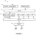
- FIGURE 1 A typical structure of a digital signal processor 100, especially for audio signals, is shown in FIGURE 1 .
- the audio data is input and output using a digital I/O interface 102.
- a computational unit 104 loads input audio data and program data to its own registers, processes the stored audio data, and sends the processed audio data back to the I/O interface for output.
- Computation typically consists of additions, subtractions, multiplications and other operations. Multiplications typically needs more resources than other operations. Typically, short filter lengths and fewer multiplications will reduce the processing load of the processor.
- a controller 106 is typically present to control the processor through host registers 108 which are interfaced with the computational unit 104 through a data bus 110.
- FIGURE 2 An example of a system or device 200 having a reverberation generator 201 is shown in FIGURE 2 .
- Audio content received at an audio input port 203 from an audio source 202 is first decoded by a decoder 204 to produce an uncompressed stream 206, in some embodiments in pulse code modulation (PCM) format.
- PCM pulse code modulation
- the audio source 202 may be a radio receiver, a microphone, or other source of a live audio signal; an optical, electronic or magnetic storage medium or other source of a stored audio signal; or any other source of an audio signal.
- the stream 206 is passed to a reverberation generator 208 as input.
- the reverberation controller 208 generates reverberations as specified by a controlling unit 210 that may in turn take in the information relating to a desired reverberation response via a user interface 212, producing a reverberated output 214 that is passed to an output port 216 or a further processing unit.
- a flow of information mapping 300 is depicted in FIGURE 3 .
- a reverberation model representing a desired reverberation response is established by extracting certain important descriptive characteristics (parameters) 304 of the reverberations from a desired environment 302. Extracted parameters are passed to the reverberation generator or controller to configure its internal controlling parameters 306 to generate the desired reverberation response. How to extract the descriptive parameters from the environment to map into the reverberation model is beyond the scope of this disclosure.
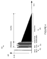
- FIGURE 4 shows an amplitude response 400 of a typical environment.
- the reverberation response model 400 comprises three temporal components: a direct signal 402, early reflections 404, and late reverbs 406.
- the direct signal 402 reaches the listener's ears first and is followed by the echoes 404 caused by reflections bounced back from the surroundings, for example, walls, doors.
- the reverberation generally shows certain characteristics: the early echoes 404 are quite sparse after the direct sound; the density of the echoes increases over time and in the late part of the reverberation 406, the echoes become so highly diffused and dense that they sound like random noise. How fast the density of the echoes is built up generally depends on the room size. The smaller a room is, the faster the density of the echoes will be built up. The rate of decay of the overall energy level of the echoes also varies depending on the absorption of the surfaces of the room.
- the reflection surfaces generally absorb more high-frequency signals than low-frequency signals.
- high-frequency signals decay faster than low-frequency signals.
- How fast high frequency signals decay with respect to low-frequency signals depends on the surfaces of reflections. However, this is not necessarily the case when virtual environments are being simulated. In such applications as computer games, it may be so designed that low frequencies are being absorbed faster than high frequencies are. Hence the decay time may be frequency-dependent.
- the reverberation response in this model in fact describes the response at the listener's position for a particular position of the source, assuming that both are in the same environment. Hence, in general, not only does the reverberation response depend on the environment, but also depends on the absolute positions of both listener and source.
- a desired reverberation response may be characterized by, for example, the following set of parameters: (1) Intensity or a power of the whole response; (2) High Frequency (HF) Intensity Ratio or an attenuation at a reference high frequency (Reference HF) relative to DC; (3) Reflection Intensity or a power of early reflections; (4) Reverb Intensity or a power of late reverbs; (5) Reflection Delay or a delay time of a first reflection relative to a direct signal; (6) Reverb Delay or a delay time of an onset of late reverberation relative to a first reflection; (7) Decay Time or a reverberation decay time at low frequencies; (8) Decay Time HF Ratio or a ratio of decay time at high frequencies relative to decay time at low frequencies; (9) Diffusion Factor or an echo density of late reverberations; (10) Modal Density Factor or a modal density
- the method proposed in the present disclosure generates reverberations controlled by parameters as these, which offer increased flexibility in creating real or virtual environments.
- a computational cost of implementing an embodiment of the present disclosure using digital signal processing may be reasonably low due to factors such as: (1) a design involving few multiplications; (2) delay lines realized by circular buffers; and (3) filters implemented as first order IIR filters.
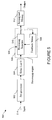
- FIGURE 5 A high-level functional block diagram of a reverberation controller 500 embodying the present disclosure is shown in FIGURE 5 . Each block is separately detailed in FIGURE 6 to FIGURE 11 . Typically one or more modules are affected by each descriptive parameter of the reverberation model, and together the modules generate a reverberation response that matches a desired environment.
- a pre-processor 502 prepares an input signal 514 and passes it to a tapped delay line (DL0) 504, which has N unevenly spaced reading taps.
- a processing engine module 505 takes the form of a feedback delay network (FDN) 506 that consists of a feedback matrix 508 and a bank of processing branches 510.
- the signals read from DL0 504 are summed with the feedback signals from the end of FDN 506 before entering the processing branches 510.
- the processing branches 510 all-pass filter, low-/high-pass filter, delay and attenuate their respective inputs, and then the processed signals are multiplied with the feedback matrix 508 to feed back to the beginning of the FDN 506. Reflections and reverbs are gathered from within the processing branches 510 and routed to respective routing and mixing modules 512.
- reverbs may be differentially delayed before mixing.
- the final output is formed by summing up the mixed reflections and the mixed reverbs. Having gone through many stages of filtering, delay and feedback, the reverberation is very natural sounding with little coloration. Since each stage only requires very simple operations such as low-order filtering, the total computational complexity is quite low. The memory required for a reasonably large range of each parameter is also quite minimal, as will be detailed in the next section.
- a reverberation controller can be configured by a set of descriptive parameters as described above.
- Such a reverberation controller may have one or two input channels, and may produce two outputs.
- one descriptive parameter may affect one or more modules of the proposed method.
- the pre-processor module includes
- a pre-processor module 502 is depicted in FIGURE 6 .
- a down-mix/bypass module 604 may work in a down-mix mode, combining the two input channels to produce a single stream, denoted as S.
- the down-mix/bypass module 604 may be bypassed such that S is identical to input.
- S is then multiplied with Room Gain 606, which may be determined by Intensity, to control the overall intensity level of the reverberation.
- S is then passed through a Low-pass Filter (LPF) 608 to attenuate the intensity at the reference high frequency.
- LPF Low-pass Filter
- the LPF is determined by HF Intensity Ratio and Reference HF, and typically it may be as simple a filter as a 1st order IIR filter. Since both multiplying by a gain and filtering are linear operations, the exact order of them does not matter. That is, the output is theoretically the same if LPF comes before the gain.
- the pre-processed stream S is fed into a tapped delay line (DL0) 504 one embodiment of which is depicted in FIGURE 7 .
- DL0 504 has N unevenly spaced reading taps 702, where N is the number of processing branches 510 of the processing engine module 505. Feeding the processing engine module 505 with unevenly spaced taps may increase the echo density while minimizing coloration.
- the offset of the first (earliest) tap may be determined by the value of Reflection Delay, which may be up to 0.3 seconds, and the spacing between successive reading taps is uneven and may change proportionally to the value of Reverb Delay.
- the distance between the last (latest) reading tap and the first reading tap is preferably in the range of 0.002 seconds to 0.025 seconds, where the lower bound of 0.002 seconds corresponds to extremely short Reverb Delay and the upper bound of 0.025 seconds to extremely long Reverb Delay.
- An embodiment for the processing engine module 505 can be realized by a Feedback Delay Network (FDN) 506, as depicted in FIGURE 8 .
- FDN 506 consists of the N processing branches 510 and the feedback matrix 508.
- An exemplary processing branch 510a may be made up of an All-pass Filter (APF) 902, a Low-pass or High-pass Filter (LPF or HPF) 904, a delay line 906 and a gain 908, as depicted in FIGURE 9 .
- API All-pass Filter
- LPF or HPF Low-pass or High-pass Filter
- an input to processing branch 510i is the sum of an input read from reading tap i of DL0 504 and the ith element of the vector obtained by multiplying the feedback matrix 508 with delayed signals from the end of the processing branches 510.
- the APF 902 has a smoothly decaying impulse response and a flat frequency spectrum that introduces little coloration.
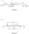
- An embodiment of the APF 902 is depicted in FIGURE 10 .
- the offsets of the reading taps to the delay lines in the APFs APF1-APFN may be proportional to the value of Reverb Delay, may be unevenly distributed, and may be chosen to be prime numbers.
- the shortest offset of the reading taps to the delay lines in the APFs APF1-APFN i.e., the effective delay
- the largest offset is preferably in the range of 1.2 to 1.5 times the shortest offset.
- the decay factors a of the APFs may be proportional to Decay Time and may also be unevenly distributed. In general, the longer the reading tap is, the smaller the decay factor a should be. A preferred range of a is recommended to be between 0.35 and 0.75.
- an APF may produce an infinite low level output even after input is removed, known as zero-input limit cycles. This may be eliminated by truncating the magnitude of stored values toward zero.
- the LPF/HPF 904 in the processing branch 510a may be used to control the Decay Time in a frequency-dependent manner.
- Decay Time HF Ratio is less than 1, the LPF 904 may be used to make shorter the decay time at high frequencies, and the smaller Decay Time HR Ratio is, the greater the low-pass filtering effect HPF should be.
- Decay Time HF Ratio is greater than 1, the HPF 904 may be used to make the decay time longer at high frequencies, and the greater Decay Time HR Ratio is, the greater the high-pass filtering effect HPF should be.
- Decay Time HF Ratio is equal to 1 the LPF/HPF 904 effectively degrades to a unit gain.
- Reference HF may be used in the design of the LPF/HPFs, which may be as simple as 1st order IIR filters.
- the delay lines 906 (DL1 ⁇ DLN) in individual processing branches 510 of the FDN 506 may control the modal density of the generated reverbs and the pace of reverbs' building up. The longer the delay lengths are, the higher the modal density is, but the slower the building up of reverbs.
- the offsets of the reading taps to the delay lines hence may be determined by Modal Density Factor and Reverb Delay jointly, may be unevenly distributed, and may be chosen be to prime numbers. At full capacity of Modal Density Factor, the smallest offset is preferably at least 45 milliseconds and not more than 100 milliseconds.
- the largest offset preferably does not exceed twice the length of the smallest.
- the reading taps may be randomized within a certain range centered at a chosen location. Before they are fed into the feedback matrix, the outputs of the DL's 906 (DL1 ⁇ DLN) are multiplied by respective gains 908 to achieve a desired Decay Time.
- the feedback matrix (FM) 508 may be a unitary matrix and controls the echo density of the late reverberation.
- the FM 508 may become sparser as Diffusion Factor becomes smaller. In one extreme, all elements of the FM 508 are non-zero values when the highest Diffusion Factor is desired; in the other extreme, the FM 508 becomes a diagonal matrix to cut off many feedback paths in response to a very low Diffusion Factor.
- the matrixed signals are combined with the signals 702 read from respective taps of DL0 and then fed into the beginning of the processing branches 510.
- inputs 1106 are collected from the taps after the APFs 902 in the FDN 506 as illustrated in FIGURE 9 .
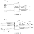
- a reflection mixing module 1102 and a reverb mixing module 1104 may produce reflections 1110 and reverbs 1112 respectively, and final outputs 1108 of the reverberation controller are obtained by summing up the reflections 1110 and reverbs 1112 on respective channels.
- One embodiment of the reflection mixing module 1102 consists of a matrix 1202 and two gains 1204 and 1206, as depicted in FIGURE 12 .
- the mixing matrix 1202 may be made of unit vectors orthogonal to each other, avoiding power amplification or attenuation and decorrelating outputs, and the mixed reflections may be multiplied by Reflection Gain to achieve the desired Reflection Intensity.
- FIGURE 13 One embodiment of the reverb mixing module 1104 is depicted in FIGURE 13 .
- Inputs 1302 are first differently delayed by Pre-reverb DLs 1304 before entering a mixing matrix 1306.
- the distribution of these delay lengths may be scaled proportionally to Reverb Delay, and the maximum delay length is preferably less than 30 milliseconds when Reverb Delay is at a maximum value.
- the reverb mixing matrix 1306 may be made up of unit vectors orthogonal to each other, and it controls the echo density, in addition to decorrelating the outputs. For high Diffusion Factor, its unit vectors may have more zeros to cut off more reverb paths; and vice versa.
- Mixed outputs 1308 of the matrix 1306 are multiplied by Reverb Gain to achieve a desired Reverb Intensity, and then may be further delayed by Post-reverb DLs 1312, whose reading taps may be determined by Reverb Delay.
- the present disclosure proposes a method to generate and control artificial reverberations with low cost in terms of computation and memory. It produces a natural sounding reverberation that provides the sense of spaciousness of the desired environment, as specified by the descriptive parameters of a well established reverberation model. The density of the generated reverberation increases over time and the decay time is frequency-dependent. Other properties (intensity levels, delays, etc.) are well controlled as specified.
- the reverberation is generated with a rather simple and uniform structure, which generates early reflections and late reverbs in a unified manner as the real environment does without abrupt boundary between early and late reflections.
- the proposed method generates decorrelated outputs on two channels with one- or two-channel input.
- Couple and its derivatives refer to any direct or indirect communication between two or more elements, whether or not those elements are in physical contact with one another.
- the term “or” is inclusive, meaning and/or.
- the phrases “associated with” and “associated therewith,” as well as derivatives thereof, may mean to include, be included within, interconnect with, contain, be contained within, connect to or with, couple to or with, be communicable with, cooperate with, interleave, juxtapose, be proximate to, be bound to or with, have, have a property of, or the like.
Landscapes
- Physics & Mathematics (AREA)
- Engineering & Computer Science (AREA)
- Acoustics & Sound (AREA)
- Multimedia (AREA)
- Stereophonic System (AREA)
Claims (17)
- Vorrichtung (200), die einen Nachhall-Controller (500) umfasst, der betreibbar ist:Eine oder mehrere Kennlinien eines ersten Audiosignals (514) vorzuverarbeiten, um ein vorverarbeitetes Signal zu produzieren;eine Vielzahl verzögerter Outputs (702) aus dem vorverarbeiteten Signal zu generieren, wobei jeder Output eine vorbestimmte Verzögerung hat; undeine Vielzahl von Reflexions-Outputs (1110) aus der Vielzahl von verzögerten Outputs zu produzieren;und die Vielzahl von Reflexions-Outputs zu kombinieren, um ein zweites Audiosignal (1108) zu produzieren, das eine erwünschte Nachhallreaktion aufweist, wobei der Nachhall-Controller (500) betreibbar ist, eine Vielzahl von Reflexions-Outputs (1110) durch Folgendes zu produzieren:Summieren einer Vielzahl von Feedback-Outputs und der Vielzahl von verzögerten Outputs, um eine Vielzahl summierter Outputs zu produzieren;dadurch gekennzeichnet, dass der Nachhall-Controller (500) betreibbar ist, die Vielzahl von Feedback-Outputs und die Vielzahl von Reflexion-Outputs aus der Vielzahl summierter Outputs zu produzieren, durch:Filtern der summierten Outputs, um die Reflexions-Outputs zu produzieren;Filtern der Reflexions-Outputs, um gefilterte Reflexions-Outputs zu produzieren;Verzögern der gefilterten Reflexions-Outputs, um verzögerte gefilterte Reflexions-Outputs zu produzieren; undSteuern jeweiliger Verstärkungen (908) der verzögerten gefilterten Reflexions-Outputs, um die Vielzahl von Feedback-Outputs zu produzieren.
- Vorrichtung (200) nach Anspruch 1, wobei der Controller (500) ferner betreibbar ist, eine oder mehrere vorbestimmte Kennlinien des ersten Audiosignals durch Folgendes vorzuverarbeiten:Steuern einer Verstärkung (606) des ersten Audiosignals (514); undFiltern hoher Frequenzen des ersten Audiosignals (514).
- Vorrichtung (200) nach Anspruch 2, wobei die Verstärkung (606) des ersten Audiosignals (514) gemäß einer erwünschten Leistung der erwünschten Nachhall-Reaktion gesteuert wird, und hohe Frequenzen des ersten Audiosignals werden gemäß einer erwünschten Dämpfung mit einer Referenzfrequenz relativ zu einer Dämpfung bei DC der erwünschten Nachhall-Reaktion gefiltert.
- Vorrichtung (200) nach irgendeinem vorhergehenden Anspruch, wobei die Verzögerungen der verzögerten Outputs gemäß einer erwünschten Leistung früher Reflexionen der erwünschten Nachhall-Reaktion bestimmt werden.
- Vorrichtung (200) nach Anspruch 1, wobei:Eine Abklingkennlinie des Reflexions-Outputs gemäß einer oder mehrerer einer erwünschten Verzögerungszeit eines Beginns späten Nachhalls relativ zu einer ersten Reflexion der erwünschten Nachhall-Reaktion und einer erwünschten Nachhall-Abklingzeit bei niedrigen Frequenzen der erwünschten Nachhall-Reaktion bestimmt wird;eine Kennlinie der gefilterten Reflexions-Outputs gemäß einem erwünschten Verhältnis von Abklingzeit bei hohen Frequenzen zur Abklingzeit bei niedrigen Frequenzen der erwünschten Nachhall-Reaktion bestimmt wird;eine Verzögerung der verzögerten gefilterten Reflexions-Outputs gemäß einer erwünschten Modendichte später Nachhalle der erwünschten Nachhall-Reaktion bestimmt wird; unddie jeweiligen Verstärkungen (908) der verzögerten gefilterten Reflexions-Outputs gemäß einer erwünschten Nachhall-Abklingzeit bei niedrigen Frequenzen der erwünschten Nachhall-Reaktion gesteuert werden.
- Vorrichtung (200) nach irgendeinem vorhergehenden Anspruch, wobei der Controller (500) ferner betreibbar ist, die Vielzahl von Reflexions-Outputs durch Folgendes zu kombinieren:Kombinieren der Vielzahl von Reflexions-Outputs, um einen kombinierten Reflexions-Output zu produzieren;Kombinieren der Vielzahl von Reflexions-Outputs, um einen kombinierten Nachhall-Output zu produzieren; undSummieren des kombinierten Reflexions-Outputs und des kombinierten Nachhall-Outputs, um das zweite Audiosignal zu produzieren.
- Vorrichtung (200) nach Anspruch 6, wobei der Controller (500) ferner betreibbar ist, die Vielzahl von Reflexions-Outputs durch Folgendes zu kombinieren:Individuelles Verzögern eines oder mehrerer der Vielzahl von Reflexions-Outputs, um eine verzögerte Vielzahl von Reflexions-Outputs zu produzieren;Kombinieren der verzögerten Vielzahl von Reflexions-Outputs, um einen kollektiven Nachhall-Output zu produzieren;Steuern der Verstärkung des kollektiven Nachhall-Outputs; undVerzögern des verstärkungsgeregelten kollektiven Nachhall-Outputs.
- Vorrichtung nach Anspruch 7, wobei:Eine Verstärkung des kombinierten Reflexions-Outputs gemäß einer erwünschten Leistung früher Reflexionen der erwünschten Nachhall-Reaktion gesteuert wird;die eine oder mehrere Verzögerungen der Vielheit von Reflexions-Outputs gemäß einer erwünschten Leistung später Nachhalle der erwünschten Nachhall-Reaktion bestimmt werden;die Verstärkung des kollektiven Nachhall-Outputs wird gemäß der erwünschten Leistung später Nachhalle gesteuert, um einen verstärkungsgeregelten kollektiven Nachhall-Output zu produzieren; undder verstärkungsgeregelte kollektive Nachhall-Output wird gemäß einer erwünschten Verzögerungszeit eines Beginns späten Nachhalls relative zu einer ersten Reflexion der erwünschten Nachhall-Reaktion verzögert, um den kombinierten Nachhall-Output zu produzieren.
- Ein System bestehend aus:Einer Audioquelle (202);einem Audio-Output (214);einer Steuerungseinheit, die betreibbar ist, Information von einem Benutzer zu empfangen, wobei sich die Information auf eine erwünschte Nachhall-Reaktion bezieht; undeinem Nachhall-Generator, der an die Audioquelle, den Audio-Output und die Steuerungseinheit gekoppelt ist, wobei der Nachhall-Generator einen Nachhall-Controller (500) nach irgendeinem der Ansprüche 1 bis 8 umfasst, der betreibbar ist:Eine oder mehrere selektierte Kennlinien eines ersten Audiosignals ab der Audioquelle vorzuverarbeiten, um das vorverarbeitete Signal zu produzieren und das zweite Audiosignal (1108) zum Audio-Output zu produzieren.
- Verfahren zum Produzieren einer erwünschten Nachhall-Reaktion zu einem Audiosignal (514), umfassend:Vorverarbeiten einer oder mehrerer Kennlinien eines ersten Audiosignals (514), um ein vorverarbeitetes Signal zu produzieren;Generieren einer Vielzahl verzögerter Outputs (702) aus dem vorverarbeiteten Signal, wobei jeder Output eine vorbestimmte Verzögerung hat; undProduzieren einer Vielzahl von Reflexions-Outputs (1110) aus der Vielzahl von verzögerten Outputs; undKombinieren der Vielzahl von Reflexions-Outputs, um ein zweites Audiosignal(1108) mit einem erwünschten Nachhall zu produzieren, wobei das Produzieren der Vielzahl von Reflexions-Outputs (1110) aus der Vielzahl von verzögerten Outputs umfasst:Summieren einer Vielzahl von Feedback-Outputs und der Vielzahl von verzögerten Outputs, um eine Vielzahl summierter Outputs zu produzieren; und das Verfahren ist durch das Produzieren der Vielzahl von Feedback-Outputs und der Vielzahl von Reflexions-Outputs aus der Vielzahl summierter Outputs durch Folgendes gekennzeichnet:Filtern summierter Outputs, um die Reflexions-Outputs (1110) zu produzieren;Filtern der Reflexions-Outputs (1110), um gefilterte Reflexions-Outputs zu produzieren;Verzögern der gefilterten Reflexions-Outputs, um verzögerte gefilterte Reflexions-Outputs zu produzieren; undSteuern jeweiliger Verstärkungen (908) des verzögerten gefilterten Reflexions-Outputs, um die Vielzahl von Feedback-Outputs zu produzieren.
- Verfahren nach Anspruch 10, wobei die Vorverarbeitung eins oder mehrerer Kennlinien des ersten Audiosignals ferner umfasst:Steuern einer Verstärkung (606) des ersten Audiosignals (514); undFiltern hoher Frequenzen des ersten Audiosignals (514).
- Verfahren nach Anspruch 11, wobei die Verstärkung (606) des ersten Audiosignals gemäß einer erwünschten Leistung der erwünschten Nachhall-Reaktion gesteuert wird, und hohe Frequenzen des ersten Audiosignals gemäß einer erwünschten Dämpfung der Nachhall-Reaktion mit einer Referenzfrequenz relativ zu einer Dämpfung bei DC der erwünschten Nachhall-Reaktion gefiltert werden.
- Verfahren nach irgendeinem der Ansprüche 10 bis 12, wobei die Verzögerungen der verzögerten Outputs gemäß einer erwünschten Leistung früher Reflexionen der erwünschten Nachhall-Reaktion bestimmt werden.
- Verfahren des Anspruchs 10, wobei:Eine Abklingkennlinie der Reflexions-Outputs gemäß einer oder mehrerer einer erwünschten Verzögerungszeit eines Beginns späten Nachhalls relativ zu einer ersten Reflexion der erwünschten Nachhall-Reaktion und einer erwünschten Nachhall-Abklingzeit bei niedrigen Frequenzen der erwünschten Nachhall-Reaktion bestimmt wird;eine Kennlinie der gefilterten Reflexions-Outputs gemäß einem erwünschten Verhältnis von Abklingzeit bei hohen Frequenzen zur Abklingzeit bei niedrigen Frequenzen der erwünschten Nachhall-Reaktion bestimmt wird;eine Verzögerung der verzögerten gefilterten Reflexions-Outputs gemäß einer erwünschten Modendichte später Nachhalle der erwünschten Nachhall-Reaktion bestimmt wird; unddie jeweiligen Verstärkungen (908) der verzögerten gefilterten Reflexions-Outputs gemäß einer erwünschten Nachhall-Abklingzeit bei niedrigen Frequenzen der erwünschten Nachhall-Reaktion gesteuert werden.
- Verfahren nach irgendeinem der Ansprüche 10 bis 14, wobei das Kombinieren der Vielzahl von Reflexions-Outputs zum Generieren eines zweiten Audiosignals ferner umfasst:Kombinieren der Vielzahl von Reflexions-Outputs, um einen kombinierten Reflexions-Output zu produzieren;Kombinieren der Vielzahl von Reflexions-Outputs, um einen kombinierten Nachhall-Output zu produzieren; undSummieren des kombinierten Reflexions-Outputs und des kombinierten Nachhall-Outputs, um das zweite Audiosignal zu produzieren.
- Verfahren nach Anspruch 15, wobei:Das Kombinieren der Vielzahl von Reflexions-Outputs zum Produzieren eines kombinierten Nachhall-Outputs ferner umfasst:Individuelles Verzögern eines oder mehrerer der Vielzahl von Reflexions-Outputs, um eine verzögerte Vielzahl von Reflexions-Outputs zu produzieren;Kombinieren der verzögerten Vielzahl von Reflexions-Outputs, um einen kollektiven Nachhall-Output zu produzieren;Steuern der Verstärkung des kollektiven Nachhall-Outputs; undVerzögern des verstärkungsgeregelten kollektiven Nachhall-Outputs.
- Verfahren nach Anspruch 16, wobei:Eine Verstärkung des kombinierten Reflexions-Outputs gemäß einer erwünschten Leistung früher Reflexionen gesteuert wird; unddie eine oder mehrere Verzögerungen der Vielheit von Reflexions-Outputs gemäß einer erwünschten Leistung später Nachhalle der erwünschten Nachhall-Reaktion bestimmt werden;die Verstärkung des kollektiven Nachhall-Outputs wird gemäß der erwünschten Leistung später Nachhalle gesteuert, um einen verstärkungsgeregelten kollektiven Nachhall-Output zu produzieren; undder verstärkungsgeregelte kollektive Nachhall-Output wird gemäß einer erwünschten Verzögerungszeit eines Beginns späten Nachhalls relative zu einer ersten Reflexion der erwünschten Nachhall-Reaktion verzögert, um den kombinierten Nachhall-Output zu produzieren.
Applications Claiming Priority (2)
| Application Number | Priority Date | Filing Date | Title |
|---|---|---|---|
| US85730806P | 2006-11-07 | 2006-11-07 | |
| US11/982,849 US8670570B2 (en) | 2006-11-07 | 2007-11-05 | Environmental effects generator for digital audio signals |
Publications (2)
| Publication Number | Publication Date |
|---|---|
| EP1921604A1 EP1921604A1 (de) | 2008-05-14 |
| EP1921604B1 true EP1921604B1 (de) | 2016-04-27 |
Family
ID=39148812
Family Applications (1)
| Application Number | Title | Priority Date | Filing Date |
|---|---|---|---|
| EP07254402.6A Not-in-force EP1921604B1 (de) | 2006-11-07 | 2007-11-07 | Generator für digitale Audiosignale mit Umgebungsgeräuschen |
Country Status (2)
| Country | Link |
|---|---|
| US (1) | US8670570B2 (de) |
| EP (1) | EP1921604B1 (de) |
Families Citing this family (25)
| Publication number | Priority date | Publication date | Assignee | Title |
|---|---|---|---|---|
| US6188769B1 (en) * | 1998-11-13 | 2001-02-13 | Creative Technology Ltd. | Environmental reverberation processor |
| DE102007011436B4 (de) * | 2007-03-08 | 2011-02-17 | Burmester Audiosysteme Gmbh | Vorrichtung und Verfahren zum Formen eines digitalen Audiosignals |
| US8254588B2 (en) * | 2007-11-13 | 2012-08-28 | Stmicroelectronics Asia Pacific Pte., Ltd. | System and method for providing step size control for subband affine projection filters for echo cancellation applications |
| WO2010054360A1 (en) * | 2008-11-10 | 2010-05-14 | Rensselaer Polytechnic Institute | Spatially enveloping reverberation in sound fixing, processing, and room-acoustic simulations using coded sequences |
| RU2509442C2 (ru) | 2008-12-19 | 2014-03-10 | Долби Интернэшнл Аб | Способ и устройство для применения реверберации к многоканальному звуковому сигналу с использованием параметров пространственных меток |
| JP5516060B2 (ja) * | 2009-05-19 | 2014-06-11 | ヤマハ株式会社 | 音場制御装置 |
| US9432790B2 (en) * | 2009-10-05 | 2016-08-30 | Microsoft Technology Licensing, Llc | Real-time sound propagation for dynamic sources |
| EP2337375B1 (de) * | 2009-12-17 | 2013-09-11 | Nxp B.V. | Automatische Umgebungsakustikidentifikation |
| KR101174111B1 (ko) * | 2012-02-16 | 2012-09-03 | 래드손(주) | 오디오 신호의 디지털 노이즈를 저감시키는 장치 및 방법 |
| US9386373B2 (en) * | 2012-07-03 | 2016-07-05 | Dts, Inc. | System and method for estimating a reverberation time |
| US9398393B2 (en) * | 2012-12-11 | 2016-07-19 | The University Of North Carolina At Chapel Hill | Aural proxies and directionally-varying reverberation for interactive sound propagation in virtual environments |
| US9973871B2 (en) * | 2013-01-17 | 2018-05-15 | Koninklijke Philips N.V. | Binaural audio processing with an early part, reverberation, and synchronization |
| EP2840811A1 (de) * | 2013-07-22 | 2015-02-25 | Fraunhofer-Gesellschaft zur Förderung der angewandten Forschung e.V. | Verfahren zur Verarbeitung eines Audiosignals, Signalverarbeitungseinheit, binauraler Renderer, Audiocodierer und Audiodecodierer |
| US9614724B2 (en) | 2014-04-21 | 2017-04-04 | Microsoft Technology Licensing, Llc | Session-based device configuration |
| US10111099B2 (en) | 2014-05-12 | 2018-10-23 | Microsoft Technology Licensing, Llc | Distributing content in managed wireless distribution networks |
| US9874914B2 (en) | 2014-05-19 | 2018-01-23 | Microsoft Technology Licensing, Llc | Power management contracts for accessory devices |
| US10037202B2 (en) | 2014-06-03 | 2018-07-31 | Microsoft Technology Licensing, Llc | Techniques to isolating a portion of an online computing service |
| US9367490B2 (en) | 2014-06-13 | 2016-06-14 | Microsoft Technology Licensing, Llc | Reversible connector for accessory devices |
| US9510125B2 (en) | 2014-06-20 | 2016-11-29 | Microsoft Technology Licensing, Llc | Parametric wave field coding for real-time sound propagation for dynamic sources |
| US9717006B2 (en) | 2014-06-23 | 2017-07-25 | Microsoft Technology Licensing, Llc | Device quarantine in a wireless network |
| US10932078B2 (en) | 2015-07-29 | 2021-02-23 | Dolby Laboratories Licensing Corporation | System and method for spatial processing of soundfield signals |
| US10602298B2 (en) | 2018-05-15 | 2020-03-24 | Microsoft Technology Licensing, Llc | Directional propagation |
| US11545130B1 (en) * | 2019-07-12 | 2023-01-03 | Scaeva Technologies, Inc. | System and method for an audio reproduction device |
| US10932081B1 (en) | 2019-08-22 | 2021-02-23 | Microsoft Technology Licensing, Llc | Bidirectional propagation of sound |
| CN115250412B (zh) * | 2021-04-26 | 2024-12-27 | Oppo广东移动通信有限公司 | 音频处理方法、装置、无线耳机及计算机可读介质 |
Citations (1)
| Publication number | Priority date | Publication date | Assignee | Title |
|---|---|---|---|---|
| US20040213416A1 (en) * | 2000-04-11 | 2004-10-28 | Luke Dahl | Reverberation processor for interactive audio applications |
Family Cites Families (9)
| Publication number | Priority date | Publication date | Assignee | Title |
|---|---|---|---|---|
| US4268717A (en) * | 1979-04-19 | 1981-05-19 | Moore Christopher H | Time-modulated delay system and improved reverberation simulator using same |
| US4535474A (en) * | 1983-08-15 | 1985-08-13 | Signal Research Laboratory | Audio ambience simulator |
| US4803731A (en) * | 1983-08-31 | 1989-02-07 | Yamaha Corporation | Reverbation imparting device |
| FR2688371B1 (fr) * | 1992-03-03 | 1997-05-23 | France Telecom | Procede et systeme de spatialisation artificielle de signaux audio-numeriques. |
| JP3397116B2 (ja) * | 1998-01-27 | 2003-04-14 | ヤマハ株式会社 | 音響効果付与装置 |
| US6188769B1 (en) * | 1998-11-13 | 2001-02-13 | Creative Technology Ltd. | Environmental reverberation processor |
| US20020067836A1 (en) * | 2000-10-24 | 2002-06-06 | Paranjpe Shreyas Anand | Method and device for artificial reverberation |
| TWI245258B (en) * | 2004-08-26 | 2005-12-11 | Via Tech Inc | Method and related apparatus for generating audio reverberation effect |
| KR100739691B1 (ko) * | 2005-02-05 | 2007-07-13 | 삼성전자주식회사 | 음장 효과 재생을 위한 사운드 초기 반사음 재생 장치 및방법 |
-
2007
- 2007-11-05 US US11/982,849 patent/US8670570B2/en not_active Expired - Fee Related
- 2007-11-07 EP EP07254402.6A patent/EP1921604B1/de not_active Not-in-force
Patent Citations (1)
| Publication number | Priority date | Publication date | Assignee | Title |
|---|---|---|---|---|
| US20040213416A1 (en) * | 2000-04-11 | 2004-10-28 | Luke Dahl | Reverberation processor for interactive audio applications |
Also Published As
| Publication number | Publication date |
|---|---|
| US8670570B2 (en) | 2014-03-11 |
| EP1921604A1 (de) | 2008-05-14 |
| US20080137875A1 (en) | 2008-06-12 |
Similar Documents
| Publication | Publication Date | Title |
|---|---|---|
| US8670570B2 (en) | Environmental effects generator for digital audio signals | |
| CN102638757B (zh) | 生成和控制用于音频信号的数字混响的方法和系统 | |
| EP1685743B1 (de) | Audiosignal-verarbeitungssystem und verfahren | |
| US8126172B2 (en) | Spatial processing stereo system | |
| US6091824A (en) | Reduced-memory early reflection and reverberation simulator and method | |
| Dahl et al. | A reverberator based on absorbent all-pass filters | |
| CN106875953B (zh) | 模拟混音音频处理方法及系统 | |
| US20020067836A1 (en) | Method and device for artificial reverberation | |
| US5621801A (en) | Reverberation effect imparting system | |
| EP3329485A1 (de) | System und verfahren zur räumlichen verarbeitung von schallfeldsignalen | |
| Beltrán et al. | Matlab implementation of reverberation algorithms | |
| JP2008517317A (ja) | オーディオデータ処理システム、方法、プログラム要素、及びコンピュータ読み取り可能媒体 | |
| US20060045283A1 (en) | Method And Related Apparatus For Generating Audio Reverberation Effect | |
| JP2003263178A (ja) | 残響付与装置、残響付与方法、プログラムおよび記録媒体 | |
| CN118921589A (zh) | 利用启动控制渲染混响 | |
| JP4263869B2 (ja) | 残響付与装置、残響付与方法、プログラムおよび記録媒体 | |
| JP3821417B2 (ja) | 残響付加装置 | |
| US20260089461A1 (en) | Rendering of reverberation with configurable initial characteristics | |
| EP1125274B1 (de) | Digitale schallsignalverarbeitungs-vorrichtung mit einer verzögerungsleitung | |
| JPH0527800U (ja) | 音場可変再生装置 | |
| KR20100137912A (ko) | 잔향 생성 장치 | |
| HK1092992B (en) | Audio signal processing system and method | |
| Lee et al. | Design and implementation of the digital artificial reverberation system using the floating point Digital Signal Processor | |
| KR940001559A (ko) | 오디오 잔향음 부가장치 |
Legal Events
| Date | Code | Title | Description |
|---|---|---|---|
| PUAI | Public reference made under article 153(3) epc to a published international application that has entered the european phase |
Free format text: ORIGINAL CODE: 0009012 |
|
| AK | Designated contracting states |
Kind code of ref document: A1 Designated state(s): AT BE BG CH CY CZ DE DK EE ES FI FR GB GR HU IE IS IT LI LT LU LV MC MT NL PL PT RO SE SI SK TR |
|
| AX | Request for extension of the european patent |
Extension state: AL BA HR MK RS |
|
| 17P | Request for examination filed |
Effective date: 20081104 |
|
| 17Q | First examination report despatched |
Effective date: 20081209 |
|
| AKX | Designation fees paid |
Designated state(s): DE FR GB IT |
|
| GRAP | Despatch of communication of intention to grant a patent |
Free format text: ORIGINAL CODE: EPIDOSNIGR1 |
|
| INTG | Intention to grant announced |
Effective date: 20151103 |
|
| RAP1 | Party data changed (applicant data changed or rights of an application transferred) |
Owner name: STMICROELECTRONICS ASIA PACIFIC PTE LTD. |
|
| GRAS | Grant fee paid |
Free format text: ORIGINAL CODE: EPIDOSNIGR3 |
|
| GRAA | (expected) grant |
Free format text: ORIGINAL CODE: 0009210 |
|
| AK | Designated contracting states |
Kind code of ref document: B1 Designated state(s): DE FR GB IT |
|
| REG | Reference to a national code |
Ref country code: GB Ref legal event code: FG4D |
|
| REG | Reference to a national code |
Ref country code: DE Ref legal event code: R096 Ref document number: 602007046016 Country of ref document: DE |
|
| PG25 | Lapsed in a contracting state [announced via postgrant information from national office to epo] |
Ref country code: IT Free format text: LAPSE BECAUSE OF FAILURE TO SUBMIT A TRANSLATION OF THE DESCRIPTION OR TO PAY THE FEE WITHIN THE PRESCRIBED TIME-LIMIT Effective date: 20160427 |
|
| REG | Reference to a national code |
Ref country code: DE Ref legal event code: R097 Ref document number: 602007046016 Country of ref document: DE |
|
| PLBE | No opposition filed within time limit |
Free format text: ORIGINAL CODE: 0009261 |
|
| STAA | Information on the status of an ep patent application or granted ep patent |
Free format text: STATUS: NO OPPOSITION FILED WITHIN TIME LIMIT |
|
| 26N | No opposition filed |
Effective date: 20170130 |
|
| GBPC | Gb: european patent ceased through non-payment of renewal fee |
Effective date: 20161107 |
|
| REG | Reference to a national code |
Ref country code: FR Ref legal event code: ST Effective date: 20170731 |
|
| PG25 | Lapsed in a contracting state [announced via postgrant information from national office to epo] |
Ref country code: FR Free format text: LAPSE BECAUSE OF NON-PAYMENT OF DUE FEES Effective date: 20161130 |
|
| PG25 | Lapsed in a contracting state [announced via postgrant information from national office to epo] |
Ref country code: GB Free format text: LAPSE BECAUSE OF NON-PAYMENT OF DUE FEES Effective date: 20161107 |
|
| REG | Reference to a national code |
Ref country code: DE Ref legal event code: R082 Ref document number: 602007046016 Country of ref document: DE Representative=s name: PAGE, WHITE & FARRER GERMANY LLP, DE |
|
| PGFP | Annual fee paid to national office [announced via postgrant information from national office to epo] |
Ref country code: DE Payment date: 20201020 Year of fee payment: 14 |
|
| REG | Reference to a national code |
Ref country code: DE Ref legal event code: R119 Ref document number: 602007046016 Country of ref document: DE |
|
| PG25 | Lapsed in a contracting state [announced via postgrant information from national office to epo] |
Ref country code: DE Free format text: LAPSE BECAUSE OF NON-PAYMENT OF DUE FEES Effective date: 20220601 |