EP1921705A2 - Système de stockage de batterie, système d'alimentation électrique pour véhicule, véhicule et procédé de chargement d'un système de stockage de batterie - Google Patents
Système de stockage de batterie, système d'alimentation électrique pour véhicule, véhicule et procédé de chargement d'un système de stockage de batterie Download PDFInfo
- Publication number
- EP1921705A2 EP1921705A2 EP07251183A EP07251183A EP1921705A2 EP 1921705 A2 EP1921705 A2 EP 1921705A2 EP 07251183 A EP07251183 A EP 07251183A EP 07251183 A EP07251183 A EP 07251183A EP 1921705 A2 EP1921705 A2 EP 1921705A2
- Authority
- EP
- European Patent Office
- Prior art keywords
- battery module
- battery
- power
- nonaqueous electrolyte
- negative
- Prior art date
- Legal status (The legal status is an assumption and is not a legal conclusion. Google has not performed a legal analysis and makes no representation as to the accuracy of the status listed.)
- Granted
Links
Images





Classifications
-
- B—PERFORMING OPERATIONS; TRANSPORTING
- B60—VEHICLES IN GENERAL
- B60W—CONJOINT CONTROL OF VEHICLE SUB-UNITS OF DIFFERENT TYPE OR DIFFERENT FUNCTION; CONTROL SYSTEMS SPECIALLY ADAPTED FOR HYBRID VEHICLES; ROAD VEHICLE DRIVE CONTROL SYSTEMS FOR PURPOSES NOT RELATED TO THE CONTROL OF A PARTICULAR SUB-UNIT
- B60W20/00—Control systems specially adapted for hybrid vehicles
-
- B—PERFORMING OPERATIONS; TRANSPORTING
- B60—VEHICLES IN GENERAL
- B60K—ARRANGEMENT OR MOUNTING OF PROPULSION UNITS OR OF TRANSMISSIONS IN VEHICLES; ARRANGEMENT OR MOUNTING OF PLURAL DIVERSE PRIME-MOVERS IN VEHICLES; AUXILIARY DRIVES FOR VEHICLES; INSTRUMENTATION OR DASHBOARDS FOR VEHICLES; ARRANGEMENTS IN CONNECTION WITH COOLING, AIR INTAKE, GAS EXHAUST OR FUEL SUPPLY OF PROPULSION UNITS IN VEHICLES
- B60K6/00—Arrangement or mounting of plural diverse prime-movers for mutual or common propulsion, e.g. hybrid propulsion systems comprising electric motors and internal combustion engines
- B60K6/20—Arrangement or mounting of plural diverse prime-movers for mutual or common propulsion, e.g. hybrid propulsion systems comprising electric motors and internal combustion engines the prime-movers consisting of electric motors and internal combustion engines, e.g. HEVs
- B60K6/42—Arrangement or mounting of plural diverse prime-movers for mutual or common propulsion, e.g. hybrid propulsion systems comprising electric motors and internal combustion engines the prime-movers consisting of electric motors and internal combustion engines, e.g. HEVs characterised by the architecture of the hybrid electric vehicle
- B60K6/46—Series type
-
- B—PERFORMING OPERATIONS; TRANSPORTING
- B60—VEHICLES IN GENERAL
- B60L—PROPULSION OF ELECTRICALLY-PROPELLED VEHICLES; SUPPLYING ELECTRIC POWER FOR AUXILIARY EQUIPMENT OF ELECTRICALLY-PROPELLED VEHICLES; ELECTRODYNAMIC BRAKE SYSTEMS FOR VEHICLES IN GENERAL; MAGNETIC SUSPENSION OR LEVITATION FOR VEHICLES; MONITORING OPERATING VARIABLES OF ELECTRICALLY-PROPELLED VEHICLES; ELECTRIC SAFETY DEVICES FOR ELECTRICALLY-PROPELLED VEHICLES
- B60L50/00—Electric propulsion with power supplied within the vehicle
- B60L50/10—Electric propulsion with power supplied within the vehicle using propulsion power supplied by engine-driven generators, e.g. generators driven by combustion engines
- B60L50/16—Electric propulsion with power supplied within the vehicle using propulsion power supplied by engine-driven generators, e.g. generators driven by combustion engines with provision for separate direct mechanical propulsion
-
- B—PERFORMING OPERATIONS; TRANSPORTING
- B60—VEHICLES IN GENERAL
- B60L—PROPULSION OF ELECTRICALLY-PROPELLED VEHICLES; SUPPLYING ELECTRIC POWER FOR AUXILIARY EQUIPMENT OF ELECTRICALLY-PROPELLED VEHICLES; ELECTRODYNAMIC BRAKE SYSTEMS FOR VEHICLES IN GENERAL; MAGNETIC SUSPENSION OR LEVITATION FOR VEHICLES; MONITORING OPERATING VARIABLES OF ELECTRICALLY-PROPELLED VEHICLES; ELECTRIC SAFETY DEVICES FOR ELECTRICALLY-PROPELLED VEHICLES
- B60L50/00—Electric propulsion with power supplied within the vehicle
- B60L50/50—Electric propulsion with power supplied within the vehicle using propulsion power supplied by batteries or fuel cells
- B60L50/60—Electric propulsion with power supplied within the vehicle using propulsion power supplied by batteries or fuel cells using power supplied by batteries
- B60L50/61—Electric propulsion with power supplied within the vehicle using propulsion power supplied by batteries or fuel cells using power supplied by batteries by batteries charged by engine-driven generators, e.g. series hybrid electric vehicles
-
- B—PERFORMING OPERATIONS; TRANSPORTING
- B60—VEHICLES IN GENERAL
- B60L—PROPULSION OF ELECTRICALLY-PROPELLED VEHICLES; SUPPLYING ELECTRIC POWER FOR AUXILIARY EQUIPMENT OF ELECTRICALLY-PROPELLED VEHICLES; ELECTRODYNAMIC BRAKE SYSTEMS FOR VEHICLES IN GENERAL; MAGNETIC SUSPENSION OR LEVITATION FOR VEHICLES; MONITORING OPERATING VARIABLES OF ELECTRICALLY-PROPELLED VEHICLES; ELECTRIC SAFETY DEVICES FOR ELECTRICALLY-PROPELLED VEHICLES
- B60L50/00—Electric propulsion with power supplied within the vehicle
- B60L50/50—Electric propulsion with power supplied within the vehicle using propulsion power supplied by batteries or fuel cells
- B60L50/60—Electric propulsion with power supplied within the vehicle using propulsion power supplied by batteries or fuel cells using power supplied by batteries
- B60L50/64—Constructional details of batteries specially adapted for electric vehicles
-
- B—PERFORMING OPERATIONS; TRANSPORTING
- B60—VEHICLES IN GENERAL
- B60L—PROPULSION OF ELECTRICALLY-PROPELLED VEHICLES; SUPPLYING ELECTRIC POWER FOR AUXILIARY EQUIPMENT OF ELECTRICALLY-PROPELLED VEHICLES; ELECTRODYNAMIC BRAKE SYSTEMS FOR VEHICLES IN GENERAL; MAGNETIC SUSPENSION OR LEVITATION FOR VEHICLES; MONITORING OPERATING VARIABLES OF ELECTRICALLY-PROPELLED VEHICLES; ELECTRIC SAFETY DEVICES FOR ELECTRICALLY-PROPELLED VEHICLES
- B60L53/00—Methods of charging batteries, specially adapted for electric vehicles; Charging stations or on-board charging equipment therefor; Exchange of energy storage elements in electric vehicles
- B60L53/10—Methods of charging batteries, specially adapted for electric vehicles; Charging stations or on-board charging equipment therefor; Exchange of energy storage elements in electric vehicles characterised by the energy transfer between the charging station and the vehicle
- B60L53/11—DC charging controlled by the charging station, e.g. mode 4
-
- B—PERFORMING OPERATIONS; TRANSPORTING
- B60—VEHICLES IN GENERAL
- B60L—PROPULSION OF ELECTRICALLY-PROPELLED VEHICLES; SUPPLYING ELECTRIC POWER FOR AUXILIARY EQUIPMENT OF ELECTRICALLY-PROPELLED VEHICLES; ELECTRODYNAMIC BRAKE SYSTEMS FOR VEHICLES IN GENERAL; MAGNETIC SUSPENSION OR LEVITATION FOR VEHICLES; MONITORING OPERATING VARIABLES OF ELECTRICALLY-PROPELLED VEHICLES; ELECTRIC SAFETY DEVICES FOR ELECTRICALLY-PROPELLED VEHICLES
- B60L58/00—Methods or circuit arrangements for monitoring or controlling batteries or fuel cells, specially adapted for electric vehicles
- B60L58/10—Methods or circuit arrangements for monitoring or controlling batteries or fuel cells, specially adapted for electric vehicles for monitoring or controlling batteries
- B60L58/18—Methods or circuit arrangements for monitoring or controlling batteries or fuel cells, specially adapted for electric vehicles for monitoring or controlling batteries of two or more battery modules
- B60L58/20—Methods or circuit arrangements for monitoring or controlling batteries or fuel cells, specially adapted for electric vehicles for monitoring or controlling batteries of two or more battery modules having different nominal voltages
-
- B—PERFORMING OPERATIONS; TRANSPORTING
- B60—VEHICLES IN GENERAL
- B60L—PROPULSION OF ELECTRICALLY-PROPELLED VEHICLES; SUPPLYING ELECTRIC POWER FOR AUXILIARY EQUIPMENT OF ELECTRICALLY-PROPELLED VEHICLES; ELECTRODYNAMIC BRAKE SYSTEMS FOR VEHICLES IN GENERAL; MAGNETIC SUSPENSION OR LEVITATION FOR VEHICLES; MONITORING OPERATING VARIABLES OF ELECTRICALLY-PROPELLED VEHICLES; ELECTRIC SAFETY DEVICES FOR ELECTRICALLY-PROPELLED VEHICLES
- B60L58/00—Methods or circuit arrangements for monitoring or controlling batteries or fuel cells, specially adapted for electric vehicles
- B60L58/10—Methods or circuit arrangements for monitoring or controlling batteries or fuel cells, specially adapted for electric vehicles for monitoring or controlling batteries
- B60L58/24—Methods or circuit arrangements for monitoring or controlling batteries or fuel cells, specially adapted for electric vehicles for monitoring or controlling batteries for controlling the temperature of batteries
-
- B—PERFORMING OPERATIONS; TRANSPORTING
- B60—VEHICLES IN GENERAL
- B60W—CONJOINT CONTROL OF VEHICLE SUB-UNITS OF DIFFERENT TYPE OR DIFFERENT FUNCTION; CONTROL SYSTEMS SPECIALLY ADAPTED FOR HYBRID VEHICLES; ROAD VEHICLE DRIVE CONTROL SYSTEMS FOR PURPOSES NOT RELATED TO THE CONTROL OF A PARTICULAR SUB-UNIT
- B60W10/00—Conjoint control of vehicle sub-units of different type or different function
- B60W10/04—Conjoint control of vehicle sub-units of different type or different function including control of propulsion units
- B60W10/08—Conjoint control of vehicle sub-units of different type or different function including control of propulsion units including control of electric propulsion units, e.g. motors or generators
-
- B—PERFORMING OPERATIONS; TRANSPORTING
- B60—VEHICLES IN GENERAL
- B60W—CONJOINT CONTROL OF VEHICLE SUB-UNITS OF DIFFERENT TYPE OR DIFFERENT FUNCTION; CONTROL SYSTEMS SPECIALLY ADAPTED FOR HYBRID VEHICLES; ROAD VEHICLE DRIVE CONTROL SYSTEMS FOR PURPOSES NOT RELATED TO THE CONTROL OF A PARTICULAR SUB-UNIT
- B60W10/00—Conjoint control of vehicle sub-units of different type or different function
- B60W10/24—Conjoint control of vehicle sub-units of different type or different function including control of energy storage means
- B60W10/26—Conjoint control of vehicle sub-units of different type or different function including control of energy storage means for electrical energy, e.g. batteries or capacitors
-
- H—ELECTRICITY
- H01—ELECTRIC ELEMENTS
- H01M—PROCESSES OR MEANS, e.g. BATTERIES, FOR THE DIRECT CONVERSION OF CHEMICAL ENERGY INTO ELECTRICAL ENERGY
- H01M10/00—Secondary cells; Manufacture thereof
- H01M10/05—Accumulators with non-aqueous electrolyte
- H01M10/052—Li-accumulators
- H01M10/0525—Rocking-chair batteries, i.e. batteries with lithium insertion or intercalation in both electrodes; Lithium-ion batteries
-
- H—ELECTRICITY
- H01—ELECTRIC ELEMENTS
- H01M—PROCESSES OR MEANS, e.g. BATTERIES, FOR THE DIRECT CONVERSION OF CHEMICAL ENERGY INTO ELECTRICAL ENERGY
- H01M10/00—Secondary cells; Manufacture thereof
- H01M10/42—Methods or arrangements for servicing or maintenance of secondary cells or secondary half-cells
- H01M10/44—Methods for charging or discharging
- H01M10/441—Methods for charging or discharging for several batteries or cells simultaneously or sequentially
-
- H—ELECTRICITY
- H01—ELECTRIC ELEMENTS
- H01M—PROCESSES OR MEANS, e.g. BATTERIES, FOR THE DIRECT CONVERSION OF CHEMICAL ENERGY INTO ELECTRICAL ENERGY
- H01M16/00—Structural combinations of different types of electrochemical generators
-
- H—ELECTRICITY
- H01—ELECTRIC ELEMENTS
- H01M—PROCESSES OR MEANS, e.g. BATTERIES, FOR THE DIRECT CONVERSION OF CHEMICAL ENERGY INTO ELECTRICAL ENERGY
- H01M50/00—Constructional details or processes of manufacture of the non-active parts of electrochemical cells other than fuel cells, e.g. hybrid cells
- H01M50/20—Mountings; Secondary casings or frames; Racks, modules or packs; Suspension devices; Shock absorbers; Transport or carrying devices; Holders
- H01M50/204—Racks, modules or packs for multiple batteries or multiple cells
-
- H—ELECTRICITY
- H02—GENERATION; CONVERSION OR DISTRIBUTION OF ELECTRIC POWER
- H02J—ELECTRIC POWER NETWORKS; CIRCUIT ARRANGEMENTS OR SYSTEMS FOR SUPPLYING OR DISTRIBUTING ELECTRIC POWER; SYSTEMS FOR STORING ELECTRIC ENERGY
- H02J7/00—Circuit arrangements for charging or discharging batteries or for supplying loads from batteries
- H02J7/14—Circuit arrangements for charging or discharging batteries or for supplying loads from batteries for charging batteries from dynamo-electric generators driven at varying speed, e.g. on vehicle
- H02J7/1423—Circuit arrangements for charging or discharging batteries or for supplying loads from batteries for charging batteries from dynamo-electric generators driven at varying speed, e.g. on vehicle with multiple batteries
-
- B—PERFORMING OPERATIONS; TRANSPORTING
- B60—VEHICLES IN GENERAL
- B60L—PROPULSION OF ELECTRICALLY-PROPELLED VEHICLES; SUPPLYING ELECTRIC POWER FOR AUXILIARY EQUIPMENT OF ELECTRICALLY-PROPELLED VEHICLES; ELECTRODYNAMIC BRAKE SYSTEMS FOR VEHICLES IN GENERAL; MAGNETIC SUSPENSION OR LEVITATION FOR VEHICLES; MONITORING OPERATING VARIABLES OF ELECTRICALLY-PROPELLED VEHICLES; ELECTRIC SAFETY DEVICES FOR ELECTRICALLY-PROPELLED VEHICLES
- B60L2200/00—Type of vehicles
- B60L2200/26—Rail vehicles
-
- B—PERFORMING OPERATIONS; TRANSPORTING
- B60—VEHICLES IN GENERAL
- B60W—CONJOINT CONTROL OF VEHICLE SUB-UNITS OF DIFFERENT TYPE OR DIFFERENT FUNCTION; CONTROL SYSTEMS SPECIALLY ADAPTED FOR HYBRID VEHICLES; ROAD VEHICLE DRIVE CONTROL SYSTEMS FOR PURPOSES NOT RELATED TO THE CONTROL OF A PARTICULAR SUB-UNIT
- B60W2510/00—Input parameters relating to a particular sub-units
- B60W2510/24—Energy storage means
- B60W2510/242—Energy storage means for electrical energy
- B60W2510/244—Charge state
-
- B—PERFORMING OPERATIONS; TRANSPORTING
- B60—VEHICLES IN GENERAL
- B60W—CONJOINT CONTROL OF VEHICLE SUB-UNITS OF DIFFERENT TYPE OR DIFFERENT FUNCTION; CONTROL SYSTEMS SPECIALLY ADAPTED FOR HYBRID VEHICLES; ROAD VEHICLE DRIVE CONTROL SYSTEMS FOR PURPOSES NOT RELATED TO THE CONTROL OF A PARTICULAR SUB-UNIT
- B60W2510/00—Input parameters relating to a particular sub-units
- B60W2510/24—Energy storage means
- B60W2510/242—Energy storage means for electrical energy
- B60W2510/246—Temperature
-
- H—ELECTRICITY
- H01—ELECTRIC ELEMENTS
- H01M—PROCESSES OR MEANS, e.g. BATTERIES, FOR THE DIRECT CONVERSION OF CHEMICAL ENERGY INTO ELECTRICAL ENERGY
- H01M10/00—Secondary cells; Manufacture thereof
- H01M10/42—Methods or arrangements for servicing or maintenance of secondary cells or secondary half-cells
- H01M10/46—Accumulators structurally combined with charging apparatus
-
- H—ELECTRICITY
- H01—ELECTRIC ELEMENTS
- H01M—PROCESSES OR MEANS, e.g. BATTERIES, FOR THE DIRECT CONVERSION OF CHEMICAL ENERGY INTO ELECTRICAL ENERGY
- H01M4/00—Electrodes
- H01M4/02—Electrodes composed of, or comprising, active material
- H01M2004/021—Physical characteristics, e.g. porosity, surface area
-
- H—ELECTRICITY
- H01—ELECTRIC ELEMENTS
- H01M—PROCESSES OR MEANS, e.g. BATTERIES, FOR THE DIRECT CONVERSION OF CHEMICAL ENERGY INTO ELECTRICAL ENERGY
- H01M4/00—Electrodes
- H01M4/02—Electrodes composed of, or comprising, active material
- H01M4/36—Selection of substances as active materials, active masses, active liquids
- H01M4/48—Selection of substances as active materials, active masses, active liquids of inorganic oxides or hydroxides
- H01M4/485—Selection of substances as active materials, active masses, active liquids of inorganic oxides or hydroxides of mixed oxides or hydroxides for inserting or intercalating light metals, e.g. LiTi2O4 or LiTi2OxFy
-
- H—ELECTRICITY
- H01—ELECTRIC ELEMENTS
- H01M—PROCESSES OR MEANS, e.g. BATTERIES, FOR THE DIRECT CONVERSION OF CHEMICAL ENERGY INTO ELECTRICAL ENERGY
- H01M4/00—Electrodes
- H01M4/02—Electrodes composed of, or comprising, active material
- H01M4/36—Selection of substances as active materials, active masses, active liquids
- H01M4/58—Selection of substances as active materials, active masses, active liquids of inorganic compounds other than oxides or hydroxides, e.g. sulfides, selenides, tellurides, halogenides or LiCoFy; of polyanionic structures, e.g. phosphates, silicates or borates
- H01M4/583—Carbonaceous material, e.g. graphite-intercalation compounds or CFx
- H01M4/587—Carbonaceous material, e.g. graphite-intercalation compounds or CFx for inserting or intercalating light metals
-
- Y—GENERAL TAGGING OF NEW TECHNOLOGICAL DEVELOPMENTS; GENERAL TAGGING OF CROSS-SECTIONAL TECHNOLOGIES SPANNING OVER SEVERAL SECTIONS OF THE IPC; TECHNICAL SUBJECTS COVERED BY FORMER USPC CROSS-REFERENCE ART COLLECTIONS [XRACs] AND DIGESTS
- Y02—TECHNOLOGIES OR APPLICATIONS FOR MITIGATION OR ADAPTATION AGAINST CLIMATE CHANGE
- Y02E—REDUCTION OF GREENHOUSE GAS [GHG] EMISSIONS, RELATED TO ENERGY GENERATION, TRANSMISSION OR DISTRIBUTION
- Y02E60/00—Enabling technologies; Technologies with a potential or indirect contribution to GHG emissions mitigation
- Y02E60/10—Energy storage using batteries
-
- Y—GENERAL TAGGING OF NEW TECHNOLOGICAL DEVELOPMENTS; GENERAL TAGGING OF CROSS-SECTIONAL TECHNOLOGIES SPANNING OVER SEVERAL SECTIONS OF THE IPC; TECHNICAL SUBJECTS COVERED BY FORMER USPC CROSS-REFERENCE ART COLLECTIONS [XRACs] AND DIGESTS
- Y02—TECHNOLOGIES OR APPLICATIONS FOR MITIGATION OR ADAPTATION AGAINST CLIMATE CHANGE
- Y02T—CLIMATE CHANGE MITIGATION TECHNOLOGIES RELATED TO TRANSPORTATION
- Y02T10/00—Road transport of goods or passengers
- Y02T10/60—Other road transportation technologies with climate change mitigation effect
- Y02T10/62—Hybrid vehicles
-
- Y—GENERAL TAGGING OF NEW TECHNOLOGICAL DEVELOPMENTS; GENERAL TAGGING OF CROSS-SECTIONAL TECHNOLOGIES SPANNING OVER SEVERAL SECTIONS OF THE IPC; TECHNICAL SUBJECTS COVERED BY FORMER USPC CROSS-REFERENCE ART COLLECTIONS [XRACs] AND DIGESTS
- Y02—TECHNOLOGIES OR APPLICATIONS FOR MITIGATION OR ADAPTATION AGAINST CLIMATE CHANGE
- Y02T—CLIMATE CHANGE MITIGATION TECHNOLOGIES RELATED TO TRANSPORTATION
- Y02T10/00—Road transport of goods or passengers
- Y02T10/60—Other road transportation technologies with climate change mitigation effect
- Y02T10/70—Energy storage systems for electromobility, e.g. batteries
-
- Y—GENERAL TAGGING OF NEW TECHNOLOGICAL DEVELOPMENTS; GENERAL TAGGING OF CROSS-SECTIONAL TECHNOLOGIES SPANNING OVER SEVERAL SECTIONS OF THE IPC; TECHNICAL SUBJECTS COVERED BY FORMER USPC CROSS-REFERENCE ART COLLECTIONS [XRACs] AND DIGESTS
- Y02—TECHNOLOGIES OR APPLICATIONS FOR MITIGATION OR ADAPTATION AGAINST CLIMATE CHANGE
- Y02T—CLIMATE CHANGE MITIGATION TECHNOLOGIES RELATED TO TRANSPORTATION
- Y02T10/00—Road transport of goods or passengers
- Y02T10/60—Other road transportation technologies with climate change mitigation effect
- Y02T10/7072—Electromobility specific charging systems or methods for batteries, ultracapacitors, supercapacitors or double-layer capacitors
-
- Y—GENERAL TAGGING OF NEW TECHNOLOGICAL DEVELOPMENTS; GENERAL TAGGING OF CROSS-SECTIONAL TECHNOLOGIES SPANNING OVER SEVERAL SECTIONS OF THE IPC; TECHNICAL SUBJECTS COVERED BY FORMER USPC CROSS-REFERENCE ART COLLECTIONS [XRACs] AND DIGESTS
- Y02—TECHNOLOGIES OR APPLICATIONS FOR MITIGATION OR ADAPTATION AGAINST CLIMATE CHANGE
- Y02T—CLIMATE CHANGE MITIGATION TECHNOLOGIES RELATED TO TRANSPORTATION
- Y02T90/00—Enabling technologies or technologies with a potential or indirect contribution to GHG emissions mitigation
- Y02T90/10—Technologies relating to charging of electric vehicles
- Y02T90/12—Electric charging stations
-
- Y—GENERAL TAGGING OF NEW TECHNOLOGICAL DEVELOPMENTS; GENERAL TAGGING OF CROSS-SECTIONAL TECHNOLOGIES SPANNING OVER SEVERAL SECTIONS OF THE IPC; TECHNICAL SUBJECTS COVERED BY FORMER USPC CROSS-REFERENCE ART COLLECTIONS [XRACs] AND DIGESTS
- Y02—TECHNOLOGIES OR APPLICATIONS FOR MITIGATION OR ADAPTATION AGAINST CLIMATE CHANGE
- Y02T—CLIMATE CHANGE MITIGATION TECHNOLOGIES RELATED TO TRANSPORTATION
- Y02T90/00—Enabling technologies or technologies with a potential or indirect contribution to GHG emissions mitigation
- Y02T90/10—Technologies relating to charging of electric vehicles
- Y02T90/14—Plug-in electric vehicles
Definitions
- a storage battery system comprising: a battery module A with a first nonaqueous electrolyte battery including a negative-electrode material which has an average grain size of 2 ⁇ m or more and is used to occlude and discharge lithium ions; a battery module B with a second nonaqueous electrolyte battery set at a lithium-ion-occluding potential of 0.4V (vs.Li/Li) or more, and including a negative-electrode material which has an average grain size of primary particles of 1 ⁇ m or less and is used to occlude lithium ions; and a controller configured to intermittently connect the battery module A to the battery module B to intermittently supply power from the battery module A to the battery module B to set state of charge(SOC) and a depth of discharge(DOD) of the second nonaqueous electrolyte battery within a range of 10 to 90%, when no power is supplied to the battery module B at least from an outside.
- SOC state of charge
- DOD depth of discharge
- an on-vehicle power supply system comprising: a storage battery system; and a controller, the storage battery system including: a battery module A with a first nonaqueous electrolyte battery including a negative-electrode material which has an average grain size of 2 ⁇ m or more and is used to occlude and discharge lithium ions; and a battery module B with a second nonaqueous electrolyte battery set at a lithium-ion-occluding potential of 0.4V (vs.Li/Li) or more, and including a negative-electrode material which has an average grain size of primary particles of 1 ⁇ m or less and is used to occlude lithium ions, wherein when power is supplied to the storage battery system from a motor or dynamo installed in a vehicle, the controller intermittently causes the power from the motor or dynamo to be supplied to the battery module B, and causes the battery module A to supply power to the motor, the power from the
- a vehicle provided with one of the above-described on-vehicle power supply systems.
- a storage battery system 1 of the invention in a first nonaqueous electrolyte battery 6 included in a battery module A, its negative electrode is formed of an active material having an average grain size of 2 ⁇ m or more and capable of occluding a large number of lithium ions. Therefore, the battery 6 has a low lithium-ion occluding/discharging rate, but can store a large number of lithium ions. This being so, if the battery 6 severs as the main battery module of the storage battery system 1 of the invention under a low-load driving condition, the storage battery system 1 can operate for a long time.
- a second nonaqueous electrolyte battery 7 included in a battery module B is set at an electrical potential of 0.4V (vs.Li/Li) or more for occluding lithium ions. Therefore, the battery 7 has a low energy density, but deposition of lithium metal does not easily occur during fast charging. Further, since the active material of the negative electrode of the battery 7 has an average grain size of primary particles of 1 ⁇ m or less, the lithium ion occlusion/discharge rate of the battery 7 is high. Accordingly, if the battery 7 serves as the main power supply of the storage battery system 1 of the invention, the storage battery system 1 exhibits high output/input performance under a driving condition that requires high output power or during power regeneration that requires high input power.
- a controller 4 When no power is supplied from the outside to the storage battery system 1 (e.g., when the motor/dynamo of an on-vehicle supply power system is stopped), a controller 4 causes the battery modules A and B to be intermittently connected and to intermittently supply power from the battery module A to the battery module B.
- the SOC and DOD of the second nonaqueous electrolyte battery 7 are adjusted to an appropriate range of 10 to 90%, with the result that high output/input performance can be maintained and hence the cycle life of the battery module B can be extended.
- the battery modules A and B are electrically connected 1 to 60 times per 30 days to supply power from the battery module A to the battery module B so that the SOC of the battery module B is adjusted to the range of 10 to 90%. Namely, it is sufficient if electrical connection is executed a preset number of times per 30 days to intermittently supply power from the battery module A to the battery module B (i.e., to intermittently charge the battery module B) by the amount of electricity self-discharged from the battery module B, said preset number falling within a range of 1 to 60 times.
- CC charging constant current charging
- CV charging constant voltage charging
- CCCV charging constant current and constant voltage charging
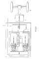
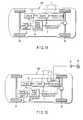
- the battery module B when power is supplied from a motor or dynamo 5 to the storage battery system, the battery module B is supplied with power from the motor/dynamo 5, and the battery module A supplies power lower than the first-mentioned one to the motor 5, as shown in FIG. 2.
- the supply of power to the battery module B is performed to efficiently accumulate braking energy therein.
- the level (W) of supplied power is varied. This is because the level of power supplied from the battery module A to the motor 5 during constant traveling is lower than that of power supplied to the battery module B during acceleration.
- the voltage Vmax is a maximum value within the range in which the battery module A is prevented from excessive charging.
- the battery module B has a characteristic suitable for CC or CV charging. Namely, the battery module B is charged with the particular current (CC charging), and reaches a voltage Ee when the charging is finished (SOC 100%).
- the final voltage Ee of the battery module B is, for example, 238V.
- the storage battery system 1 of the first embodiment comprises a booster mechanism 2, battery modules A and B connected to the booster mechanism 2, and a battery control unit (BMU) 4 connected to the battery modules A and B.
- the battery module B has a module, in which a plurality of single cells formed of thin nonaqueous electrolyte secondary batteries 7 are connected parallel to each other or in series.
- the battery module A is intermittently connected to the battery module B parallel to each other via a controller 8, and controls the amounts of current input to and output from the battery module B.
- the controller B contains a DC/DC converter, and performs constant voltage control to enable power to be supplied from the battery module A to the battery module B.
- the battery control unit (BMU) 4 comprises temperature sensors 61a and 61b for measuring the temperatures of the battery modules A and B, respectively, voltmeters 63a and 63b for measuring the voltages of the battery modules A and B, respectively, ammeters 62a and 62b for measuring the currents of the battery modules A and B, respectively, a charge/discharge control circuit 40, charge interruption circuit 41 and discharge interruption circuit 42.
- the temperature sensors 61 and 62 may be formed of thermo couples or thermistors.
- the charge/discharge control circuit 40 receives measurement signals from the temperature sensors 61a and 61b, voltmeters 63a and 63b and ammeters 62a and 62b. Based on the input signals the control circuit 40 computes the present charge capacity, and supplies signals to the charge interruption circuit 41 and discharge interruption circuit 42 for setting a certain state of charge (SOC), thereby controlling the charge/discharge of the nonaqueous electrolyte batteries 6 and 7 of the battery modules A and B.
- SOC state of charge
- the battery module B instantly discharges high power to the outside (during, for example, acceleration of the vehicle), and the SOC is suddenly reduced to 40% or less, the battery module A supplies power to the battery module B to set the SOC of the battery module B within the range of 40 to 60%. At this time, it is preferable that the supply of power is performed rapidly using constant-voltage control. More specifically, when the state of charge (SOC) of the battery module B drops to 40% or lower, the MBU 4 operates to have a power supply from the battery module A to the battery module B by the constant-voltage control.
- SOC state of charge
- the MBU 4 operates to have a power supply from the battery module A to the battery module B by the constant-voltage control.
- various types of external power sources can be connected to the battery module B to supply power thereto.
- the battery module B is provided with a power supply directly from an external power source. Further, the battery module A is provided with a power supply from the external power source via the battery module B.
- a negative electrode comprises a negative collector, and a negative-electrode layer provided on one or both sides of the collector and containing a negative-electrode active material, conductive agent and binding agent.
- each second nonaqueous electrolyte battery 7 of the battery module B a metal oxide, metal sulfide, metal nitride or metal alloy, which have an average grain size of primary particles of 1 ⁇ m or less and can occlude lithium ions within a range of 0.4V to 3V (vs.Li/Li+).
- a negative-electrode material containing a lithium titanium complex oxide As the lithium titanium complex oxide, lithium titanate (e.g., spinel-type Li 4+X Ti 5 O 12 , x: -1 ⁇ x ⁇ 3, and preferably, 0 ⁇ x ⁇ 1) can be used. In view of cycle life, lithium titanate is preferable. This is because the lithium occluding potential of lithium titanate is about 1.5V, and is electrochemically very stable material with respect to an aluminum foil collector or aluminum alloy foil collector.
- a ramsdellite-type lithium titanate such as Li 2+X Ti 3 O 7 (x: -1 ⁇ x ⁇ 3), can be used.
- the spinel-type lithium titanate and ramsdellite-type lithium titanate will be referred to as "lithium titanium oxides.”
- Lithium titanium complex oxides include, as well as lithium titanium oxides, titanium-based oxides that do not contain lithium.
- Lithium titanium oxides include, for example, a metal complex oxide containing at least one element selected from the group of TiO 2 , Ti, P, V, Sn, Cu, Ni and Fe.
- TiO 2 is of an anatase type and has low crystalline properties acquired at a thermal treatment temperature of 300 to 500°C.
- a metal complex oxide containing at least one element selected from the group of Ti, P, V, Sn, Cu, Ni and Fe, TiO 2 -P 2 O 5 , TiO 2 -V 2 O 5 , TiO 2 -P 2 O 5 -SnO 2 , and TiO 2 -P 2 O 5 -MeO (Me is at least one metal selected from the group consisting of Cu, Ni and Fe), etc., can be exemplified.
- the metal complex oxide has low crystalline properties, and has a microstructure in which a crystalline phase and amorphous phase are mixed, or only an amorphous phase exists. By virtue of this microstructure, the cycle performance can be significantly enhanced.
- a metal complex oxide containing a lithium titanium oxide and at least one element selected from the group of Ti, P, V, Sn, Cu, Ni and Fe is preferable.
- the negative-electrode active material may contain a material other than a lithium titanium complex oxide.
- This material is, for example, a carbonaceous material that can occlude and discharge lithium.
- the average grain size of the primary particles of the negative-electrode material is 1 ⁇ m or less.
- the use of a negative-electrode material with an average grain size of 1 ⁇ m or less enhances the cycle performance. In particular, this effect is conspicuous during rapid charging and high-output discharging. Concerning, for example, a negative-electrode for occluding and discharging lithium ions, the reason why the effect is conspicuous is that the finer, the grain size, the shorter the diffusion distances of lithium ions in the active material and the greater the specific surface of each particle. More preferably, the average grain size of the negative-electrode material is 0.3 ⁇ m or less.
- the average grain size of the negative-electrode material is small, aggregation of particles may easily occur, which may involve a reduction in the uniformity of the particle size of the negative-electrode active material. In light of this, it is desirable to set its lower limit to 0.001 ⁇ m.
- a negative-electrode active material with an average grain size of 1 ⁇ m or less
- a row material for the active material to synthesis to thereby prepare, as an active material precursor, powder with a diameter of 1 ⁇ m or less.
- the negative-electrode active material is acquired by crushing up the powder acquired after sintering into 1 ⁇ m or less, using a crusher, such as a ball mill or jet mill.
- the grain size of primary particles of the negative-electrode active material is measured by a laser-diffraction-type grain-size-distribution measuring apparatus (SALD-300 made by Shimazu Corporation).
- SALD-300 made by Shimazu Corporation.
- a aggregated sample is diffused in the following manner. That is, a sample of about 0.1g, an interfacial active material and distilled water of 1 - 2 mL are fed into a beaker and sufficiently agitated. After that, the resultant solution is injected into an agitation vessel, where it is subjected to light-intensity-distribution measurement performed 64 times at intervals of 2 seconds, thereby acquiring grain-size distribution data.
- measurement results such as a grain-size distribution and average grain size of the primary particles, are obtained.
- the negative collector is formed of aluminum foil or aluminum alloy foil. It is also preferable that the average crystal grain size of the aluminum foil or aluminum alloy foil is 50 ⁇ m or less, and more preferably, 10 ⁇ m or less. The smaller the average crystal grain size, the stronger the chemical and physical strengths. However, from the fact that a fine crystal structure is desirable to acquire excellent conductivity, it is desirable to set the lower limit of the average crystal grain size to 0.01 ⁇ m.
- the strength of the negative collector can be significantly increased.
- the greater the strength of the negative collector the greater the physical and chemical resistances of the collector, and hence the less the breakage of the collector.
- degradation of the collector due to dissolution/corrosion which is conspicuous in a long excessive-discharge cycle at a high temperature (40°C and above) can be suppressed to thereby suppress an increase in electrode resistance. Suppression in an increase in electrode resistance reduces the Joule heat, thereby suppressing heat generation by the electrodes.
- the negative collector when pressing the negative electrode, the smaller the average grain size of the negative-electrode active material, the greater the load on the negative collector. If the negative collector is formed of an aluminum foil or aluminum alloy foil with an average crystal grain size of 50 ⁇ m or less, it can wear a great pressing force exerted thereon by virtue of the strength of the negative-electrode material with an average grain size of 1 ⁇ m or less. As a result, breakage of the negative collector during pressing can be avoided.
- the thermal conductivity of the electrodes can be enhanced, and hence the heat-releasing property of the electrodes be enhanced. Furthermore, the synergistic effect of the suppression of the heat generation of the battery, and the enhancement of the heat-releasing property of the electrodes result in the suppression of increases in the temperature of the battery.
- Aluminum foil or aluminum alloy foil with an average crystal grain size of 50 ⁇ m or less is influenced in a complicated manner by many factors, such as their composition, impurities, process conditions, thermal treatment history, and heating and cooling conditions of annealing. Accordingly, during the manufacturing process, the crystal grain size of the negative collector is adjusted in light of all the above-mentioned factors.
- the negative collector may be produced using PACAL21 (product name) of Nippon Foil Mig. Co., Ltd.
- aluminum foil with the average crystal grain size of 50 ⁇ m or less can be produced by annealing aluminum foil with an average crystal grain size of 90 ⁇ m at 50 to 250°C, and cooling the resultant material to the room temperature.
- the average crystal grain size of aluminum and an aluminum alloy is measured as follows:
- Such average-crystal-grain-diameter computation is performed concerning five portions (5 viewing fields), and the average of the resultant values is set as an average crystal grain size.
- the expected error is about 5%.
- the thickness of the negative collector is 20 urn or less, and the purity of aluminum foil is 99.99% or more. It is also preferable that the aluminum alloy contains magnesium, tin, manganese, silicon, etc. In contrast, it is preferable that the amounts of transition metals, such as iron, copper, nickel and chrome, are set to 100 ppm or less.
- a carbon material such as acetylene black, carbon black, coke, carbon fiber or graphite, can be used as a conductive material.
- polytetrafluoroethylene PTFE
- PVdF polyvinylidene fluoride
- fluorine system rubber butadiene-styrene rubber, etc.
- the negative electrode is produced by, for example, suspending the negative-electrode active material, conductive agent and binding agent in an appropriate solvent, coating an aluminum foil or aluminum alloy foil collector with the suspended solids, drying them and pressing them.
- the thickness of an active-material layer on one side of the negative collector is preferably 5 to 100 ⁇ m, and more preferably, 5 to 50 ⁇ m. If the thickness of the active-material layer falls within the range of 5 to 50 ⁇ m, the layer exhibits high thermal conductivity during charging/discharging of a large current, and suppresses rapid heat generation.
- the negative-electrode active material of the first nonaqueous electrolyte battery 6 (battery module A) a material that occludes and discharges lithium ions with an average grain size of 1 ⁇ m or more.
- a lithium metal, lithium alloy or metal compound can be used as a material that occludes and discharges lithium ions with an average grain size of 1 ⁇ m or more.
- a lithium metal, lithium alloy or metal compound can be used. It is desirable to convert the negative-electrode active material of the average grain size of 1 ⁇ m or more into powder with a diameter of 1 ⁇ m or less as an active material precursor.
- the negative-electrode active material is acquired by crushing up the powder acquired after sintering into 1 ⁇ m or less, using a crusher, such as a ball mill or jet mill.
- the grain size of the negative-electrode active material is measured by a laser-diffraction-type grain-size-distribution measuring apparatus (SALD-300 made by Shimazu Corporation). Firstly, a sample of about 0.1g, an interfacial active material and distilled water of 1 - 2 mL are fed into a beaker and sufficiently agitated. After that, the resultant solution is injected into an agitation vessel, where it is subjected to light-intensity-distribution measurement performed 64 times at intervals of 2 seconds, thereby acquiring grain-size distribution data. Thus, measurement results, such as a grain-size distribution and average grain size, are obtained.
- SALD-300 laser-diffraction-type grain-size-distribution measuring apparatus
- the lithium alloy is, for example, a lithium aluminum alloy, lithium tin alloy, lithium magnesium alloy, lithium silicon alloy or lithium lead alloy.
- the carbon material that occludes and discharges lithium ions is, for example, natural graphite, artificial graphite, coke, vapor phase epoxy carbon fiber, meso-phase-pitch system carbon fiber, globular carbon, resin baked carbon. More preferably, the carbon material is natural graphite, artificial graphite, meso-phase-pitch system carbon fiber or globular carbon. Further, it is preferable that the face-to-face dimension d 002 of the faces (002) of the carbon material acquired by X-ray diffraction is 0.340 nm or less.
- the carbon material is a graphite material acquired using, as a raw material, natural graphite with a face-to-face dimension d 002 of 0.337 nm or less. It is preferable to shape the graphite material like scales or grains.
- the metal compound may be a metal oxide, metal sulfide or metal nitride, etc.
- the metal oxide is, for example, tungsten oxide (WO 3 ), amorphous tin oxide, tin silicon oxide (SnSiO 3 ) or silicon oxide (SiO), etc.
- the metal sulfide is, for example, a lithium sulfide (TiS 2 ), molybdenum sulfide (MoS 2 ), or ferric sulfide (FeS, FeS 2 , Li x FeS 2 )-
- the metal nitride is, for example, a lithium cobalt nitride (Li x Co y N, 0 ⁇ x ⁇ 4, 0 ⁇ y ⁇ 0.5). It is desirable that the negative collector be formed of copper foil.
- the negative collector has a thickness of 20 ⁇ m or less.
- a carbon material can be used as a conductive agent providing the negative electrode. This carbon material may be acetylene black, carbon black, coke, carbon fiber or graphite, etc.
- polytetrafluoroethylene PTFE
- PVdF polyvinylidene fluoride
- butadiene-styrene rubber etc.
- composition ratio of the negative-electrode active material, conductive agent and binding agent it is preferable to set the negative-electrode active material to 80 to 100 weight %, set the conductive agent to 3 to 18 weight %, and set the binding agent to 2 to 7 weight %.
- the negative electrode is produced by, for example, suspending the negative-electrode active material, conductive agent and binding agent in an appropriate solvent, coating an aluminum foil or aluminum alloy foil collector with the suspended solids, drying them and pressing them.
- the thickness of an active-material layer on one side of the negative collector is preferably 30 to 250 ⁇ m, and more preferably, 50 to 200 ⁇ m. If the thickness of the active-material layer falls within the range of 50 to 200 ⁇ m, high power can be acquired during low-load discharging.
- a positive electrode comprises a positive collector, and a positive-electrode layer provided on one or both sides of the collector and containing a positive-electrode active material, conductive agent and binding agent.
- the positive collector may be formed of aluminum foil or aluminum alloy foil, and preferably, has an average crystal grain size of 50 ⁇ m or less, like the negative collector. More preferably, the average crystal grain size of the positive collector is 10 ⁇ m or less.
- the strength of the aluminum foil or aluminum alloy foil can be significantly enhanced, which enables the positive electrode to be pressed by high pressure, thereby enhancing the capacity density of the positive electrode.
- the smaller the average crystal grain size the smaller the number of occurrences of pinholes and cracks, and the stronger the chemical and physical strengths of the positive collector.
- the thickness of the positive collector is preferably 20 ⁇ m or less.
- the active material of the positive electrode is, for example, an oxide, sulfide or polymer, etc.
- the oxide is, for example, a manganese dioxide such as MnO 2 , ferric oxide, a copper oxide, a nickel oxide, a lithium manganese complex oxide such as Li x Mn 2 O 4 or Li x MnO 2 , a lithium nickel complex oxide such as Li x NiO 2 , a lithium cobalt complex oxide such as Li x CoO 2 , a lithium nickel cobalt complex oxide such as LiNi 1-y Co y O 2 , a lithium manganese cobalt complex oxide such as LiMn y Co 1-y O 2 , a spinel-type lithium manganese nickel complex oxide such as LiMn 2-y Ni y O 4 , a lithium phosphor oxide of an olivine structure such as Li x FePO 4 , Li x Fe 1-y PO 4 , Li x FeMn y PO 4 , Li x CoPO 4 ,
- the polymer may be a conductive polymer material such as polyaniline or polypyrol, or a disulfide-based polymer material. Sulfur (S) or a carbon fluoride, etc., can also be used.
- the positive-electrode active material is, for example, a lithium manganese complex oxide, lithium nickel complex oxide, lithium cobalt complex oxide, lithium nickel cobalt complex oxide, spinel-type lithium manganese nickel complex oxide, lithium manganese cobalt complex oxide, or lithium iron phosphate.
- the lithium manganese complex oxide, lithium nickel complex oxide, lithium cobalt complex oxide, lithium nickel cobalt complex oxide and lithium manganese cobalt complex oxide can suppress reaction of the positive-electrode and negative-electrode active materials and nonaqueous electrolyte at high temperature, thereby significantly increasing the life of the battery.
- the use of the lithium nickel cobalt manganese complex oxide enables a high battery voltage to be acquired.
- the more preferable ranges concerning the mole ratio between a, b, c and d are 0 ⁇ a ⁇ 1.1, 0.1 ⁇ b ⁇ 0.5, 0 ⁇ c ⁇ 0.9 and 0.1 ⁇ d ⁇ 0.5.
- the conductive agent is, for example, acetylene black, carbon black or graphite.
- the binding agent is, for example, polytetrafluoroethylene (PTFE), polyvinylidene fluoride (PVdF), butadiene-styrene rubber, etc.
- composition ratio of the negative-electrode active material, conductive agent and binding agent it is preferable to set the negative-electrode active material to 80 to 95 weight %, set the conductive agent to 3 to 18 weight %, and set the binding agent to 2 to 7 weight %.
- the positive electrode is produced by, for example, suspending the negative-electrode active material, conductive agent and binding agent in an appropriate solvent, coating an aluminum foil or aluminum alloy foil collector with the suspended solids, drying them and pressing them.
- the thickness of an active-material layer on one side of the positive collector is preferably 5 to 250 ⁇ m, and more preferably, 5 to 200 ⁇ m. If the thickness of the active-material layer falls within the range of 5 to 200 ⁇ m, the layer exhibits high thermal conductivity during charging/discharging of a large current, and suppresses rapid heat generation.
- separator synthetic resin nonwoven fabric, a polyethylene porous film or a polypropylene porous film, etc., can be used.
- the nonaqueous electrolyte is, for example, a liquid nonaqueous electrolyte prepared by dissolving an electrolyte by an organic solvent, a gelled nonaqueous electrolyte acquired by combining the liquid nonaqueous electrolyte and a polymer material, or a solid nonaqueous electrolyte acquired by combining lithium salt and a polymer material. Further, a room-temperature molten salt (ionic melt) containing lithium ions may be used as the nonaqueous electrolyte.
- a room-temperature molten salt (ionic melt) containing lithium ions may be used as the nonaqueous electrolyte.
- the liquid nonaqueous electrolyte is, for example, LiClO 4 , LiPF 6 , LiBF 4 , LiAsF 6 , LiCF 3 SO 3 , LiN(CF 3 SO 2 ) 2 , Lin(C 2 F 5 SPO 2 ) 2 , Li(CF 3 SO 2 ) 3 C or LiB[(OCO) 2 ] 2 , etc.
- One or more types of electrolytes can be used.
- the organic solvent is, for example, a cyclic carbonate such as propylene carbonate (PC) or ethylene carbonate (EC), an open-chain carbonate such as diethyl carbonate (DEC), dimethyl carbonate (DMC) or methylethyl carbonate, an open-chain ether such as dimethoxyethane (DME) or diethoxyethane (DEE), a cyclic ether such as tetrahydrofuran (THF) or dioxolane (DOX), or a single or mixed solvent such as ⁇ -butyrolactone (GBL), acetonitrile (AN) or sulfolane (SL).
- a cyclic carbonate such as propylene carbonate (PC) or ethylene carbonate (EC)
- an open-chain carbonate such as diethyl carbonate (DEC), dimethyl carbonate (DMC) or methylethyl carbonate
- an open-chain ether such as dimethoxyethane (DME
- a nonaqueous electrolyte containing GBL is used, the amount of gas occurring during charging can be reduced. It is more preferable if a nonaqueous electrolyte containing, as well as GBL, at least one selected from the group consisting of PC and EC.
- PVdF polyvinylidene fluoride
- PAN polyacrylonitrile
- PEO polyethylene oxide
- the room-temperature molten salt (ionic melt) is formed of lithium ions, organic cation and organic anion.
- the molten salt is kept liquid at 100°C or less, and more preferably, at room temperature or less.
- a metal container can also be used as well as the laminate-film container 17 shown in FIG. 3.
- the container may be shaped flat, rectangular, cylindrical, laminated, or like a coin or button or sheet.
- the size of the container may be, for example, that of a large battery installed in an electric motor car, etc.
- a multi-layer film including a metal layer and a resin layer coating the metal layer may be used, for example.
- the resin layer is used to reinforce the metal layer and may be formed of a polymer, such as polypropylene (PP), polyethylene (PE), nylon or polyethylene terephthalate (PET).
- the laminate-film container can be acquired by, for example, attaching laminate films to each other by thermal fusion bonding.
- the thickness of the laminate film it is preferable to set the thickness of the laminate film to 0.5 mm or less. It is also preferable to set, to 0.01 mm, the lower limit of the thickness of the laminate film.
- the metal container of aluminum or an aluminum alloy. It is also preferable to set the average crystal grain size to 50 ⁇ m or less. If the average crystal grain size is set to 50 ⁇ m or less, the strength of the aluminum or aluminum alloy container is increased. Therefore, in this case, even if the metal container is formed thin, it can have sufficient mechanical strength. If the metal container is formed thin, the heat-releasing property of the container is enhanced, thereby suppressing an increase in the temperature of the battery. Further, the energy density is also enhanced, which enables the battery to be made lighter and smaller. It is more preferable to set the average crystal grain size to 10 ⁇ m or less. The smaller the average crystal grain size, the stronger the chemical and physical strengths. However, from the fact that a fine crystal structure is desirable to acquire excellent conductivity, it is desirable to set the lower limit of the average crystal grain size to 0.01 ⁇ m.
- the thickness of the metal container is 0.5 mm or less, and also to set the lower limit of the thickness to 0.05 mm.
- the purity of the above-mentioned aluminum foil is desirably 99.99% or more. It is preferable to use, as the above-described aluminum alloy, an aluminum alloy containing elements such as magnesium, zinc and silicon. It is preferable that the amounts of transition metals, such as iron, copper, nickel and chrome, are set to 100 ppm or less.
- the metal container can be sealed using a laser. Therefore, the volume of the sealing portion can be reduced compared to a laminate-film container, and hence the energy density can be enhanced.
- the storage battery system of the first embodiment is suitable for rapid charging and discharging, as well as for charging using regenerative power.
- Examples of this use are a power supply for digital cameras, a power supply for light vehicles such as assist bicycles, a backup power supply (uninterruptible power supply devices) for personal computers or for use in factories, and a cleaner.
- a storage battery system can be made to the same structure as that of the system of the first embodiment, except for regenerative power is not used for charging. It is preferable to set the charging rate to a range of 2C or more and 120C or less.
- “1C” is a current required for each unit cell to be completely discharged within an hour. For convenience, the nominal capacitance of each unit cell can be replaced with 1C.
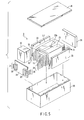
- FIG. 5 is an exploded perspective view of the battery pack used in the storage battery system of the second embodiment.
- FIG. 6 is a block diagram illustrating the circuit diagram of the battery pack of FIG. 5.
- Each single battery 21 included in the battery pack of FIG. 5 is formed of the flat nonaqueous electrolyte battery shown in FIG. 3.
- a plurality of single batteries 21 are stacked on each other in the thickness direction of the battery, with positive and negative terminals 15 and 16 protruded in the same direction.
- the single batteries 21 are connected in series, thereby providing the battery modules 6 and 7.
- the battery modules 6 and 7 are formed integral by an adhesive tape 23 as shown in FIG. 5.
- the rated capacity of each single battery 21 is, desirably, 2 Ah or more and 100 Ah or less, and more preferably, to 3 Ah or more and 40 Ah or less.
- the rated capacity means the capacity acquired when discharge is executed at a rate of 0.2C.
- the number of single batteries 21 it is preferable to set the number of single batteries 21 to 5 or more and 500 or less, and more preferably, to 5 or more and 200 or less. Further, in on-vehicle power supply systems, to acquire high voltage, it is desirable to connect the single batteries 21 in series.
- a printed circuit board 24 is provided at the side of the battery from which the positive and negative terminals 15 and 16 protrude.
- the printed circuit board 24 mounts thereon a thermistor meter section 25a, a protection circuit 26 and a terminal 27 to be connected to an external device, shown in FIG. 6.
- Thermistor measuring sections 25b may be provided for arbitrary ones of the single batteries 21. Alternatively, thermistor measuring sections 25b may be provided for all single batteries 21. When a certain number of thermistor measuring sections 25b are provided for arbitrary single batteries 21, at least one thermistor measuring section 25b must be provided for the single battery 21 located at the vertical center of the battery modules 6 and 7 stacked vertically. Further, the highest temperature detected is set as the temperature of the battery modules 6 and 7, regardless of whether thermistor measuring sections 25b are provided for arbitrary unit cells 21 or all single batteries 21. Furthermore, it is desirable to locate the thermistor measuring section 25b on the center of the flat surface of the single battery 21.
- the measurement result of the thermistor is sent as a detected signal to the protection circuit 26.
- the positive-side lines 28 of the battery modules 6 and 7 are electrically connected to the positive-side connector 29 of the protection circuit 26 of the printed circuit board 24.
- the negative-side lines 30 of the battery modules 6 and 7 are electrically connected to the negative-side connector 31 of the protection circuit 26 of the printed circuit board 24.
- the protection circuit 26 comprises a charge/discharge control circuit 40, charge interruption circuit 41, discharge interruption circuit 42, voltmeters 63a and 63b and ammeters 62a and 62b (see FIG. 4).
- a line 32 for detecting the voltage and current of each single battery 21 is connected thereto, and a signal acquired through the line 32 is sent to the protection circuit 26.
- the terminal 27 is connected to a charger and external load.
- the protection circuit 26 serves not only as a battery control unit, but also as a unit for disconnecting, from each other, a plus-side line 31a and minus-side line 31b between the circuit 26 and terminal 27 under a preset condition, to thereby secure safety.
- the preset condition is, for example, "when the detected temperature reaches a preset value", or "when excessive charging, discharging or current of each single battery 21 is detected”.
- This detection method is executed concerning each single battery 21 or the entire single batteries 21. When detection is executed on each single battery 21, its voltage may be detected, or its positive or negative potential may be detected. In the latter case, a lithium electrode as a reference electrode is interposed between each pair of adjacent ones of the single batteries 21.
- protection sheets 33 made of rubber or resin.
- a protection block 34 made of rubber or resin is interposed between the printed circuit board 24 and the side of the battery modules 6 and 7, from which the positive and negative terminals 15 and 16 protrude.
- the battery modules 6 and 7 are contained in a container 35 along with the protection sheets 33, protection block 34 and printed circuit board 24.
- the protection sheets 33 are located on the inner surfaces of the long sides of the container 35 and on the inner surface of one short side of the container 35, while the printed circuit board 24 is located on the inner surface of the other short side of the container 35.
- the battery modules 6 and 7 are located in the space defined by the protection sheets 33 and printed circuit board 24.
- a lid 36 is attached to close the upper opening of the container 35.
- the battery modules 6 and 7 may be fixed using a thermally contractive tape, instead of the adhesive tapes 23.
- protective sheets are provided on opposite sides of the battery modules, and a thermally contractive tube is wound on the resultant structure. After that, the thermally contractive tube is thermally contracted to fix the battery modules.
- the single batteries 21 shown in FIGS. 5 and 6 are connected in series, they may be connected parallel to each other to increase the battery capacity. It is a matter of course that the unit cells may be connected in series or parallel after they are assembled into a battery pack.
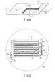
- FIG. 8 is a perspective view partly broken, illustrating a flat nonaqueous electrolyte second battery for use in the battery pack of FIG. 5, and
- FIG. 9 is an enlarged sectional view of the IX portion of FIG. 8.
- the laminate-film container 17 contains a laminated electrode group 18.
- the laminated electrode group 18 has a laminated structure in which positive electrodes 12 and negative electrodes 13 are alternately stacked on each other, with a corresponding separator 14 interposed between each pair of adjacent ones of the electrodes 12 and 13.
- Each of the positive electrodes 12 includes a positive collector 12a, and layers 12b containing a positive-electrode active material and provided on the opposite surfaces of the positive collector 12a.
- Each of the negative electrodes 13 includes a negative collector 13a, and layers 13b containing a negative-electrode active material and provided on the opposite surfaces of the negative collector 13a.
- Each of the negative collectors 13a of the negative electrodes 13 has one end extended outward of the positive electrodes 12.
- the negative collectors 13a extended outward of the positive electrodes 12 is electrically connected to a band-shaped negative terminal 16.
- the distal end of the band-shaped negative terminal 16 is extended to the outside of the container 17.
- each of the positive collectors 12a of the positive electrodes 12 has one end (not shown) extended outward of the negative electrodes 13 at the opposite side of the extended end of each negative collector 13a.
- the positive collectors 12a extended outward of the negative electrodes 13 are electrically connected to a band-like positive terminal 15.
- the distal end of the band-like positive terminal 15 is positioned at the opposite side of the negative terminal 16, and extended outward of the container 17.
- Lithium titanate (Li 4 Ti 5 O 12 ) with an average grain size of 0.3 ⁇ m, as an active material, carbon powder with an average grain size of 0.4 ⁇ m, as a conductive agent, and polyvinylidene fluoride (PVdF) as a binding agent were mixed with a weight ratio of 90:7:3 in n-methylpyrrolidone (NMP) solvent, thereby preparing slurry.
- NMP n-methylpyrrolidone
- the slurry was coated on aluminum alloy foil (purity: 99.4%) with a thickness of 12 ⁇ m and an average crystal grain size of 50 ⁇ m, and the resultant structure was dried and pressed to thereby prepare a negative electrode with an electrode density of 2.4 g/cm 3 .
- the negative collector was prepared by annealing, at 200°C, aluminum alloy foil (purity: 99.4%) with a thickness of 12 ⁇ m and an average crystal grain size of 90 ⁇ m, and then cooling the resultant structure to room temperature.
- Lithium cobalt oxide (LiCoO 2 ) with an average grain size of 3 ⁇ m, as an active material, graphite powder as a conductive agent, and polyvinylidene fluoride (PVdF) as a binding agent were mixed with a weight ratio of 87:8:5 in n-methylpyrrolidone (NMP) solvent, thereby preparing slurry.
- the slurry was coated on aluminum foil (purity: 99.99%) with a thickness of 15 ⁇ m and an average crystal grain size of 12 ⁇ m, and the resultant structure was dried and pressed to thereby prepare a positive electrode with an electrode density of 3.5 g/cm 3 .
- the positive collector was prepared by annealing, at 140°C, aluminum foil (purity: 99.99%) with a thickness of 15 ⁇ m and an average crystal grain size of 90 ⁇ m, and then cooling the resultant structure to room temperature.
- a laminate film containing aluminum and having a thickness of 0.1 mm was used as the material of the container.
- the aluminum layer included in the laminate film containing aluminum had a thickness of about 0.03 mm, and had an average crystal grain size of about 100 ⁇ m.
- Polypropylene was used as a resin for reinforcing the aluminum layer.
- the container was prepared by sealing the laminate film utilizing thermal fusion bonding.
- a band-like positive terminal was electrically connected to the positive electrode
- a band-like negative terminal was electrically connected to the negative electrode.
- a separator formed of a polyethylene porous film with a thickness of 12 ⁇ m was tightly attached to the positive electrode to cover it.
- the negative electrode was superposed upon the positive electrode covered with the separator.
- a plurality of electrodes thus prepared were wound spirally into an electrode group. The electrode group was pressed flat and inserted in the container.
- a lithium salt LiBF 4
- an organic solvent containing EC and GBL with a volume ratio of 1:2 (EC:GBL) to prepare a liquid nonaqueous electrolyte.
- the resultant nonaqueous electrolyte was injected into the container, whereby a nonaqueous electrolyte battery 7 with a thickness of 6.5 mm, a width of 70 mm and a height of 100 mm, which had the above-described structure shown in FIG. 2, was acquired.
- the weight of the battery was 90g and its nominal capacity was 3000 mAh.
- nonaqueous electrolyte batteries 7 similar to the above were prepared and connected in series on a plastic plate, thereby forming one module. 17 modules similar to this were prepared and connected in series, thereby producing a battery module B incorporated in a storage battery system (rated voltage: 200V; rated capacity: 3 Ah).
- Natural graphite powder with an average grain size of 10 ⁇ m, as an active material, and polyvinylidene fluoride (PVdF) as a binding agent were mixed with a weight ratio of 95:5 in n-methylpyrrolidone (NMP) solvent, thereby preparing slurry.
- the slurry was coated on copper foil (purity: 99.9%) with a thickness of 12 ⁇ m, and the resultant structure was dried and pressed to thereby prepare a negative electrode with an electrode density of 1.3 g/cm 3 (the thickness of the negative-electrode active material: 150 ⁇ m).
- Lithium cobalt oxide (LiCoO 2 ) with an average grain size of 3 ⁇ m, as an active material, graphite powder as a conductive agent, and polyvinylidene fluoride (PVdF) as a binding agent were mixed with a weight ratio of 87:8:5 in n-methylpyrrolidone (NMP) solvent, thereby preparing slurry.
- the slurry was coated on aluminum foil (purity: 99.99%) with a thickness of 15 ⁇ m and an average crystal grain size of 12 ⁇ m, and the resultant structure was dried and pressed to thereby prepare a positive electrode with an electrode density of 3.5 g/cm 3 .
- the positive collector was prepared by annealing, at 140°C, aluminum foil (purity: 99.99%) with a thickness of 15 ⁇ m and an average crystal grain size of 90 ⁇ m, and then cooling the resultant structure to room temperature.
- a laminate film containing aluminum and having a thickness of 0.1 mm was used as the material of the container.
- the aluminum layer included in the laminate film containing aluminum had a thickness of about 0.03 mm, and had an average crystal grain size of about 100 ⁇ m.
- Polypropylene was used as a resin for reinforcing the aluminum layer.
- the container was prepared by sealing the laminate film utilizing thermal fusion bonding.
- a band-like positive terminal was electrically connected to the positive electrode
- a band-like negative terminal was electrically connected to the negative electrode.
- a separator formed of a polyethylene porous film with a thickness of 12 ⁇ m was tightly attached to the positive electrode to cover it.
- the negative electrode was superposed upon the positive electrode covered with the separator.
- a plurality of electrodes thus prepared were wound spirally into an electrode group. The electrode group was pressed flat and inserted in the container.
- a lithium salt LiBF 4
- an organic solvent containing EC and GBL with a volume ratio of 1:2 (EC:GBL) to prepare a liquid nonaqueous electrolyte.
- the resultant nonaqueous electrolyte was injected into the container, whereby a nonaqueous electrolyte battery A with a thickness of 13 mm, a width of 70 mm and a height of 150 mm, which had the above-described structure shown in FIG. 2, was acquired.
- the weight of the battery was 400g and its nominal capacity was 12 Ah.
- nonaqueous electrolyte batteries 6 similar to the above were prepared and connected in series on a plastic plate, thereby forming one module. Twenty modules similar to this were prepared and connected in series, thereby producing a battery module A incorporated in a storage battery system (rated voltage: 211V; rated capacity: 15 Ah).
- BMU battery control unit 4 and booster mechanism 2
- the above-described storage battery system and on-vehicle power supply system shown in FIGS. 1 and 2 were prepared.
- a storage test was executed, in which power was supplied from the battery module A to the battery module B two times per one day, with the SOC levels of the battery modules A and B set at 90% and 10%, respectively, and the motor/dynamo stopped for 180 days at the temperature of 45°C.
- changes in the resistance of the battery module B were measured.
- example 2 the same storage battery system and on-vehicle power supply system as in example 1 were used.
- a storage test was executed, in which power was supplied from the battery module A to the battery module B once per 30 days, with the SOC levels of the battery modules A and B set at 90% and 90%, respectively, and the motor/dynamo stopped for 180 days at the temperature of 45°C.
- changes in the resistance of the battery module B were measured.
- the same storage battery system and on-vehicle power supply system as in example 1 were used.
- a storage test was executed, in which power was supplied from the battery module A to the battery module B once per 30 days, with the SOC levels of the battery modules A and B set at 90% and 80%, respectively, and the motor/dynamo stopped for 180 days at the temperature of 45°C.
- changes in the resistance of the battery module B were measured.
- the same storage battery system and on-vehicle power supply system as in example 1 were used.
- a storage test was executed, in which no power was supplied from the battery module A to the battery module B, with the SOC levels of the battery modules A and B set at 90% and 10%, respectively, and the motor/dynamo stopped for 180 days at the temperature of 45°C. Also in this test, changes in the resistance of the battery module B were measured.
- the same storage battery system and on-vehicle power supply system as in example 1 were used.
Landscapes
- Engineering & Computer Science (AREA)
- Transportation (AREA)
- Mechanical Engineering (AREA)
- Chemical & Material Sciences (AREA)
- Power Engineering (AREA)
- General Chemical & Material Sciences (AREA)
- Sustainable Development (AREA)
- Sustainable Energy (AREA)
- Chemical Kinetics & Catalysis (AREA)
- Electrochemistry (AREA)
- Life Sciences & Earth Sciences (AREA)
- Combustion & Propulsion (AREA)
- Manufacturing & Machinery (AREA)
- Materials Engineering (AREA)
- Automation & Control Theory (AREA)
- Secondary Cells (AREA)
- Battery Mounting, Suspending (AREA)
- Battery Electrode And Active Subsutance (AREA)
- Charge And Discharge Circuits For Batteries Or The Like (AREA)
- Control Of Charge By Means Of Generators (AREA)
Applications Claiming Priority (1)
| Application Number | Priority Date | Filing Date | Title |
|---|---|---|---|
| JP2006163668A JP4413888B2 (ja) | 2006-06-13 | 2006-06-13 | 蓄電池システム、車載電源システム、車両、および蓄電池システムの充電方法 |
Publications (3)
| Publication Number | Publication Date |
|---|---|
| EP1921705A2 true EP1921705A2 (fr) | 2008-05-14 |
| EP1921705A3 EP1921705A3 (fr) | 2010-04-07 |
| EP1921705B1 EP1921705B1 (fr) | 2013-02-13 |
Family
ID=38461023
Family Applications (1)
| Application Number | Title | Priority Date | Filing Date |
|---|---|---|---|
| EP07251183A Ceased EP1921705B1 (fr) | 2006-06-13 | 2007-03-20 | Système de stockage de batterie, système d'alimentation électrique pour véhicule, véhicule et procédé de chargement d'un système de stockage de batterie |
Country Status (4)
| Country | Link |
|---|---|
| US (1) | US8047316B2 (fr) |
| EP (1) | EP1921705B1 (fr) |
| JP (1) | JP4413888B2 (fr) |
| CN (1) | CN100544107C (fr) |
Cited By (8)
| Publication number | Priority date | Publication date | Assignee | Title |
|---|---|---|---|---|
| WO2010033076A1 (fr) * | 2008-09-17 | 2010-03-25 | Stl Energy Technology (S) Pte Ltd | Système et procédé d’essai de rodage fonctionnel de bloc-piles |
| EP2076929A4 (fr) * | 2006-10-16 | 2010-08-25 | Lg Chemical Ltd | Système de batterie auxiliaire haute puissance comprenant des éléments chargés asymétriques |
| US8846224B2 (en) | 2006-10-16 | 2014-09-30 | Lg Chem, Ltd. | High power secondary battery system comprising asymmetric charged cells |
| WO2015103173A1 (fr) * | 2014-01-02 | 2015-07-09 | Johnson Controls Technology Company | Module de batterie micro-hybride pour un véhicule |
| US9461307B2 (en) | 2006-09-15 | 2016-10-04 | Kabushiki Kaisha Toshiba | Power supply system and motor car |
| RU2677635C2 (ru) * | 2015-12-04 | 2019-01-18 | Российская Федерация, от имени которой выступает Министерство обороны Российской Федерации | Способ эксплуатации литий-ионной аккумуляторной батареи в автономной системе электропитания искусственного спутника земли |
| CN109565045A (zh) * | 2016-07-13 | 2019-04-02 | 株式会社杰士汤浅国际 | 锂二次电池用正极活性物质、其制造方法和锂二次电池 |
| WO2019201359A1 (fr) * | 2018-04-17 | 2019-10-24 | Pme Technology Sas | Système et procédé de conversion d'énergie électrique |
Families Citing this family (141)
| Publication number | Priority date | Publication date | Assignee | Title |
|---|---|---|---|---|
| US7927742B2 (en) | 2004-10-29 | 2011-04-19 | Medtronic, Inc. | Negative-limited lithium-ion battery |
| US7582387B2 (en) | 2004-10-29 | 2009-09-01 | Medtronic, Inc. | Lithium-ion battery |
| US7662509B2 (en) | 2004-10-29 | 2010-02-16 | Medtronic, Inc. | Lithium-ion battery |
| US7563541B2 (en) | 2004-10-29 | 2009-07-21 | Medtronic, Inc. | Lithium-ion battery |
| US7337010B2 (en) | 2004-10-29 | 2008-02-26 | Medtronic, Inc. | Medical device having lithium-ion battery |
| US9065145B2 (en) | 2004-10-29 | 2015-06-23 | Medtronic, Inc. | Lithium-ion battery |
| US8980453B2 (en) | 2008-04-30 | 2015-03-17 | Medtronic, Inc. | Formation process for lithium-ion batteries |
| KR101326118B1 (ko) | 2004-10-29 | 2013-11-06 | 메드트로닉 인코포레이티드 | 리튬 이온 전지의 충전방법 |
| US7641992B2 (en) | 2004-10-29 | 2010-01-05 | Medtronic, Inc. | Medical device having lithium-ion battery |
| US8105714B2 (en) | 2004-10-29 | 2012-01-31 | Medtronic, Inc. | Lithium-ion battery |
| US9077022B2 (en) | 2004-10-29 | 2015-07-07 | Medtronic, Inc. | Lithium-ion battery |
| CN101048898B (zh) | 2004-10-29 | 2012-02-01 | 麦德托尼克公司 | 锂离子电池及医疗装置 |
| US7682745B2 (en) | 2004-10-29 | 2010-03-23 | Medtronic, Inc. | Medical device having lithium-ion battery |
| JP4839722B2 (ja) * | 2005-08-08 | 2011-12-21 | トヨタ自動車株式会社 | 車両の電源装置 |
| DE102007010738B4 (de) * | 2007-02-27 | 2012-01-26 | Daimler Ag | Leiterplattenschutz für eine Batterie und Verwendung der Batterie |
| US20080218127A1 (en) * | 2007-03-07 | 2008-09-11 | O2Micro Inc. | Battery management systems with controllable adapter output |
| US8222870B2 (en) * | 2007-03-07 | 2012-07-17 | O2Micro, Inc | Battery management systems with adjustable charging current |
| JP4714229B2 (ja) * | 2008-02-22 | 2011-06-29 | 株式会社日立製作所 | リチウム二次電池 |
| JP2009259798A (ja) * | 2008-03-19 | 2009-11-05 | Panasonic Corp | 非水電解質二次電池 |
| JP2009277395A (ja) * | 2008-05-13 | 2009-11-26 | Hitachi Maxell Ltd | 非水二次電池および非水二次電池システム |
| US8076797B2 (en) * | 2008-05-15 | 2011-12-13 | Indy Power Systems Llc | Energy transfer circuit and method |
| CN102386637B (zh) * | 2010-09-03 | 2013-11-13 | 凹凸电子(武汉)有限公司 | 电池管理系统及控制车的方法 |
| US8111038B2 (en) * | 2008-06-12 | 2012-02-07 | O2 Micro, Inc | Vehicle electronic systems with battery management functions |
| EP2307218B1 (fr) * | 2008-06-27 | 2015-09-30 | Proterra Inc. | Systèmes de batterie de véhicule et procédés associés |
| US8294286B2 (en) * | 2008-07-15 | 2012-10-23 | F3 & I2, Llc | Network of energy generating modules for transfer of energy outputs |
| US7619319B1 (en) * | 2008-07-15 | 2009-11-17 | F3 & I2, Llc | Network of energy generating modules for transfer of energy outputs |
| JP5339407B2 (ja) * | 2008-07-16 | 2013-11-13 | Necエナジーデバイス株式会社 | 電池パック |
| WO2010008058A1 (fr) * | 2008-07-17 | 2010-01-21 | 旭硝子株式会社 | Composite d'anode pour pile à électrolyte non aqueux |
| JP5018681B2 (ja) * | 2008-08-01 | 2012-09-05 | トヨタ自動車株式会社 | リチウムイオン二次電池の制御方法、及び、リチウムイオン二次電池システム |
| US7608934B1 (en) * | 2008-08-14 | 2009-10-27 | F3 & I2, Llc | Power packaging with railcars |
| US8294285B2 (en) | 2008-08-14 | 2012-10-23 | F3 & I2, Llc | Power packaging with railcars |
| JP4466772B2 (ja) * | 2008-09-03 | 2010-05-26 | トヨタ自動車株式会社 | 車両の制御装置 |
| JP5372449B2 (ja) | 2008-09-24 | 2013-12-18 | 三洋電機株式会社 | バッテリシステム |
| US20100178556A1 (en) * | 2009-01-15 | 2010-07-15 | Veselin Manev | Negative electrode for lithium ion battery |
| US8453770B2 (en) | 2009-01-29 | 2013-06-04 | Tesla Motors, Inc. | Dual motor drive and control system for an electric vehicle |
| US20100187024A1 (en) * | 2009-01-29 | 2010-07-29 | Tesla Motors, Inc. | All wheel drive electric vehicle power assist drive system |
| DE202009005662U1 (de) * | 2009-04-17 | 2009-07-09 | Finkbeiner, Gerhard, Dipl.-Ing. | Hebevorrichtung zum Anheben von Lasten, insbesondere Fahrzeugen |
| US20100294579A1 (en) * | 2009-05-25 | 2010-11-25 | Chen Fei-Neng | Auto-charging power device and electric vehicle with auto-charging power device |
| US8304929B2 (en) * | 2009-06-18 | 2012-11-06 | Lear Corporation | Inverter with network interface |
| WO2010101307A2 (fr) * | 2009-06-25 | 2010-09-10 | 日本碍子株式会社 | Matière active d'électrode positive et batterie secondaire au lithium utilisant une telle matière |
| US8307930B2 (en) * | 2009-07-20 | 2012-11-13 | International Truck Intellectual Property Company, Llc | Scalable, hybrid energy storage for plug-in vehicles |
| DE102009034674A1 (de) | 2009-07-24 | 2011-01-27 | Li-Tec Battery Gmbh | Lithium-Ionen-Batterie |
| US20110037439A1 (en) * | 2009-08-17 | 2011-02-17 | Apple Inc. | Increasing energy density in rechargeable lithium battery cells |
| DE102009054078A1 (de) * | 2009-11-20 | 2011-05-26 | Li-Tec Battery Gmbh | Batterieproduktionseinrichtung |
| JP2011114333A (ja) * | 2009-11-24 | 2011-06-09 | Goro Igarashi | 多用途利用の蓄電器 |
| KR101224496B1 (ko) * | 2010-02-04 | 2013-01-21 | 주식회사 엘지화학 | 보강부재를 포함하고 있는 전지팩 |
| CN102823209B (zh) | 2010-04-09 | 2015-06-10 | 丰田自动车株式会社 | 通信装置、通信系统以及车辆 |
| US8768533B2 (en) * | 2010-04-09 | 2014-07-01 | Toyota Jidosha Kabushiki Kaisha | Vehicle, communication system, and communication device |
| US9365128B2 (en) | 2010-04-26 | 2016-06-14 | Proterra Inc. | Systems and methods for automatic connection and charging of an electric vehicle at a charging station |
| JP6087489B2 (ja) * | 2010-08-20 | 2017-03-01 | 株式会社東芝 | 組電池システム |
| TWI404644B (zh) * | 2010-09-16 | 2013-08-11 | O2Micro Int Ltd | 電池管理系統及控制車的方法 |
| US8981710B2 (en) | 2010-09-20 | 2015-03-17 | Indy Power Systems Llc | Energy management system |
| US9176194B2 (en) * | 2010-10-08 | 2015-11-03 | GM Global Technology Operations LLC | Temperature compensation for magnetic determination method for the state of charge of a battery |
| US9209451B2 (en) * | 2010-12-24 | 2015-12-08 | Kyocera Corporation | Lithium rechargeable battery comprising a lithium titanate sintered body |
| JP5344047B2 (ja) * | 2011-02-03 | 2013-11-20 | トヨタ自動車株式会社 | 二次電池の出力制御装置 |
| WO2012128252A1 (fr) * | 2011-03-18 | 2012-09-27 | 三洋電機株式会社 | Système de stockage d'énergie |
| JP2014519797A (ja) * | 2011-05-19 | 2014-08-14 | リ−テック・バッテリー・ゲーエムベーハー | バッテリー製造装置およびバッテリー製造装置を制御するための方法 |
| JP5509152B2 (ja) * | 2011-05-31 | 2014-06-04 | 株式会社日立製作所 | 蓄電システム |
| US9287580B2 (en) | 2011-07-27 | 2016-03-15 | Medtronic, Inc. | Battery with auxiliary electrode |
| WO2013030882A1 (fr) | 2011-08-30 | 2013-03-07 | トヨタ自動車株式会社 | Véhicule |
| KR101281066B1 (ko) * | 2011-10-18 | 2013-07-09 | 송영길 | 전기자동차용 하이브리드 배터리 시스템 |
| WO2013082629A1 (fr) * | 2011-12-02 | 2013-06-06 | Karim Nadeem | Système de batterie à double chimie pour utilisation dans des véhicules électriques à branchement ou hybrides |
| US20130149560A1 (en) | 2011-12-09 | 2013-06-13 | Medtronic, Inc. | Auxiliary electrode for lithium-ion battery |
| JP2013131395A (ja) * | 2011-12-21 | 2013-07-04 | Sony Corp | 二次電池、電池パック、電動車両、電力貯蔵システム、電動工具および電子機器 |
| CN202435073U (zh) * | 2011-12-26 | 2012-09-12 | 鸿富锦精密工业(深圳)有限公司 | 充电电池及使用该充电电池的电源系统 |
| JP5935318B2 (ja) * | 2011-12-26 | 2016-06-15 | ソニー株式会社 | リチウムイオン二次電池用電解液、リチウムイオン二次電池、電池パック、電動車両、電力貯蔵システム、電動工具および電子機器 |
| CN103176133A (zh) * | 2011-12-26 | 2013-06-26 | 河南科隆集团有限公司 | 一种新型电池soc采集信号板 |
| JP5936114B2 (ja) * | 2012-03-16 | 2016-06-15 | 日本電気株式会社 | 蓄電装置 |
| JP6138436B2 (ja) * | 2012-08-09 | 2017-05-31 | 三洋電機株式会社 | 非水電解質二次電池及びその製造方法 |
| JP2014035929A (ja) * | 2012-08-09 | 2014-02-24 | Sanyo Electric Co Ltd | 非水電解質二次電池 |
| WO2014078456A1 (fr) | 2012-11-13 | 2014-05-22 | Proterra Inc. | Systèmes et procédés destinés à permettre une charge rapide d'un véhicule électrique à un poste de charge |
| WO2014083756A1 (fr) * | 2012-11-28 | 2014-06-05 | ソニー株式会社 | Appareil de contrôle, procédé de contrôle, système d'alimentation en énergie et véhicule électrique |
| GB2510821B (en) * | 2013-02-13 | 2015-08-19 | Jaguar Land Rover Ltd | Charging Method |
| US9841451B2 (en) | 2013-03-15 | 2017-12-12 | Schneider Electric USA, Inc. | Zone fault detection method and system for electric vehicle charging systems |
| EP2991151B1 (fr) * | 2013-04-26 | 2018-11-07 | Nissan Motor Co., Ltd | Batterie secondaire à électrolyte non aqueux |
| WO2014175355A1 (fr) * | 2013-04-26 | 2014-10-30 | 日産自動車株式会社 | Batterie secondaire à électrolyte non aqueux |
| JP5924306B2 (ja) * | 2013-05-27 | 2016-05-25 | マツダ株式会社 | 車両用電源制御装置 |
| FR3006812A1 (fr) | 2013-06-06 | 2014-12-12 | St Microelectronics Tours Sas | Gestion de la duree de vie d'une batterie |
| US9812949B2 (en) | 2013-10-10 | 2017-11-07 | Indy Power Systems Llc | Poly-phase inverter with independent phase control |
| JP2015077856A (ja) * | 2013-10-16 | 2015-04-23 | トヨタ自動車株式会社 | ハイブリッド車両の制御装置 |
| US10293704B2 (en) * | 2014-04-08 | 2019-05-21 | StoreDot Ltd. | Electric vehicles with adaptive fast-charging, utilizing supercapacitor-emulating batteries |
| US10549650B2 (en) | 2014-04-08 | 2020-02-04 | StoreDot Ltd. | Internally adjustable modular single battery systems for power systems |
| US10110036B2 (en) | 2016-12-15 | 2018-10-23 | StoreDot Ltd. | Supercapacitor-emulating fast-charging batteries and devices |
| US11128152B2 (en) | 2014-04-08 | 2021-09-21 | StoreDot Ltd. | Systems and methods for adaptive fast-charging for mobile devices and devices having sporadic power-source connection |
| CN105993094B (zh) * | 2014-06-18 | 2017-10-24 | 皇家飞利浦有限公司 | 用于控制电池组的多个电池的设备和方法 |
| US10199646B2 (en) | 2014-07-30 | 2019-02-05 | StoreDot Ltd. | Anodes for lithium-ion devices |
| US20160093854A1 (en) * | 2014-09-26 | 2016-03-31 | Johnson Controls Technology Company | Prismatic battery cell energy density for a lithium ion battery module |
| CN107078537B (zh) * | 2014-11-04 | 2018-10-12 | 本田技研工业株式会社 | 充电控制装置和充电控制方法 |
| DE102014224545A1 (de) * | 2014-12-01 | 2016-06-02 | Bayerische Motoren Werke Aktiengesellschaft | Speicherzellenbaueinheit für ein Kraftfahrzeug und Kraftfahrzeug mit einer derartigen Speicherzellenbaueinheit |
| US20200083706A1 (en) * | 2015-07-23 | 2020-03-12 | Briggs & Stratton Corporation | Lithium-ion battery including two power supplies |
| CN105539182B (zh) * | 2015-12-28 | 2017-12-01 | 青岛大学 | 一种目字型电动汽车混合电源控制方法 |
| US20170271717A1 (en) * | 2016-03-16 | 2017-09-21 | Kabushiki Kaisha Toshiba | Secondary battery, battery pack, and vehicle |
| US10367192B2 (en) | 2016-04-07 | 2019-07-30 | StoreDot Ltd. | Aluminum anode active material |
| US10818919B2 (en) | 2016-04-07 | 2020-10-27 | StoreDot Ltd. | Polymer coatings and anode material pre-lithiation |
| US10199677B2 (en) | 2016-04-07 | 2019-02-05 | StoreDot Ltd. | Electrolytes for lithium ion batteries |
| US10367191B2 (en) | 2016-04-07 | 2019-07-30 | StoreDot Ltd. | Tin silicon anode active material |
| US10680289B2 (en) | 2016-04-07 | 2020-06-09 | StoreDot Ltd. | Buffering zone for preventing lithium metallization on the anode of lithium ion batteries |
| US11205796B2 (en) | 2016-04-07 | 2021-12-21 | StoreDot Ltd. | Electrolyte additives in lithium-ion batteries |
| US10454101B2 (en) | 2017-01-25 | 2019-10-22 | StoreDot Ltd. | Composite anode material made of core-shell particles |
| US10096859B2 (en) | 2016-04-07 | 2018-10-09 | StoreDot Ltd. | Electrolytes with ionic liquid additives for lithium ion batteries |
| US10355271B2 (en) | 2016-04-07 | 2019-07-16 | StoreDot Ltd. | Lithium borates and phosphates coatings |
| US10916811B2 (en) | 2016-04-07 | 2021-02-09 | StoreDot Ltd. | Semi-solid electrolytes with flexible particle coatings |
| US10290864B2 (en) | 2016-04-07 | 2019-05-14 | StoreDot Ltd. | Coated pre-lithiated anode material particles and cross-linked polymer coatings |
| CN205970916U (zh) * | 2016-08-29 | 2017-02-22 | 上海蔚来汽车有限公司 | 模块化充电车 |
| US20180079291A1 (en) * | 2016-09-22 | 2018-03-22 | Top Flight Technologies, Inc. | Power generation and distribution for land-based vehicle propulsion |
| EP3535151B1 (fr) | 2016-11-01 | 2022-07-06 | Eaton Intelligent Power Limited | Système de charge électrique monté sur transmission avec marche en roue libre du moteur et cvca à double mode |
| CN108068638B (zh) * | 2016-11-16 | 2020-06-05 | 台达电子工业股份有限公司 | 电动车充电设备及充电方法 |
| TWI625024B (zh) | 2016-11-16 | 2018-05-21 | 台達電子工業股份有限公司 | 電動車充電設備及充電方法 |
| CN107054113B (zh) * | 2016-11-30 | 2019-07-23 | 北京国网普瑞特高压输电技术有限公司 | 一种电动汽车一体化快充充电方法 |
| JP7134624B2 (ja) * | 2016-12-15 | 2022-09-12 | ストアドット リミテッド | スーパーキャパシタエミュレーティングバッテリを利用した、適合可能な高速充電を備えた電動車両 |
| US10391864B2 (en) * | 2017-02-08 | 2019-08-27 | Toyota Motor Engineering & Manufacturing North America, Inc. | System to balance high voltage battery for vehicle |
| EP3398818B1 (fr) * | 2017-05-04 | 2022-07-06 | Volvo Car Corporation | Unité d'alimentation en tension et procédé d'équilibrage de batterie |
| WO2019014325A1 (fr) | 2017-07-12 | 2019-01-17 | Rivian Automotive, LLC | Véhicule électrique à batterie auxiliaire amovible modulaire à refroidissement intégré |
| US11581523B2 (en) * | 2017-10-19 | 2023-02-14 | Sila Nanotechnologies, Inc. | Anode electrode composition of Li-ion battery cell |
| US11472287B2 (en) | 2017-11-07 | 2022-10-18 | Eaton Intelligent Power Limited | Transmission mounted electrical charging system with improved battery assembly |
| CN111448094B (zh) * | 2017-11-07 | 2024-06-28 | 伊顿智能动力有限公司 | 安装在变速器上的具有双模式负载和发动机关闭动载功率的充电系统 |
| US11084373B2 (en) | 2017-11-07 | 2021-08-10 | Eaton Intelligent Power Limited | Transmission mounted electrical charging system and dual driveline load coupling |
| US11938825B2 (en) | 2017-11-07 | 2024-03-26 | Eaton Intelligent Power Limited | System and method of a mobile electrical system |
| JP2021044851A (ja) * | 2017-12-27 | 2021-03-18 | 日本電産トーソク株式会社 | モータ制御装置 |
| JP2021044850A (ja) * | 2017-12-27 | 2021-03-18 | 日本電産トーソク株式会社 | モータ制御装置 |
| KR101840619B1 (ko) * | 2018-01-11 | 2018-03-20 | (주)엠에스엔코리아 | 배터리 실험 장치 |
| US11127938B2 (en) * | 2018-02-06 | 2021-09-21 | Pacesetter, Inc. | Electrodes for batteries and methods for making same |
| CN108407937B (zh) * | 2018-04-13 | 2020-11-27 | 深圳市海鸥音科技有限公司 | 电动车震动报警装置 |
| US10661679B2 (en) * | 2018-10-26 | 2020-05-26 | Premergy, Inc. | Multiple chemistry battery systems for electric vehicles |
| US10608463B1 (en) | 2019-01-23 | 2020-03-31 | StoreDot Ltd. | Direct charging of battery cell stacks |
| JP2020125384A (ja) * | 2019-02-01 | 2020-08-20 | 株式会社デンソー | 熱輸送媒体および車両用熱マネジメントシステム |
| US11124058B2 (en) | 2019-02-07 | 2021-09-21 | Eaton Intelligent Power Limited | Transmission mounted electrical charging system PTO gear arrangement |
| WO2020187989A1 (fr) | 2019-03-18 | 2020-09-24 | Eaton Intelligent Power Limited | Agencement de prise de force de système de charge électrique monté sur transmission |
| US11525862B2 (en) * | 2019-04-08 | 2022-12-13 | Ningde Amperex Technology Limited | Methods, storage media, and electronic devices for calculating short-circuit current of battery |
| US11831012B2 (en) | 2019-04-25 | 2023-11-28 | StoreDot Ltd. | Passivated silicon-based anode material particles |
| US20220223949A1 (en) * | 2019-05-30 | 2022-07-14 | Koki Holdings Co., Ltd. | Battery pack and electric device |
| US11272638B2 (en) | 2019-06-20 | 2022-03-08 | Eaton Intelligent Power Limited | System, method, and apparatus for integrating high power density power electronics on a mobile application |
| WO2021019444A1 (fr) * | 2019-07-29 | 2021-02-04 | Eco Home As | Procédé et système d'utilisation de batteries ayant une deuxième vie en tant que stockage d'énergie dans un système d'énergie renouvelable |
| KR102679823B1 (ko) * | 2019-09-06 | 2024-07-03 | 주식회사 엘지에너지솔루션 | 배터리 시스템 및 배터리 시스템의 제어방법 |
| WO2021079922A1 (fr) * | 2019-10-25 | 2021-04-29 | 株式会社村田製作所 | Dispositif de stockage d'électricité et procédé de commande de charge et de décharge |
| US11642967B2 (en) | 2020-07-27 | 2023-05-09 | Caterpillar Inc. | Independent high voltage interlocking loop systems |
| JP2023004772A (ja) * | 2021-06-30 | 2023-01-17 | Connexx Systems株式会社 | 複合電池 |
| KR20240020975A (ko) * | 2022-08-09 | 2024-02-16 | 현대자동차주식회사 | Obc를 이용하여 보조 배터리 전력을 변환하는 컨버터 및 전력 변환 시스템 |
| US20240157819A1 (en) * | 2022-11-14 | 2024-05-16 | GM Global Technology Operations LLC | Direct current fast charger control method for vehicle with multi-port charging system |
| EP4404355A1 (fr) | 2023-01-20 | 2024-07-24 | KNORR-BREMSE Systeme für Nutzfahrzeuge GmbH | Bloc-batterie modulaire |
| US20250162431A1 (en) * | 2023-11-17 | 2025-05-22 | AF/GS EV IN-GEN Patent JV | Electrical vehicle internal generator |
Family Cites Families (27)
| Publication number | Priority date | Publication date | Assignee | Title |
|---|---|---|---|---|
| US3652917A (en) * | 1970-02-24 | 1972-03-28 | Textron Inc | Battery charging system using a coulometer as a logic device |
| US3673379A (en) * | 1970-03-20 | 1972-06-27 | Richard F Eversull | Motor vehicle warm-up and battery charger system |
| US3904947A (en) * | 1973-08-22 | 1975-09-09 | Roy E Crews | Vehicle mounted battery charging system for an electric motor vehicle |
| US3843918A (en) * | 1973-11-15 | 1974-10-22 | Gould Inc | Ferroresonant transformer battery charger circuit |
| JPS5132926A (en) * | 1974-09-14 | 1976-03-19 | Kogyo Gijutsuin | Fukusudenchi no haiburitsudoseigyohoshiki |
| US4316132A (en) * | 1979-05-04 | 1982-02-16 | Eaton Corporation | PWM Inverter control and the application thereof within electric vehicles |
| US4608627A (en) * | 1985-06-20 | 1986-08-26 | The United States Of America As Represented By The Secretary Of The Air Force | Non-dissipative current distribution circuit for magnetohydrodynamic generator electrodes |
| US4688160A (en) * | 1985-12-19 | 1987-08-18 | American Telephone And Telegraph Co., At&T Bell Labs | Single ended forward converter with resonant commutation of magnetizing current |
| US4862013A (en) * | 1987-12-02 | 1989-08-29 | Zenith Electronics Corporation | Constant current source and battery charger |
| US4806842A (en) * | 1988-05-09 | 1989-02-21 | National Semiconductor Corporation | Soft start for five pin switching regulators |
| US5318142A (en) * | 1992-11-05 | 1994-06-07 | Ford Motor Company | Hybrid drive system |
| JP3450906B2 (ja) * | 1994-08-25 | 2003-09-29 | 本田技研工業株式会社 | 電気自動車用充電制御装置 |
| DE4446485C2 (de) * | 1994-12-23 | 2003-06-26 | Daimler Chrysler Ag | Verfahren und Vorrichtung zum Abbremsen eines Kraftfahrzeuges mit Hybridantrieb |
| JP3617183B2 (ja) * | 1996-05-08 | 2005-02-02 | トヨタ自動車株式会社 | 電気自動車の電源装置 |
| US6132902A (en) * | 1996-06-14 | 2000-10-17 | Fuji Photo Film Co., Ltd. | Electric automobile and electric power drive therefor |
| EP1220349B1 (fr) * | 1996-08-08 | 2008-11-26 | Hitachi Chemical Co., Ltd. | Particules de graphite et élément secondaire au lithium les utilisant en tant que matériau de l'électrode négative |
| JP3304777B2 (ja) * | 1996-08-22 | 2002-07-22 | トヨタ自動車株式会社 | 電動車両 |
| US5828201A (en) * | 1997-10-30 | 1998-10-27 | Lockheed Martin Corporation | Method for maintaining the charge capacity of traction battery modules of a hybrid electric vehicle |
| JP4749551B2 (ja) * | 1999-04-06 | 2011-08-17 | ソニー株式会社 | 正極活物質及び非水電解質二次電池 |
| JP2001268814A (ja) * | 2000-03-17 | 2001-09-28 | Internatl Business Mach Corp <Ibm> | 電源供給装置、電気機器および電力供給方法 |
| JP3722462B2 (ja) * | 2000-03-30 | 2005-11-30 | 日本電池株式会社 | 非水電解質二次電池用セパレータ及びこれを用いた非水電解質二次電池 |
| US20040201365A1 (en) * | 2001-04-05 | 2004-10-14 | Electrovaya Inc. | Energy storage device for loads having variable power rates |
| JP3716776B2 (ja) | 2001-10-24 | 2005-11-16 | 新神戸電機株式会社 | 電源システム |
| JP3809549B2 (ja) | 2001-11-22 | 2006-08-16 | 株式会社日立製作所 | 電源装置と分散型電源システムおよびこれを搭載した電気自動車 |
| JP3994812B2 (ja) | 2002-07-12 | 2007-10-24 | 新神戸電機株式会社 | 電源システム |
| JP2004289892A (ja) | 2003-03-19 | 2004-10-14 | Denso Corp | 車載電源システム |
| JP4314223B2 (ja) * | 2004-09-24 | 2009-08-12 | 株式会社東芝 | 回生用蓄電システム、蓄電池システムならびに自動車 |
-
2006
- 2006-06-13 JP JP2006163668A patent/JP4413888B2/ja not_active Expired - Fee Related
-
2007
- 2007-03-20 EP EP07251183A patent/EP1921705B1/fr not_active Ceased
- 2007-03-20 US US11/688,590 patent/US8047316B2/en not_active Expired - Fee Related
- 2007-06-13 CN CNB200710109139XA patent/CN100544107C/zh not_active Expired - Fee Related
Non-Patent Citations (1)
| Title |
|---|
| None |
Cited By (10)
| Publication number | Priority date | Publication date | Assignee | Title |
|---|---|---|---|---|
| US9461307B2 (en) | 2006-09-15 | 2016-10-04 | Kabushiki Kaisha Toshiba | Power supply system and motor car |
| EP2076929A4 (fr) * | 2006-10-16 | 2010-08-25 | Lg Chemical Ltd | Système de batterie auxiliaire haute puissance comprenant des éléments chargés asymétriques |
| US8846224B2 (en) | 2006-10-16 | 2014-09-30 | Lg Chem, Ltd. | High power secondary battery system comprising asymmetric charged cells |
| WO2010033076A1 (fr) * | 2008-09-17 | 2010-03-25 | Stl Energy Technology (S) Pte Ltd | Système et procédé d’essai de rodage fonctionnel de bloc-piles |
| US8487581B2 (en) | 2008-09-17 | 2013-07-16 | Stl Energy Technology (S) Pte Ltd. | Battery pack burn-in test system and method |
| WO2015103173A1 (fr) * | 2014-01-02 | 2015-07-09 | Johnson Controls Technology Company | Module de batterie micro-hybride pour un véhicule |
| US9997816B2 (en) | 2014-01-02 | 2018-06-12 | Johnson Controls Technology Company | Micro-hybrid battery module for a vehicle |
| RU2677635C2 (ru) * | 2015-12-04 | 2019-01-18 | Российская Федерация, от имени которой выступает Министерство обороны Российской Федерации | Способ эксплуатации литий-ионной аккумуляторной батареи в автономной системе электропитания искусственного спутника земли |
| CN109565045A (zh) * | 2016-07-13 | 2019-04-02 | 株式会社杰士汤浅国际 | 锂二次电池用正极活性物质、其制造方法和锂二次电池 |
| WO2019201359A1 (fr) * | 2018-04-17 | 2019-10-24 | Pme Technology Sas | Système et procédé de conversion d'énergie électrique |
Also Published As
| Publication number | Publication date |
|---|---|
| CN100544107C (zh) | 2009-09-23 |
| US8047316B2 (en) | 2011-11-01 |
| US20070284159A1 (en) | 2007-12-13 |
| JP4413888B2 (ja) | 2010-02-10 |
| JP2007335157A (ja) | 2007-12-27 |
| EP1921705B1 (fr) | 2013-02-13 |
| CN101090161A (zh) | 2007-12-19 |
| EP1921705A3 (fr) | 2010-04-07 |
Similar Documents
| Publication | Publication Date | Title |
|---|---|---|
| EP1921705B1 (fr) | Système de stockage de batterie, système d'alimentation électrique pour véhicule, véhicule et procédé de chargement d'un système de stockage de batterie | |
| JP4314223B2 (ja) | 回生用蓄電システム、蓄電池システムならびに自動車 | |
| KR100903244B1 (ko) | 조전지 시스템, 조전지의 충전 방법 및 충전식 청소기 | |
| US9461307B2 (en) | Power supply system and motor car | |
| JP4435194B2 (ja) | 非水電解質電池、電池パック及び自動車 | |
| KR100788073B1 (ko) | 전지팩 및 차량 | |
| US9786909B2 (en) | Nonaqueous electrolyte battery, battery pack and vehicle | |
| US7923152B2 (en) | Nonaqueous electrolyte battery, battery pack and vehicle | |
| CN101276912B (zh) | 活性物质、非水电解质电池、电池组和汽车 | |
| US20110045328A1 (en) | Non-aqueous electrolyte battery and battery pack | |
| JP5085235B2 (ja) | 電源システムおよび電動車 | |
| US10505223B2 (en) | Composite electrolyte, secondary battery, battery pack, and vehicle | |
| CN100433447C (zh) | 蓄电系统、再生蓄电系统和汽车 |
Legal Events
| Date | Code | Title | Description |
|---|---|---|---|
| PUAI | Public reference made under article 153(3) epc to a published international application that has entered the european phase |
Free format text: ORIGINAL CODE: 0009012 |
|
| 17P | Request for examination filed |
Effective date: 20070326 |
|
| AK | Designated contracting states |
Kind code of ref document: A2 Designated state(s): AT BE BG CH CY CZ DE DK EE ES FI FR GB GR HU IE IS IT LI LT LU LV MC MT NL PL PT RO SE SI SK TR |
|
| AX | Request for extension of the european patent |
Extension state: AL BA HR MK RS |
|
| RIC1 | Information provided on ipc code assigned before grant |
Ipc: H02J 7/00 20060101ALI20080411BHEP Ipc: H02J 7/14 20060101ALI20080411BHEP Ipc: H01M 10/44 20060101ALI20080411BHEP Ipc: H02J 7/02 20060101ALI20080411BHEP Ipc: H01M 2/10 20060101AFI20080411BHEP Ipc: H01M 10/40 20060101ALI20080411BHEP |
|
| PUAL | Search report despatched |
Free format text: ORIGINAL CODE: 0009013 |
|
| AK | Designated contracting states |
Kind code of ref document: A3 Designated state(s): AT BE BG CH CY CZ DE DK EE ES FI FR GB GR HU IE IS IT LI LT LU LV MC MT NL PL PT RO SE SI SK TR |
|
| AX | Request for extension of the european patent |
Extension state: AL BA HR MK RS |
|
| RIC1 | Information provided on ipc code assigned before grant |
Ipc: H01M 10/44 20060101ALI20100301BHEP Ipc: H01M 2/10 20060101AFI20080411BHEP Ipc: H01M 10/0525 20100101ALI20100301BHEP Ipc: H02J 7/14 20060101ALI20100301BHEP Ipc: H02J 7/02 20060101ALI20100301BHEP Ipc: H02J 7/00 20060101ALI20100301BHEP |
|
| 17Q | First examination report despatched |
Effective date: 20100526 |
|
| AKX | Designation fees paid |
Designated state(s): DE FR GB |
|
| REG | Reference to a national code |
Ref country code: DE Ref legal event code: R079 Ref document number: 602007028388 Country of ref document: DE Free format text: PREVIOUS MAIN CLASS: H01M0010440000 Ipc: H01M0002100000 |
|
| RIC1 | Information provided on ipc code assigned before grant |
Ipc: H02J 7/02 20060101ALI20120626BHEP Ipc: B60L 11/14 20060101ALI20120626BHEP Ipc: B60W 10/08 20060101ALI20120626BHEP Ipc: H02J 7/14 20060101ALI20120626BHEP Ipc: H01M 2/10 20060101AFI20120626BHEP Ipc: H02J 7/00 20060101ALI20120626BHEP Ipc: H01M 10/0525 20100101ALI20120626BHEP Ipc: B60K 6/46 20071001ALI20120626BHEP Ipc: B60L 11/18 20060101ALI20120626BHEP Ipc: B60L 11/12 20060101ALI20120626BHEP Ipc: H01M 10/44 20060101ALI20120626BHEP Ipc: H01M 16/00 20060101ALI20120626BHEP |
|
| GRAP | Despatch of communication of intention to grant a patent |
Free format text: ORIGINAL CODE: EPIDOSNIGR1 |
|
| GRAS | Grant fee paid |
Free format text: ORIGINAL CODE: EPIDOSNIGR3 |
|
| GRAA | (expected) grant |
Free format text: ORIGINAL CODE: 0009210 |
|
| AK | Designated contracting states |
Kind code of ref document: B1 Designated state(s): DE FR GB |
|
| REG | Reference to a national code |
Ref country code: GB Ref legal event code: FG4D |
|
| REG | Reference to a national code |
Ref country code: DE Ref legal event code: R096 Ref document number: 602007028388 Country of ref document: DE Effective date: 20130411 |
|
| PLBE | No opposition filed within time limit |
Free format text: ORIGINAL CODE: 0009261 |
|
| STAA | Information on the status of an ep patent application or granted ep patent |
Free format text: STATUS: NO OPPOSITION FILED WITHIN TIME LIMIT |
|
| 26N | No opposition filed |
Effective date: 20131114 |
|
| REG | Reference to a national code |
Ref country code: DE Ref legal event code: R097 Ref document number: 602007028388 Country of ref document: DE Effective date: 20131114 |
|
| REG | Reference to a national code |
Ref country code: FR Ref legal event code: PLFP Year of fee payment: 10 |
|
| REG | Reference to a national code |
Ref country code: FR Ref legal event code: PLFP Year of fee payment: 11 |
|
| REG | Reference to a national code |
Ref country code: FR Ref legal event code: PLFP Year of fee payment: 12 |
|
| PGFP | Annual fee paid to national office [announced via postgrant information from national office to epo] |
Ref country code: GB Payment date: 20180314 Year of fee payment: 12 |
|
| GBPC | Gb: european patent ceased through non-payment of renewal fee |
Effective date: 20190320 |
|
| PG25 | Lapsed in a contracting state [announced via postgrant information from national office to epo] |
Ref country code: GB Free format text: LAPSE BECAUSE OF NON-PAYMENT OF DUE FEES Effective date: 20190320 |
|
| REG | Reference to a national code |
Ref country code: DE Ref legal event code: R079 Ref document number: 602007028388 Country of ref document: DE Free format text: PREVIOUS MAIN CLASS: H01M0002100000 Ipc: H01M0050200000 |
|
| PGFP | Annual fee paid to national office [announced via postgrant information from national office to epo] |
Ref country code: FR Payment date: 20210210 Year of fee payment: 15 |
|
| PGFP | Annual fee paid to national office [announced via postgrant information from national office to epo] |
Ref country code: DE Payment date: 20210310 Year of fee payment: 15 |
|
| REG | Reference to a national code |
Ref country code: DE Ref legal event code: R119 Ref document number: 602007028388 Country of ref document: DE |
|
| PG25 | Lapsed in a contracting state [announced via postgrant information from national office to epo] |
Ref country code: FR Free format text: LAPSE BECAUSE OF NON-PAYMENT OF DUE FEES Effective date: 20220331 Ref country code: DE Free format text: LAPSE BECAUSE OF NON-PAYMENT OF DUE FEES Effective date: 20221001 |