EP1921733B1 - Moteur triphasé et dispositif de commande - Google Patents
Moteur triphasé et dispositif de commande Download PDFInfo
- Publication number
- EP1921733B1 EP1921733B1 EP07019994A EP07019994A EP1921733B1 EP 1921733 B1 EP1921733 B1 EP 1921733B1 EP 07019994 A EP07019994 A EP 07019994A EP 07019994 A EP07019994 A EP 07019994A EP 1921733 B1 EP1921733 B1 EP 1921733B1
- Authority
- EP
- European Patent Office
- Prior art keywords
- circuit board
- motor
- printed circuit
- motor plate
- motor according
- Prior art date
- Legal status (The legal status is an assumption and is not a legal conclusion. Google has not performed a legal analysis and makes no representation as to the accuracy of the status listed.)
- Revoked
Links
- 125000006850 spacer group Chemical group 0.000 claims description 7
- 239000012777 electrically insulating material Substances 0.000 claims description 3
- 239000011810 insulating material Substances 0.000 claims description 2
- 239000000463 material Substances 0.000 description 3
- 238000004804 winding Methods 0.000 description 3
- 239000004020 conductor Substances 0.000 description 2
- 241000555745 Sciuridae Species 0.000 description 1
- 238000004026 adhesive bonding Methods 0.000 description 1
- 230000005540 biological transmission Effects 0.000 description 1
- 239000003779 heat-resistant material Substances 0.000 description 1
- 238000009434 installation Methods 0.000 description 1
- 238000002955 isolation Methods 0.000 description 1
- 229910000679 solder Inorganic materials 0.000 description 1
Images
Classifications
-
- H—ELECTRICITY
- H02—GENERATION; CONVERSION OR DISTRIBUTION OF ELECTRIC POWER
- H02K—DYNAMO-ELECTRIC MACHINES
- H02K5/00—Casings; Enclosures; Supports
- H02K5/04—Casings or enclosures characterised by the shape, form or construction thereof
- H02K5/22—Auxiliary parts of casings not covered by groups H02K5/06-H02K5/20, e.g. shaped to form connection boxes or terminal boxes
- H02K5/225—Terminal boxes or connection arrangements
-
- H—ELECTRICITY
- H02—GENERATION; CONVERSION OR DISTRIBUTION OF ELECTRIC POWER
- H02K—DYNAMO-ELECTRIC MACHINES
- H02K11/00—Structural association of dynamo-electric machines with electric components or with devices for shielding, monitoring or protection
- H02K11/30—Structural association with control circuits or drive circuits
- H02K11/33—Drive circuits, e.g. power electronics
-
- H—ELECTRICITY
- H02—GENERATION; CONVERSION OR DISTRIBUTION OF ELECTRIC POWER
- H02K—DYNAMO-ELECTRIC MACHINES
- H02K3/00—Details of windings
- H02K3/46—Fastening of windings on the stator or rotor structure
- H02K3/50—Fastening of winding heads, equalising connectors, or connections thereto
Definitions
- the invention relates to a three-phase motor with a DC-powered control device according to claim 1.
- traction drives such as traction drives, servo drives, pump drives and the like
- three-phase motors are usually used.
- the energy source is usually a battery. It is therefore necessary to provide an inverter which generates three-phase alternating current for the electric motor.
- a control device is associated with the electric motor, which includes an inverter and at the same time a control part for controlling the inverter, so that the three-phase motor can be controlled in its speed.
- the invention has for its object to provide an electric motor, for example, three-phase motor with a DC-powered control device, which allows both a mechanical and electrical assembly of these parts in a simple manner.
- the circuit board is attached to the outside of a motor shield made of thermally stable and electrically insulating material.
- an electric motor has an engine shield, which is usually mounted on the open end of the housing.
- it is produced from a highly heat-resistant and electrically insulating material, preferably a suitable plastic.
- it is sufficient to provide only the section of the motor shield made of insulating material, which in in close proximity to the terminal contacts and / or the phase conductors.
- further isolated phase terminals are led through at least one opening of the motor shield in a space between the motor plate and circuit board. About terminal contacts, the phase terminals are electrically connected to the circuit board.
- fasteners for mounting the circuit board on the engine plate are provided.
- the electrical connection between the stator of the motor and the printed circuit board forming the control unit for the motor is short.
- an improved EMC characteristic due to the short connections is also achieved.
- the motor shield allows thermally and electrically isolated connection of the phase contacts.
- the engine and control device are integrated in a common housing. On the usual terminal board can be dispensed with.
- the invention allows easy installation of the control device on the motor housing.
- the circuit board is mounted on the inside of a heat sink, which in turn is stretched by the fastening means against the engine shield.
- a heat sink In the power section of the control device, which is mounted on the circuit board, a significant heat development takes place, which must be dissipated.
- a heat sink serves at the same time the attachment of the circuit board to the engine plate.
- the heat sink can also be connected directly to the front side of the motor housing.
- the motor shield on the side facing away from the stator recesses or recesses may have, in which the phase terminals are recessed.
- the phase connections can according to a further embodiment of the invention have cable lugs, which are determined on the engine plate.
- the cable lugs are brought into contact with the printed circuit board via a suitable connecting part.
- the connection part can also be soldered to the circuit board, for example.
- the connecting part is an electrically conductive spacer body which is clamped between a cable lug and the printed circuit board.
- one end of a plurality of bolts which extend in isolation through the printed circuit board, are fixed to the engine shield.
- the other end of the bolt is provided with a threaded portion on which a nut is screwed to attach the circuit board or the heat sink to the engine shield.
- three bolts each extend through an axial through hole of one of the spacer body.
- a three-phase motor 10 which has a housing 12.
- Stator and rotor of the three-phase motor for example, squirrel cage motor, are not recognizable.
- the motor shaft 14 which is coupled to a suitable unit to be driven.
- a suitable unit to be driven such an aggregate may be, for example, a pump or a transmission.
- These parts can be flanged directly to the open end of the motor 10, for which the housing 12 has suitable radial projections 16 with holes. However, this is not important for the following consideration.
- the motor shaft extends through a circular plate or disc 18 which forms the motor shield.
- the engine shield 18 is molded from a suitable thermally high strength electrically insulating plastic material.
- the engine shield 18 has near the edge an elongate slot 20 through which three cables 22 extend. They are the phase connections for the stator winding, not shown.
- the cables 22 are arranged in elongated depressions 24 on the side of the motor shield 18 facing away from the stator. At the ends they each have a cable lug 26. Through the cable lugs 26 each have a bolt 28th
- the engine can be designed and supplied by the engine manufacturer as shown.
- a control device is required, which is based on Fig. 2 is explained.
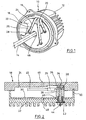
- Fig. 2 is a printed circuit board 30 indicated, which the electrical or electronic components for the so-called power part and the control part of a control device for the motor after Fig. 1 contains. These are not shown in detail and known per se. This includes in particular an inverter and a control device for operating the inverter.
- the printed circuit board 30 is mounted on one side of a heat sink 32.
- a head 34 of the bolt 28 is fixed in the engine shield 18, for example by gluing or other embedding on the side facing away from the engine of the shield 18.
- the bolt 28 extends through the cable lug 26, wherein between the cable lug 26 and motor plate 18 and bolt head 14, a plate spring 36 is arranged is.
- a spacer sleeve 38 is arranged made of electrically conductive material, which is supported on the circuit board 30. The sleeve 38 may additionally be soldered to the circuit board 30 to make electrical contact with the circuit board 30.
- a through hole which is aligned with a through hole in the circuit board 30 and in which a sleeve 40 is inserted from plastic material.
- the sleeve 40 extends into a recess of the spacer sleeve 38 inside, but is not frontally against the bottom of this recess.
- a flange 42 of the sleeve 40 abuts against the facing side of the heat sink 32.
- the bolt 28 has a threaded portion on which a nut 44 is screwed. How finally in Fig. 2 see motor shield 18 and circuit board 30 with heat sink 32 axially aligned openings 46 and 48, respectively, for the passage of the motor shaft 14th
- the plate spring 36 and then a cable lug over the associated pin 28 is placed.
- the engine plate 18 may be previously fixed to the housing 12, which is not shown in detail.
- Printed circuit board with heat sink and soldered sleeve 38 and inserted plastic sleeve 40 are then threaded onto the bolt 28. Subsequently, this arrangement is tightened against the engine plate 18 with the help of nuts. In this way, the control device is fixedly attached to an end face of the motor 10.
- the spring 36 ensures a sufficient bias of the sleeve 38 to the circuit board 30.
- the heat sink 30 is at the edge at 50 against the shield 18 tense and supported.
- Fig. 2 For reasons of illustration, only the connection of a cable 22 to the printed circuit board 30 is shown. It is understood that the connection of all three phase connections takes place in the same way. Also not shown is the connection of the DC power supply to the circuit board 30.
- the two DC cables are led laterally into the space between the printed circuit board 30 and motor plate 18 and electrically connected in a suitable manner with the circuit board 30. It is understood that this connection can be made in the same or similar manner as described in connection with the phase cables 22. This means that the two cables, for example, guided below the cable 22 in the space and also connected by means of bolts and spacers with the circuit board 30 electrically and mechanically.
- the axial through holes of the sleeve 38 and the sleeve 40 are significantly larger in diameter than the diameter of the bolt 28. In this way, tolerances when placing the unit of heat sink 32 and circuit board 30 can be compensated.
Landscapes
- Engineering & Computer Science (AREA)
- Power Engineering (AREA)
- Microelectronics & Electronic Packaging (AREA)
- Motor Or Generator Frames (AREA)
Claims (10)
- Moteur triphasé avec un dispositif de commande alimenté en courant continu, le dispositif de commande contenant un circuit imprimé (30) avec une partie de puissance et de commande qui est placé sur le carter du moteur, des connexions de phases (22) du moteur et une source de courant continu étant connectées électriquement au circuit imprimé (30) par le biais de contacts de connexion, le circuit imprimé (30) pouvant être fixé sur le côté extérieur d'une plaque de moteur (18), et les connexions de phases (22) isolées étant guidées, à travers au moins une ouverture (20) de la plaque de moteur (18), dans un espace intermédiaire vers le circuit imprimé (30), et étant connectées électriquement au circuit imprimé (30) par le biais de contacts de connexion, et des moyens de fixation étant prévus pour la fixation du circuit imprimé (30), caractérisé en ce que la plaque de moteur (18) se compose, au moins dans la zone des connexions de phases (22) ou des contacts de connexion, d'un matériau thermiquement résistant et électriquement isolant, le circuit imprimé (30) peut être fixé directement sur la plaque de moteur (18) par le biais des moyens de fixation, et les connexions de phases isolées sont guidées dans l'espace intermédiaire ente la plaque de moteur (18) et le circuit imprimé (30).
- Moteur triphasé selon la revendication 1, caractérisé en ce que le circuit imprimé (30) est placé sur le côté intérieur d'un radiateur (32) qui, de son côté, est serré contre la plaque de moteur (18) avec le circuit imprimé (30) par les moyens de fixation.
- Moteur triphasé selon la revendication 1 ou 2, caractérisé en ce que les connexions de phases (22) isolées sont guidées par le biais d'une ouverture (20) unique dans la plaque de moteur (18).
- Moteur triphasé selon une des revendications 1 à 3, caractérisé en ce que les connexions de phases (22) isolées passent dans des évidements (24) sur le côté extérieur de la plaque de moteur (18).
- Moteur triphasé selon une des revendications 1 à 4, caractérisé en ce que des cosses de câble (26) des connexions de phases (22) sont fixées sur la plaque de moteur (18) et sont en contact avec le circuit imprimé (30) par le biais d'une pièce de connexion électrique.
- Moteur triphasé selon la revendication 5, caractérisé en ce que la pièce de connexion est un corps d'écartement (38) électriquement conducteur qui est serré entre une cosse de câble (26) et le circuit imprimé (10).
- Moteur triphasé selon une des revendications 1 à 6, caractérisé en ce que, sur la plaque de moteur (18), il est fixé une extrémité (34) de plusieurs boulons (28) qui s'étendent de façon isolée à travers le circuit imprimé (30), et l'autre extrémité des boulons (28) présente un tronçon fileté sur lequel un écrou (44) peut être vissé pour la fixation du circuit imprimé (30) ou du radiateur (32) sur la plaque de moteur (18).
- Moteur triphasé selon la revendication 6 ou la revendication 7, caractérisé en ce que trois boulons (28) s'étendent respectivement à travers un perçage axial du corps d'écartement (38).
- Moteur triphasé selon la revendication 7 ou la revendication 8, caractérisé en ce que, dans des perçages du circuit imprimé (30) et du radiateur (32), est insérée une douille (40) en matériau isolant à travers laquelle s'étend respectivement un boulon (28).
- Moteur triphasé selon une des revendications 5 à 9, caractérisé en ce que, entre la plaque de moteur (18) et les cosses de câble (26), il est disposé respectivement un ressort (36), de préférence une rondelle-ressort.
Applications Claiming Priority (1)
| Application Number | Priority Date | Filing Date | Title |
|---|---|---|---|
| DE102006052583A DE102006052583A1 (de) | 2006-11-08 | 2006-11-08 | Drehstrommotor und Steuervorrichtung |
Publications (3)
| Publication Number | Publication Date |
|---|---|
| EP1921733A2 EP1921733A2 (fr) | 2008-05-14 |
| EP1921733A3 EP1921733A3 (fr) | 2008-08-20 |
| EP1921733B1 true EP1921733B1 (fr) | 2010-10-06 |
Family
ID=39092149
Family Applications (1)
| Application Number | Title | Priority Date | Filing Date |
|---|---|---|---|
| EP07019994A Revoked EP1921733B1 (fr) | 2006-11-08 | 2007-10-12 | Moteur triphasé et dispositif de commande |
Country Status (3)
| Country | Link |
|---|---|
| EP (1) | EP1921733B1 (fr) |
| CN (1) | CN101222164B (fr) |
| DE (2) | DE102006052583A1 (fr) |
Families Citing this family (4)
| Publication number | Priority date | Publication date | Assignee | Title |
|---|---|---|---|---|
| DE102016106104A1 (de) * | 2016-04-04 | 2017-10-05 | Linde Material Handling Gmbh | Elektrische Motoreinheit für mobile Arbeitsmaschine |
| DE102018124289A1 (de) * | 2018-10-02 | 2020-04-02 | Minebea Mitsumi Inc. | Elektromotor mit Leiterplatte zur elektrischen Kontaktierung der Motorwicklungen |
| EP4071979B1 (fr) * | 2019-12-06 | 2024-02-28 | Zhuhai Enpower Electric Co., Ltd. | Ensemble barre omnibus stratifiée, contrôleur de moteur, ensemble d'entraînement et véhicule |
| EP4277093A1 (fr) * | 2022-05-11 | 2023-11-15 | Siemens Aktiengesellschaft | Connexions soudées à courant élevé dans les machines dynamoélectriques |
Family Cites Families (11)
| Publication number | Priority date | Publication date | Assignee | Title |
|---|---|---|---|---|
| US4593163A (en) * | 1983-08-12 | 1986-06-03 | General Electric Company | Electric motors and method of manufacturing and operating same |
| DE8602197U1 (de) * | 1986-01-29 | 1988-11-17 | Hanning Elektro-Werke GmbH & Co, 4811 Oerlinghausen | Waschautomatenantrieb mit einem über einen Umrichter gespeisten Drehstrommotor |
| US4668898A (en) * | 1986-04-21 | 1987-05-26 | General Electric Company | Electronically commutated motor |
| DE3939738A1 (de) * | 1989-12-01 | 1991-06-06 | Telefunken Electronic Gmbh | Elektromotor mit einem luefterrad zum ansaugen von kuehlluft fuer kraftfahrzeuge |
| FR2689322B1 (fr) * | 1992-03-24 | 1994-05-13 | Valeo Equipements Elect Moteur | Dispositif a borne de prise de courant pour alternateur de vehicule automobile. |
| DE4418000C2 (de) * | 1994-05-21 | 1998-03-19 | Fhp Motors Gmbh | Elektronisch gesteuerter Elektromotor, insbesondere mit einem Lüfterrad zum Ansaugen von Kühlluft für Kraftfahrzeuge |
| JP3513338B2 (ja) * | 1996-10-09 | 2004-03-31 | 三菱電機株式会社 | 可変速電動機 |
| IT1289749B1 (it) * | 1996-12-13 | 1998-10-16 | Fiat Auto Spa | Sistema per collegare con angolazione prefissata un cavo elettrico a un morsetto di una apparecchiatura elettrica, in particolare un |
| US20020047488A1 (en) * | 1999-11-01 | 2002-04-25 | Scot Adams Webb | Powder coated insulated bolts |
| US6864616B2 (en) * | 2001-10-09 | 2005-03-08 | General Electric Company | Method and apparatus for forming an electric motor having stacked laminations |
| DE10161366A1 (de) * | 2001-12-14 | 2003-06-26 | Temic Auto Electr Motors Gmbh | Elektrische Antriebseinheit |
-
2006
- 2006-11-08 DE DE102006052583A patent/DE102006052583A1/de not_active Withdrawn
-
2007
- 2007-10-12 EP EP07019994A patent/EP1921733B1/fr not_active Revoked
- 2007-10-12 DE DE502007005258T patent/DE502007005258D1/de active Active
- 2007-11-02 CN CN200710169217.5A patent/CN101222164B/zh not_active Expired - Fee Related
Also Published As
| Publication number | Publication date |
|---|---|
| CN101222164B (zh) | 2015-07-01 |
| DE102006052583A1 (de) | 2008-05-15 |
| EP1921733A3 (fr) | 2008-08-20 |
| EP1921733A2 (fr) | 2008-05-14 |
| CN101222164A (zh) | 2008-07-16 |
| DE502007005258D1 (de) | 2010-11-18 |
Similar Documents
| Publication | Publication Date | Title |
|---|---|---|
| EP1532723B1 (fr) | Systeme destine a renfermer l'electronique de puissance et l'electronique de commande d'un moteur electrique | |
| EP2453560B1 (fr) | Groupe motopompe | |
| EP2320092B1 (fr) | Unité de pompage | |
| DE102006034991B4 (de) | Elektrische Servolenkungsvorrichtung | |
| DE3842588C2 (fr) | ||
| DE60128530T2 (de) | Einbau einer Steuerelektronik für bürstenlose Gleichstrommotoren in ihren Kühlkörper | |
| DE69400534T2 (de) | Verbindungsstruktur zum elektrischen Verbinden von Elektromotor und Motorregeleinheit | |
| DE69707226T2 (de) | Servolenkungseinrichtung mit Motor | |
| WO1999049554A1 (fr) | Moteur electrique pourvu en particulier d'une roue de ventilateur pour former un ventilateur axial ou radial | |
| DE112017001202T5 (de) | Elektrische Antriebsvorrichtung und elektrische Servolenkvorrichtung | |
| EP1059723B1 (fr) | Moteur avec boitier de connection | |
| DE112017001191T5 (de) | Elektrische Antriebsvorrichtung und elektrische Servolenkvorrichtung | |
| EP0853022B1 (fr) | Module de fonction pour véhicule. | |
| EP0368142B1 (fr) | Dispositif de commande électronique | |
| DE102016107079A1 (de) | Motorantriebssteuerung für ein Fahrzeug | |
| EP2909923A1 (fr) | Élément de raccordement pour un système d'entraînement ainsi que système d'entraînement comportant un élément de raccordement | |
| DE102005060282A1 (de) | Elektrische Servolenkungseinrichtung | |
| DE102012102335A1 (de) | Motoransteuervorrichtung und elektrische Servolenkeinrichtung, die diese aufweist | |
| EP1921733B1 (fr) | Moteur triphasé et dispositif de commande | |
| EP2716145A1 (fr) | Carte de circuits imprimés pour composants électriques et systèmes de cartes de circuits imprimés | |
| DE102022206596A1 (de) | Einzelphasenmodul eines Inverters, Inverter und Leistungselektronik | |
| DE10010439C2 (de) | Stellantrieb bzw. Verfahren zur Montage eines Stellantriebs | |
| DE102007014645A1 (de) | Elektrische Baugruppe, insbesondere für eine Lenkhilfe eines Kraftfahrzeuges | |
| EP2188839A1 (fr) | Appareil électronique et entraînement | |
| DE102004027653B4 (de) | Elektromotor |
Legal Events
| Date | Code | Title | Description |
|---|---|---|---|
| PUAI | Public reference made under article 153(3) epc to a published international application that has entered the european phase |
Free format text: ORIGINAL CODE: 0009012 |
|
| AK | Designated contracting states |
Kind code of ref document: A2 Designated state(s): AT BE BG CH CY CZ DE DK EE ES FI FR GB GR HU IE IS IT LI LT LU LV MC MT NL PL PT RO SE SI SK TR |
|
| AX | Request for extension of the european patent |
Extension state: AL BA HR MK RS |
|
| PUAL | Search report despatched |
Free format text: ORIGINAL CODE: 0009013 |
|
| AK | Designated contracting states |
Kind code of ref document: A3 Designated state(s): AT BE BG CH CY CZ DE DK EE ES FI FR GB GR HU IE IS IT LI LT LU LV MC MT NL PL PT RO SE SI SK TR |
|
| AX | Request for extension of the european patent |
Extension state: AL BA HR MK RS |
|
| 17P | Request for examination filed |
Effective date: 20080904 |
|
| AKX | Designation fees paid |
Designated state(s): CZ DE FR GB |
|
| GRAP | Despatch of communication of intention to grant a patent |
Free format text: ORIGINAL CODE: EPIDOSNIGR1 |
|
| GRAS | Grant fee paid |
Free format text: ORIGINAL CODE: EPIDOSNIGR3 |
|
| GRAA | (expected) grant |
Free format text: ORIGINAL CODE: 0009210 |
|
| AK | Designated contracting states |
Kind code of ref document: B1 Designated state(s): CZ DE FR GB |
|
| REG | Reference to a national code |
Ref country code: GB Ref legal event code: FG4D Free format text: NOT ENGLISH |
|
| REF | Corresponds to: |
Ref document number: 502007005258 Country of ref document: DE Date of ref document: 20101118 Kind code of ref document: P |
|
| PLBI | Opposition filed |
Free format text: ORIGINAL CODE: 0009260 |
|
| PG25 | Lapsed in a contracting state [announced via postgrant information from national office to epo] |
Ref country code: CZ Free format text: LAPSE BECAUSE OF NON-PAYMENT OF DUE FEES Effective date: 20101012 |
|
| PLAX | Notice of opposition and request to file observation + time limit sent |
Free format text: ORIGINAL CODE: EPIDOSNOBS2 |
|
| 26 | Opposition filed |
Opponent name: STILL GMBH Effective date: 20110706 |
|
| REG | Reference to a national code |
Ref country code: DE Ref legal event code: R026 Ref document number: 502007005258 Country of ref document: DE Effective date: 20110706 |
|
| PLAF | Information modified related to communication of a notice of opposition and request to file observations + time limit |
Free format text: ORIGINAL CODE: EPIDOSCOBS2 |
|
| PLBB | Reply of patent proprietor to notice(s) of opposition received |
Free format text: ORIGINAL CODE: EPIDOSNOBS3 |
|
| PLAY | Examination report in opposition despatched + time limit |
Free format text: ORIGINAL CODE: EPIDOSNORE2 |
|
| REG | Reference to a national code |
Ref country code: FR Ref legal event code: PLFP Year of fee payment: 9 |
|
| PLAH | Information related to despatch of examination report in opposition + time limit modified |
Free format text: ORIGINAL CODE: EPIDOSCORE2 |
|
| PLAL | Information related to reply to examination report in opposition modified |
Free format text: ORIGINAL CODE: EPIDOSCORE3 |
|
| PLBC | Reply to examination report in opposition received |
Free format text: ORIGINAL CODE: EPIDOSNORE3 |
|
| PLAY | Examination report in opposition despatched + time limit |
Free format text: ORIGINAL CODE: EPIDOSNORE2 |
|
| PLAH | Information related to despatch of examination report in opposition + time limit modified |
Free format text: ORIGINAL CODE: EPIDOSCORE2 |
|
| REG | Reference to a national code |
Ref country code: FR Ref legal event code: PLFP Year of fee payment: 10 |
|
| PLBC | Reply to examination report in opposition received |
Free format text: ORIGINAL CODE: EPIDOSNORE3 |
|
| PLAB | Opposition data, opponent's data or that of the opponent's representative modified |
Free format text: ORIGINAL CODE: 0009299OPPO |
|
| R26 | Opposition filed (corrected) |
Opponent name: STILL GMBH Effective date: 20110706 |
|
| REG | Reference to a national code |
Ref country code: FR Ref legal event code: PLFP Year of fee payment: 11 |
|
| REG | Reference to a national code |
Ref country code: DE Ref legal event code: R064 Ref document number: 502007005258 Country of ref document: DE Ref country code: DE Ref legal event code: R103 Ref document number: 502007005258 Country of ref document: DE |
|
| RDAF | Communication despatched that patent is revoked |
Free format text: ORIGINAL CODE: EPIDOSNREV1 |
|
| STAA | Information on the status of an ep patent application or granted ep patent |
Free format text: STATUS: THE PATENT HAS BEEN GRANTED |
|
| PGFP | Annual fee paid to national office [announced via postgrant information from national office to epo] |
Ref country code: CZ Payment date: 20171011 Year of fee payment: 11 Ref country code: FR Payment date: 20171031 Year of fee payment: 11 |
|
| PGFP | Annual fee paid to national office [announced via postgrant information from national office to epo] |
Ref country code: GB Payment date: 20171101 Year of fee payment: 11 |
|
| PGFP | Annual fee paid to national office [announced via postgrant information from national office to epo] |
Ref country code: DE Payment date: 20171229 Year of fee payment: 11 |
|
| RDAG | Patent revoked |
Free format text: ORIGINAL CODE: 0009271 |
|
| STAA | Information on the status of an ep patent application or granted ep patent |
Free format text: STATUS: PATENT REVOKED |
|
| 27W | Patent revoked |
Effective date: 20171214 |
|
| GBPR | Gb: patent revoked under art. 102 of the ep convention designating the uk as contracting state |
Effective date: 20171214 |