EP1921758A1 - Dispositif de reception radio et procédé de reception radio - Google Patents
Dispositif de reception radio et procédé de reception radio Download PDFInfo
- Publication number
- EP1921758A1 EP1921758A1 EP06301143A EP06301143A EP1921758A1 EP 1921758 A1 EP1921758 A1 EP 1921758A1 EP 06301143 A EP06301143 A EP 06301143A EP 06301143 A EP06301143 A EP 06301143A EP 1921758 A1 EP1921758 A1 EP 1921758A1
- Authority
- EP
- European Patent Office
- Prior art keywords
- transfer function
- information elements
- unit
- symbol
- domain transfer
- Prior art date
- Legal status (The legal status is an assumption and is not a legal conclusion. Google has not performed a legal analysis and makes no representation as to the accuracy of the status listed.)
- Withdrawn
Links
- 238000000034 method Methods 0.000 title claims description 28
- 238000012546 transfer Methods 0.000 claims abstract description 63
- 230000000694 effects Effects 0.000 claims abstract description 35
- 238000004364 calculation method Methods 0.000 claims description 10
- 230000001174 ascending effect Effects 0.000 claims 2
- 238000004088 simulation Methods 0.000 description 13
- 230000005540 biological transmission Effects 0.000 description 10
- 238000010586 diagram Methods 0.000 description 10
- 238000012545 processing Methods 0.000 description 9
- 238000004891 communication Methods 0.000 description 7
- 238000001514 detection method Methods 0.000 description 6
- 238000004422 calculation algorithm Methods 0.000 description 4
- 125000004122 cyclic group Chemical group 0.000 description 4
- 230000008569 process Effects 0.000 description 4
- 238000006243 chemical reaction Methods 0.000 description 3
- 238000005562 fading Methods 0.000 description 3
- 238000013507 mapping Methods 0.000 description 3
- 230000015556 catabolic process Effects 0.000 description 2
- 230000008859 change Effects 0.000 description 2
- 238000006731 degradation reaction Methods 0.000 description 2
- 238000003780 insertion Methods 0.000 description 2
- 230000037431 insertion Effects 0.000 description 2
- 230000006978 adaptation Effects 0.000 description 1
- 230000003044 adaptive effect Effects 0.000 description 1
- 239000000654 additive Substances 0.000 description 1
- 230000000996 additive effect Effects 0.000 description 1
- 230000001427 coherent effect Effects 0.000 description 1
- 238000011109 contamination Methods 0.000 description 1
- 230000003247 decreasing effect Effects 0.000 description 1
- 230000001934 delay Effects 0.000 description 1
- 230000003111 delayed effect Effects 0.000 description 1
- 238000001914 filtration Methods 0.000 description 1
- 238000012804 iterative process Methods 0.000 description 1
- 238000012986 modification Methods 0.000 description 1
- 230000004048 modification Effects 0.000 description 1
- 230000000737 periodic effect Effects 0.000 description 1
- 230000010363 phase shift Effects 0.000 description 1
- 230000004044 response Effects 0.000 description 1
- 230000003595 spectral effect Effects 0.000 description 1
Images






Classifications
-
- H—ELECTRICITY
- H04—ELECTRIC COMMUNICATION TECHNIQUE
- H04L—TRANSMISSION OF DIGITAL INFORMATION, e.g. TELEGRAPHIC COMMUNICATION
- H04L25/00—Baseband systems
- H04L25/02—Details ; arrangements for supplying electrical power along data transmission lines
- H04L25/0202—Channel estimation
- H04L25/0224—Channel estimation using sounding signals
- H04L25/0226—Channel estimation using sounding signals sounding signals per se
-
- H—ELECTRICITY
- H04—ELECTRIC COMMUNICATION TECHNIQUE
- H04L—TRANSMISSION OF DIGITAL INFORMATION, e.g. TELEGRAPHIC COMMUNICATION
- H04L25/00—Baseband systems
- H04L25/02—Details ; arrangements for supplying electrical power along data transmission lines
- H04L25/0202—Channel estimation
- H04L25/0224—Channel estimation using sounding signals
- H04L25/0228—Channel estimation using sounding signals with direct estimation from sounding signals
-
- H—ELECTRICITY
- H04—ELECTRIC COMMUNICATION TECHNIQUE
- H04L—TRANSMISSION OF DIGITAL INFORMATION, e.g. TELEGRAPHIC COMMUNICATION
- H04L25/00—Baseband systems
- H04L25/02—Details ; arrangements for supplying electrical power along data transmission lines
- H04L25/03—Shaping networks in transmitter or receiver, e.g. adaptive shaping networks
- H04L25/03006—Arrangements for removing intersymbol interference
- H04L25/03159—Arrangements for removing intersymbol interference operating in the frequency domain
-
- H—ELECTRICITY
- H04—ELECTRIC COMMUNICATION TECHNIQUE
- H04L—TRANSMISSION OF DIGITAL INFORMATION, e.g. TELEGRAPHIC COMMUNICATION
- H04L25/00—Baseband systems
- H04L25/02—Details ; arrangements for supplying electrical power along data transmission lines
- H04L25/03—Shaping networks in transmitter or receiver, e.g. adaptive shaping networks
- H04L25/03006—Arrangements for removing intersymbol interference
- H04L2025/0335—Arrangements for removing intersymbol interference characterised by the type of transmission
- H04L2025/03426—Arrangements for removing intersymbol interference characterised by the type of transmission transmission using multiple-input and multiple-output channels
-
- H—ELECTRICITY
- H04—ELECTRIC COMMUNICATION TECHNIQUE
- H04L—TRANSMISSION OF DIGITAL INFORMATION, e.g. TELEGRAPHIC COMMUNICATION
- H04L25/00—Baseband systems
- H04L25/02—Details ; arrangements for supplying electrical power along data transmission lines
- H04L25/03—Shaping networks in transmitter or receiver, e.g. adaptive shaping networks
- H04L25/03006—Arrangements for removing intersymbol interference
- H04L2025/03433—Arrangements for removing intersymbol interference characterised by equaliser structure
- H04L2025/03439—Fixed structures
- H04L2025/03522—Frequency domain
-
- H—ELECTRICITY
- H04—ELECTRIC COMMUNICATION TECHNIQUE
- H04L—TRANSMISSION OF DIGITAL INFORMATION, e.g. TELEGRAPHIC COMMUNICATION
- H04L25/00—Baseband systems
- H04L25/02—Details ; arrangements for supplying electrical power along data transmission lines
- H04L25/03—Shaping networks in transmitter or receiver, e.g. adaptive shaping networks
- H04L25/03006—Arrangements for removing intersymbol interference
- H04L2025/03433—Arrangements for removing intersymbol interference characterised by equaliser structure
- H04L2025/03535—Variable structures
- H04L2025/03541—Switching between domains, e.g. between time and frequency
-
- H—ELECTRICITY
- H04—ELECTRIC COMMUNICATION TECHNIQUE
- H04L—TRANSMISSION OF DIGITAL INFORMATION, e.g. TELEGRAPHIC COMMUNICATION
- H04L25/00—Baseband systems
- H04L25/02—Details ; arrangements for supplying electrical power along data transmission lines
- H04L25/03—Shaping networks in transmitter or receiver, e.g. adaptive shaping networks
- H04L25/03006—Arrangements for removing intersymbol interference
- H04L2025/03777—Arrangements for removing intersymbol interference characterised by the signalling
- H04L2025/03783—Details of reference signals
-
- H—ELECTRICITY
- H04—ELECTRIC COMMUNICATION TECHNIQUE
- H04L—TRANSMISSION OF DIGITAL INFORMATION, e.g. TELEGRAPHIC COMMUNICATION
- H04L25/00—Baseband systems
- H04L25/02—Details ; arrangements for supplying electrical power along data transmission lines
- H04L25/0202—Channel estimation
- H04L25/0212—Channel estimation of impulse response
-
- H—ELECTRICITY
- H04—ELECTRIC COMMUNICATION TECHNIQUE
- H04L—TRANSMISSION OF DIGITAL INFORMATION, e.g. TELEGRAPHIC COMMUNICATION
- H04L25/00—Baseband systems
- H04L25/02—Details ; arrangements for supplying electrical power along data transmission lines
- H04L25/0202—Channel estimation
- H04L25/022—Channel estimation of frequency response
Definitions
- the present invention relates to a radio receiving device and a radio receiving method. More specifically, the present invention relates to a radio receiving device and a radio receiving method which are adaptable for inter-symbol-interference and inter-carrier-interference.
- a single carrier (SC) system is used to a traditional digital transmission scheme in which data are transported as a fixed symbol rate serial stream of amplitude and/or phase modulated pulses.
- a linear frequency domain equalizer (FDE) performs receiver filtering in the frequency domain to minimize time domain inter symbol interference. Its function is the same as that of the time domain equalizer.
- linear frequency domain equalizer is simpler in term of computation complexity because equalization is performed by block of data. The operations on this block are the Fourier transform, channel compensation and the inverse Fourier transform.
- GI guard interval
- FIG. 18 summarizes the main steps of the transmit scheme. Transmit data are first encoded by the channel encode unit 101 and modulated to complex elements by the modulation unit 102. Then symbols are organized in blocks with length N.
- a cyclic prefix which is a copy of the last part of the transmitted block is included by a unit 103 as a header part of each block as shown in FIG. 19.
- the length of the cyclic prefix has to be longer than the maximum delay spread in order to completely avoid the inter symbol interference (ISI).
- the cyclic prefix at the beginning of each block has the following main functions: it prevents contamination of a block by ISI form the previous block and it makes the received block appear to be periodic with period N.
- a conventional receiving scheme is presented in FIG. 20.
- the cyclic prefix is discarded by the GI unit 501 and the serial-parallel converter 502 divides the output signal of the GI unit 501 for generating parallel signals each corresponding to a different received symbol.
- a fast Fourier transform (FFT) processing is performed on each block ofN data symbols by the discrete Fourier transform (DFT) unit 503. This FFT processing produces the appearance of circular convolution which is important for the FFT implementation.
- DFT discrete Fourier transform
- This FFT processing produces the appearance of circular convolution which is important for the FFT implementation.
- channel distortion is compensated for each sub-carrier and the inverse DFT (IDFT) unit 504 returns the equalized signal to the time domain.
- IDFT inverse DFT
- the parallel-serial unit 505 combines the output signal of the inverse DFT unit 504 and converts it into a serial signal prior to demodulating by the demodulation unit 507 and decoding of data symbols by the decode unit 508. This is disclosed by H. Sari, G. Karam and I. Jeanclaude, "Frequency-Domain Equalization of Mobile Radio and Terrestrial Broadcast Channels", Proc. Globecom. 1994. San Francisco. Nov-Dec. 1994. pp.1-5 .
- the rake receiver is known as a radio receiver designed to counter the effects of multipath fading, which is done by using several "sub-receivers.” Each sub-carrier is delayed slightly in order to tune in to the individual multipath components. Each component is decoded independently, but at a later stage combined in order to make the most use of the different transmission characteristics of each transmission path.
- This scheme of the rake receiver could very well result in higher signal-to-noise ratio (SNR) (or Eb/No) in a multipath environment than in a "clean" environment.
- SNR signal-to-noise ratio
- the rake receiver is so named because of its analogous function to a garden rake, each finger collecting bits or symbol energy similarly to how tines on a rake collect leaves.
- Rake receivers are common in a wide variety of CDMA (Code Division Multiple Access) and W-CDMA (Wideband-CDMA) radio devices.
- the object of the present invention is to provide a radio receiving device that can minimize the effects of interference and can be readily constituted, and a radio receiving method.
- the present invention is a radio receiving device that includes an antenna unit that receives a radio signal including a pilot symbol and a data symbol, a transfer function estimation unit that estimates a frequency domain transfer function and a time domain transfer function based on said received pilot symbol, a calculation unit which calculates information indicating the effects of interference based on the estimated frequency domain transfer function and time domain transfer function for each information element of sequential N information elements that are included in said pilot symbol, a block size selection unit that calculates, among said N information elements, a sequential range P with limited interference effects based on the calculated information indicating effects of interference, a data receiving unit that calculates a compensation value based on said sequential range P and the frequency domain transfer function estimated by said transfer function estimation unit and stores said compensation value, and, when said antenna receives a data symbol, calculates a received symbol consisting of the P information elements based on the received data symbol and said compensation value that is stored, a demodulation unit that demodulates said received symbol calculated by said data receiving unit; and a demodulation unit that demodulates said received
- FIG. 1 is a schematic block diagram showing a radio communication system 1 in which a single-carrier-based overlap frequency domain equalization (SC-OFDE) system, which is the principle of the present invention, is applied.
- Radio communication system 1 is provided with a combination of a radio transmitting device 2 and a radio receiving device 3a or a combination of a radio transmitting device 2 and a radio receiving device 3b.
- SC-OFDE single-carrier-based overlap frequency domain equalization
- a modulation unit 21 modulates transmission data by a modulation scheme such as Quadrature Phase-shift Keying (QPSK) or Quadrature Amplitude Modulation (QAM), and outputs a plurality of information elements that are expressed in bit strings after modulation.
- An antenna unit 22 transmits the modulated transmission data by a radio signal.
- an antenna unit 31 receives the radio signal from the radio transmitting device 2.
- a serial-parallel converter 32 performs parallel conversion on data received by the antenna 31 for each information element (hereinafter information elements are also referred to elements) modulated by the modulation unit 21, and outputs the converted data as a received symbol consisting of N information elements.
- information elements hereinafter information elements are also referred to elements
- An equalization unit 33 performs equalization on the received symbols that are input.
- An element selection unit 34 selects symbols consisting of P information elements with limited interference effects from the received symbols consisting of the N information symbols that are input.
- a demodulation unit 36 performs demodulation of the received symbols consisting of the P information elements that are input.
- a decoding unit 37 decodes the output from the demodulation unit 36.
- the radio receiving device 3b is provided with an equalization and element selection unit 38 that performs equalization on the received symbols that are input and selects symbols consisting of P information elements with limited interference effects from the received symbols consisting of the N information symbols.
- the function of the equalization and element selection unit 38 unifies the functions of the equalization unit 33 and the element selection unit 34 of the radio receiving device 3a.
- the other constitutions of the receiving device 3b are the same as those of the radio receiving device 3a.
- the propagation channel consists of M discrete paths having different amplitudes and time delays
- its base-band impulse response is represented as the following formula (F1).
- ⁇ m u is the complex channel gain of the m -th discrete path for the u-th active user
- ⁇ m u is the time delay of the m -th discrete path for the u -th active user.
- the total channel power is equal to 1. It is also assumed that coherent detection and perfect timing are performed.
- s m denotes the m-th modulated symbol which is transmitted during one frame. It is assumed that a frame is composed by N d data symbols and N p pilot symbols. Pilot symbols are necessary to estimate the channel variations.
- the concept of the proposed method consists of performing pseudo frequency domain equalization which is processed by the equalization unit 33 and the element selection unit 34 in the radio receiving device 3a and the equalization and element selection unit 38 in the radio receiving device 3b.
- the principle is to extract the appropriate consecutive elements which are denoted as N length from the plurality of consecutive received frames 4 and then perform N-point FFT on the extracted N length elements.
- the next step of the proposed equalization allows compensation of the channel variations on each element of the output of the FFT.
- N-point IFFT is performed on the N elements and one element, denoted x ⁇ p with 0 ⁇ p ⁇ N, is extracted. This equalization scheme is applied on the N d elements.
- N and P need to be carefully estimated
- the proposed method consists of first estimating the channel variation and then adjusting the two parameters by simply performing the proposed equalization scheme on the well-known sequence
- a first impression shows that N strongly depends on the modulation (QPSK, QAM).
- the received signal is written as the following formula (F2).
- r ⁇ h ⁇ ⁇ s ⁇ + n ⁇
- r , h , and n are, respectively, the received signal, the vector representation of the channel, and the additive white Gaussian noise (AWGN) vector representation.
- AWGN additive white Gaussian noise
- the equalization scheme closely approximates the SC-FDE system without GIs.
- the equalization is processed by the equalization unit 33 or the equalization and the element selection unit 38 is represented as the following formula (F3).
- output of the channel compensation is represented as the following formula (F4).
- the last part of the proposed equalization scheme consists of performing the N-point inverse FFT on the equalized signal z k and then one specific element defined by the index p is picked up by the element section unit 34 or the equalization and element selection unit 38.
- Output of the p-th element of the element section unit 34 or the equalization and element selection unit 38 is described by the following formula (F5).
- k ⁇ r m x ⁇ p is also described by the following formula (F8).
- the element section unit 34 or the equalization and element selection unit 38 estimates x ⁇ p and outputs x ⁇ p into the demodulation unit 36 through a parallel-serial converter 35.
- FIG. 3 is a block diagram showing the constitution of a radio receiving device 5 according to the first embodiment of the present invention.
- the ellipse figures in FIG. 3 indicate that connection lines equal to the number of the letter corresponding to the ellipse are contained in the ellipse. For example, if "N" appears on an ellipse, then N connection lines are present, and if "P" appears on an ellipse, then P connection lines are present.
- an antenna unit 51 receives a radio signal that has a frame constituted by a pilot information region and a data region as shown in FIG. 4.
- Np pilot symbols with GI are set
- N d data symbols are set.
- pilot symbols are formed in the state of the GI added.
- the transfer function estimation unit 50a estimates a time domain transfer function (h q ) and a frequency domain transfer function (H m ).
- the pilot symbol that is contained in the pilot information region of the radio signal frame received by the antenna unit 51 is input to a GI unit 52, where the guard interval is removed from the pilot symbol.
- the pilot symbol with the removed guard interval is then input to a serial-parallel unit 53.
- the serial-parallel unit 53 rearranges the input pilot symbols with the guard interval removed in parallel form for each information element and outputs them as received symbols consisting of N information elements.
- a DFT unit 54 performs the discrete Fourier transform (DFT) on the received symbols input from the serial-parallel unit 53, specifically performing the fast Fourier transform, for conversion to frequency domain received symbols.
- DFT discrete Fourier transform
- the output from the DFT unit 54 and a known symbol sequence stored in advance that is transmitted by the sending side are input to calculation units 55-1 to 55-N, which calculate the frequency domain transfer function H m based on the input information. Also, the calculation units 55-1 to 55-N output the calculated frequency domain transfer function H m to the inverse discrete Fourier transform (IDFT) unit 56, signal-to-interference and noise ratio (SINR) units 57-1 to 57-N, and equalization and element selection unit 62.
- the IDFT unit 56 performs the inverse discrete Fourier transform on the frequency domain transfer function H m , specifically performing the inverse fast Fourier transform for conversion to the time domain transfer function h q .
- the SINR units 57-1 to 57-N calculate N SINR (SINR (0) to SINR (N-1)) based on the frequency domain transfer function (H m ) and the time domain transfer function (h q ).
- a block size selection unit 58 calculates the value of P that indicates the aforementioned range of P information elements with limited interference effects based on N SINR of SINR (0) to SINR (N-1) input from the SINR units 57-1 to 57-N and an algorithm to be described below.
- a data receiving unit 60 data symbols contained in the data region of the radio signal frame received by the antenna unit 51 are input to a serial-parallel converter unit 61, which rearranges the data symbols in parallel form for each information element, and outputs them as received symbols r m consisting ofN information elements.
- an equalization and elements selection unit 62 performs the calculation of the aforementioned formula (F8) using the calculated compensation value w m p , and calculates the received symbol x ⁇ p consisting of P information elements with limited interference effects.
- a parallel-serial unit 63 converts the received symbols consisting of P information elements to serial data and outputs the data.
- a demodulation unit 64 performs demodulation of the received symbols consisting of the input P elements.
- a decoding unit 66 performs decoding on the output from the demodulation unit 64.
- a decision unit 65 is disposed between the demodulation unit 64 and the decoding unit 66, and a real value that is output from the demodulation unit 64 may be constituted so as to be output as binary data.
- the decoding system that is applied to the decoding unit 66 is determined based on a combination with the encoding method performed at the sending side. For example, in the case of the encoding unit employing the convolutional coding system, the Viterbi decoding system is applied in the decoding unit 66. In the case of the encoding unit employing the Turbo coding system, the MAP-based algorithm system is applied in the decoding unit 66. In the case of the LDPC coding system being employed in the encoding unit, the iterative process system is applied in the decoding unit 66.
- FIG. 6A and FIG 6B show the general principle of the frame processing the block size and the window length selection for the proposed detection scheme.
- the window length is N and the block size is P.
- FIG. 6A shows the i-th windowing application
- FIG. 6B shows the (i+1)-th windowing application.
- the block size is selected so that there is no overlapping in the i-th and (i+1)-th.
- selection of the appropriate window length N and the detection process of the block size P shall be explained.
- the block size selection unit 58 calculates the adaptation of the window and the block sizes based on the estimated SINR(0) to SINR(N-1) by the SINR unit 57-1 to 57-N.
- the inter carrier interference is represented by the following formula (F11).
- the frequency domain, representation of the received signal with interference is written as the following formula (F12).
- Z i,k is written as the following formula (F15).
- the numerator Ps is the signal power value of a received signal
- the first item of the denominator of formula (F18) is based on a signal power value of the received signal influenced by interference.
- the second item of the denominator of formula (F18) is based on signal power values of a noise signal.
- the SINR units 57-1 to 57-N can compute SINR based on the time domain transfer function (h q ), a frequency domain transfer function (H m ), G k , and ⁇ n 2 , where ⁇ n 2 is a variance of the noise signals.
- the SINR which described in the previous equations and the BER are linked and used to estimate both the window length and the block size in the function of the SINR.
- the window selection is based on the equation of the SINR and the coefficients for the equalization. There are two different ways to set up the window including the useful elements. These two ways are done by estimating the part strongly affected by the interference.
- the block size selection unit 58 executes the following algorithm.
- Judgment with formula (F19) is repeatedly performed by incrementing the value of p by one each until the formula (F19) above is satisfied.
- the value of p serves as the start point of the range of the block size P.
- Judgment with formula (F20) is repeatedly performed by decrementing the value of p by 1 each until the formula (F20) above is satisfied.
- the value of p serves as the end point of the range of the block size P.
- the block size selection unit 58 executes the following algorithm.
- Judgment with formula (F21) is repeatedly performed by incrementing the value of p by one each until the formula (F21) above is satisfied.
- the value of p serves as the start point of the range of the block size P.
- Processing based on formula (F21) can determine changes shown by the square of the absolute value of the SINR difference sequentially from the middle (N/2) to the front on the index axis of FIG. 7 and can detect N/2-p in which a variation is greater than a certain value ⁇ as the start point in the block size P.
- Judgment with formula (F22) is repeatedly performed by incrementing the value ofp by 1 each until the formula (F22) above is satisfied.
- the value of N/2-p serves as the end point of the range of the block size P.
- Processing based on formula (F22) can determine changes shown by the square of the absolute value of the SINR difference sequentially from the middle (N/2) to the back on the index axis of FIG. 7 and can detect N/2-p in which a variation is greater than a certain value ⁇ as the end point in the block size P.
- ⁇ is calculated as following.
- the largest SINR is estimated through N selected elements.
- the BER is estimated based on the estimated largest SINR, because the BER is a direct function of the SINR.
- the acceptable bit error rate is calculated based on the estimated BER depending on the system of the receiving device. Generally, a 1, 2, or 3% error rate will be accepted. Then the ⁇ is determined based on the acceptable error rate.
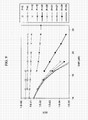
- Fig. 9 denotes the BER versus the SNR in some sample of block size P. It is highlighted through these simulation results that P should not be set up between N/2 and N.
- FIG. 10 shows the impact of the channel on the performance of the bit error rate (BER) in the function of the processed element in the frequency domain.
- line 10 denotes the performance of the single carrier frequency domain equalization (SC-FDE) with guard interval as a conventional scheme.
- Line 11 denotes the performance of the single carrier frequency domain equalization (SC-FDE) without a guard interval as a proposed scheme.
- Fig. 10 clearly highlights the impact of the ISI on the BER performance.
- Line 12 denotes the channel variation of both the conventional scheme and the proposed scheme.
- the line 13 denotes the impact of the inter-symbol-interference of both the conventional scheme and the proposed scheme.
- the ISI part as line 13 in the time domain representation is always placed at the beginning of the frame.
- the data receiving unit 60 may be constituted as the data receiving unit 60a, 60b of the radio receiving device 5a, 5b as shown in FIG. 11 and FIG. 12, respectively. These two schemes shown in FIG. 11 and 12 are identical but the representation is modified. FIG. 11 and FIG. 12 also show the radio transmitting device 2 which includes the proposed equalization method.
- the slide window selection unit 60a-1 selects the N size window as the input of the equalizer part and inputs selected N elements into the shift register unit 60a-2.
- the output of every register and w m p are input into each multiplier 60a-3.
- a slide window selection unit 60a-5 selects the P elements after the output of the adder 60a-4, which adds the output of every multiplier 60a-3.
- FIG. 12 shows another constitution of the data receiving unit.
- the data receiving unit 60b has the same performance as the data receiving unit 60a.
- the difference between the data receiving unit 60a and the data receiving unit 60b is that the data receiving unit 60b uses the N-point buffer unit 60b-2 wherein N symbols arrive together at a same time instead of the shift register unit 60a-2 wherein symbols arrive sequentially.
- the other components 60b-1, 60b-3, 60b-4 and 60b-5 of the data receiving unit 60b are each similar respectively to the selection unit 60a-1, the multiplier 60a-3, the adder 60a-4 and the slide window selection unit 60a-5 of the data receiving unit 60a.
- FIG. 13 is a block diagram showing the constitution of a radio receiving device 6 according to a second embodiment of the present invention.
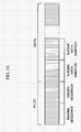
- the antenna unit 51 receives radio signals that have a frame constituted by a pilot information region and a data region as shown in FIG. 14.
- Np pilot symbols are set.
- a difference with the radio receiving device 5 of the first embodiment is also in the constitution of a transfer function estimation unit 50b.
- Other components are given the same reference numerals as those in the first embodiment.
- the constitution of the transfer function estimation unit 50b shall be described below.
- the transfer function estimation unit 50b similarly to the transfer function estimation unit 50a of the first embodiment, estimates a time domain transfer function (h q ) and a frequency domain transfer function (H m ).
- a time domain channel estimation unit 71 estimates the time domain transfer function (h q ) based on a pilot symbol that is received by the antenna unit 51 and a known symbol sequence stored in advance that is transmitted by the sending side.
- a channel estimation plus zero mapping unit 72 outputs anew the time domain transfer function (h q ) consisting of N values by mapping zero to the time domain transfer function (h q ) estimated by the time domain channel estimation unit 71 so that the number of values of the time domain transfer function (h q ) becomes N.
- a DFT unit 73 performs the discrete Fourier transform on the time domain transfer function (h q ) consisting of N values output from the channel estimation plus zero mapping unit 72, and outputs the frequency domain transfer function (H m ).
- the SINR units 57-1 to 57-N and the block size selection unit 58 performing identical processing as the constitution of the first embodiment, calculate a value of P that indicates the aforementioned range of P information elements with limited interference effects.
- the data receiving unit 60 may be constituted as the data receiving unit 60a, 60b of the radio receiving device 5a, 5b as shown in FIG. 11 and FIG. 12, respectively.
- FIG. 15 is a drawing showing a radio communication system 100 of the multiple input-multiple output (MIMO) transmission method according to the third embodiment of the present invention.
- the radio communication system 100 is provided with a radio transmitting device 200 and a radio receiving device 300.
- the radio transmitting device 200 is provided with Nt antennas 201-1 to 201-Nt and Nt modulation units 202-1 to 202-Nt.
- the radio receiving device 300 is provided with a plurality of antennas 301-1 to 301-Nr, data receiving unit 302, demodulation unit 303, and decoding unit 304.
- the signal model is represented as the following formula (F23).
- r m q is the m-th symbol in the buffer sequence on the q-th receiving antenna 301-q of the radio receiving device 300.
- the output of the channel compensation is represented as the following formula (F24).
- the last part of the proposed equalization method consists of performing the N-point inverse FFT on the equalized signal z k p and then one specific element, which is defined by the index u, is picked up.
- the output of the u-th element of the data receiving unit 302 of the radio receiving device 300 is described as the following formula (F25).
- x ⁇ u p is output from the data receiving unit 302 and these elements are sent through the demodulation unit 303.
- the log values of the 4 different channels (2x2) are also presented. It is observed that the value of u (index of the output of the data receiving unit 302) strongly affects the BER performance.
- the proposed equalization scheme exhibits similar performance to the conventional scheme, even though the proposed equalization scheme is a relatively low complexity system compared with the conventional scheme which includes GI and the proposed equalization scheme.
- FIG. 17 shows the performance simulations for the proposed scheme, the conventional SC-FDE with GI according to the solid line and the SC-FDE without GI according to the dot-and-dash line.
- the proposed scheme according to the dashed line (equalizer without any guard interval)
- the proposed scheme strongly outperforms it.
- BER performances are similar in spite of the constitution without GI.
- the GI insertion reduces the spectral efficiency of the receiving device.
- it is necessary to roughly estimate the GI value Generally, the value is fixed to 20 or 25% of the symbol duration.
- the radio receiving device enables selection of the window length including useful elements with limited interference effects based on the pilot symbol and detection of the block size corresponding to the useful elements. Also, the radio receiving device enables equalizing only one symbol using windowing. Thereby, the radio receiving device reduces complexity and limits performance degradation. Also, the radio receiving device can obtain the output of the equalization in the time domain. In addition, the radio receiving device has the effect of few performance variations for a certain number of elements. Also, the radio receiving device has the effect of the possibility of optimizing the selecting window length. Also, the present invention enables minimizing the effect of inter-symbol-interference and inter-carrier-interference with a constitution only at the receiving side.
- data which indicate effects of the ISI and ICI or which are derived from effects such as the power of the interference, the associate BER, and the like can be used to estimate the window in the present invention in place of the SINR as explained in the embodiments.
- the present invention can be used to prevent the single carrier radio communication system from being affected by interference.
Landscapes
- Engineering & Computer Science (AREA)
- Power Engineering (AREA)
- Computer Networks & Wireless Communication (AREA)
- Signal Processing (AREA)
- Cable Transmission Systems, Equalization Of Radio And Reduction Of Echo (AREA)
Priority Applications (1)
| Application Number | Priority Date | Filing Date | Title |
|---|---|---|---|
| EP06301143A EP1921758A1 (fr) | 2006-11-10 | 2006-11-10 | Dispositif de reception radio et procédé de reception radio |
Applications Claiming Priority (1)
| Application Number | Priority Date | Filing Date | Title |
|---|---|---|---|
| EP06301143A EP1921758A1 (fr) | 2006-11-10 | 2006-11-10 | Dispositif de reception radio et procédé de reception radio |
Publications (1)
| Publication Number | Publication Date |
|---|---|
| EP1921758A1 true EP1921758A1 (fr) | 2008-05-14 |
Family
ID=38227824
Family Applications (1)
| Application Number | Title | Priority Date | Filing Date |
|---|---|---|---|
| EP06301143A Withdrawn EP1921758A1 (fr) | 2006-11-10 | 2006-11-10 | Dispositif de reception radio et procédé de reception radio |
Country Status (1)
| Country | Link |
|---|---|
| EP (1) | EP1921758A1 (fr) |
Cited By (1)
| Publication number | Priority date | Publication date | Assignee | Title |
|---|---|---|---|---|
| CN118869410A (zh) * | 2024-07-19 | 2024-10-29 | 西安电子科技大学 | 一种在扩频sc-fde系统中实现多径分集的均衡器 |
Citations (2)
| Publication number | Priority date | Publication date | Assignee | Title |
|---|---|---|---|---|
| US20040213339A1 (en) * | 2003-04-24 | 2004-10-28 | Smee John E. | Equalizer |
| WO2006020657A2 (fr) * | 2004-08-09 | 2006-02-23 | Texas Instruments Incorporated | Egalisation dans le domaine des frequences |
-
2006
- 2006-11-10 EP EP06301143A patent/EP1921758A1/fr not_active Withdrawn
Patent Citations (2)
| Publication number | Priority date | Publication date | Assignee | Title |
|---|---|---|---|---|
| US20040213339A1 (en) * | 2003-04-24 | 2004-10-28 | Smee John E. | Equalizer |
| WO2006020657A2 (fr) * | 2004-08-09 | 2006-02-23 | Texas Instruments Incorporated | Egalisation dans le domaine des frequences |
Non-Patent Citations (1)
| Title |
|---|
| N. SHARMA, A TIKKU: "Is the cyclic prefix necessary?", 2006 IEEE INTERNATIONAL SYMPOSIUM ON INFORMATION THEORY, SEATTLE , USA, 9 July 2006 (2006-07-09) - 12 July 2006 (2006-07-12), Piscataway, USA, pages 128 - 132, XP002442385 * |
Cited By (1)
| Publication number | Priority date | Publication date | Assignee | Title |
|---|---|---|---|---|
| CN118869410A (zh) * | 2024-07-19 | 2024-10-29 | 西安电子科技大学 | 一种在扩频sc-fde系统中实现多径分集的均衡器 |
Similar Documents
| Publication | Publication Date | Title |
|---|---|---|
| KR100996535B1 (ko) | 다중입출력 안테나 직교주파수 분할 다중화 시스템의 셀간 간섭 완화를 위한 공간 공분산 행렬 추정 기법을 이용한 셀간 간섭 완화 방법 및 이를 이용한 셀간 간섭 완화 수신 장치 | |
| KR100693778B1 (ko) | 트레이닝 프리픽스 변조 방법 및 수신기 | |
| US7082159B2 (en) | Methods and arrangements in a telecommunications system | |
| US8462899B2 (en) | Multi-user detecting method and device of OFDM transmission signal | |
| Han et al. | Iterative per-vector equalization for orthogonal signal-division multiplexing over time-varying underwater acoustic channels | |
| EP2605463B1 (fr) | Procédé d'estimation de trajet de propagation et appareil | |
| JP4189477B2 (ja) | Ofdm(直交周波数分割多重)適応等化受信方式及び受信機 | |
| JP4421416B2 (ja) | Ofdm方式の受信装置 | |
| JP4854094B2 (ja) | 無線受信機、無線通信システムおよび無線受信方法 | |
| EP1335518A1 (fr) | Réception de signaux multiporteurs à spectre étalé | |
| JP2006067070A (ja) | Mimoシステム受信方法及びその装置 | |
| JP4130821B2 (ja) | 多重アンテナを使用する直交周波数分割多重システムでの干渉信号を除去する装置及び方法 | |
| EP2547015A1 (fr) | Dispositif de réception, procédé de réception, programme de réception et processeur | |
| JP2006262039A (ja) | 伝搬路推定方法及び伝搬路推定装置 | |
| KR100849338B1 (ko) | 직교주파수분할다중 방식의 이동통신시스템에서시공간-주파수 부호화/복호화 장치 및 방법 | |
| US6973134B1 (en) | OFDM interference cancellation based on training symbol interference | |
| CN102362493A (zh) | 用于单载波地面数字电视接收机的均衡器 | |
| JP2003218826A (ja) | 直交周波数分割多重信号の受信方式及び受信機 | |
| JP4272665B2 (ja) | Ofdm伝送システムのチャネルを推定する装置、方法、及びコンピュータプログラム | |
| Dinis et al. | IB‐DFE receivers with space diversity for CP‐assisted DS‐CDMA and MC‐CDMA systems | |
| CN101689954A (zh) | 接收机以及接收方法 | |
| US8718162B2 (en) | Reception device, reception method, and reception program | |
| Hunziker et al. | Iterative detection for multicarrier transmission employing time-frequency concentrated pulses | |
| EP1921758A1 (fr) | Dispositif de reception radio et procédé de reception radio | |
| US7248849B1 (en) | Frequency domain training of prefilters for receivers |
Legal Events
| Date | Code | Title | Description |
|---|---|---|---|
| PUAI | Public reference made under article 153(3) epc to a published international application that has entered the european phase |
Free format text: ORIGINAL CODE: 0009012 |
|
| AK | Designated contracting states |
Kind code of ref document: A1 Designated state(s): AT BE BG CH CY CZ DE DK EE ES FI FR GB GR HU IE IS IT LI LT LU LV MC NL PL PT RO SE SI SK TR |
|
| AX | Request for extension of the european patent |
Extension state: AL BA HR MK RS |
|
| AKX | Designation fees paid | ||
| REG | Reference to a national code |
Ref country code: DE Ref legal event code: 8566 |
|
| STAA | Information on the status of an ep patent application or granted ep patent |
Free format text: STATUS: THE APPLICATION IS DEEMED TO BE WITHDRAWN |
|
| 18D | Application deemed to be withdrawn |
Effective date: 20081115 |