EP1921780A2 - Vorrichtung zur Signalteilung und Videogerät damit - Google Patents
Vorrichtung zur Signalteilung und Videogerät damit Download PDFInfo
- Publication number
- EP1921780A2 EP1921780A2 EP07112077A EP07112077A EP1921780A2 EP 1921780 A2 EP1921780 A2 EP 1921780A2 EP 07112077 A EP07112077 A EP 07112077A EP 07112077 A EP07112077 A EP 07112077A EP 1921780 A2 EP1921780 A2 EP 1921780A2
- Authority
- EP
- European Patent Office
- Prior art keywords
- broadcast signal
- broadcast
- splitting
- processing element
- signal processing
- Prior art date
- Legal status (The legal status is an assumption and is not a legal conclusion. Google has not performed a legal analysis and makes no representation as to the accuracy of the status listed.)
- Withdrawn
Links
Images


Classifications
-
- H—ELECTRICITY
- H04—ELECTRIC COMMUNICATION TECHNIQUE
- H04H—BROADCAST COMMUNICATION
- H04H40/00—Arrangements specially adapted for receiving broadcast information
- H04H40/18—Arrangements characterised by circuits or components specially adapted for receiving
-
- H—ELECTRICITY
- H04—ELECTRIC COMMUNICATION TECHNIQUE
- H04N—PICTORIAL COMMUNICATION, e.g. TELEVISION
- H04N5/00—Details of television systems
- H04N5/44—Receiver circuitry for the reception of television signals according to analogue transmission standards
-
- H—ELECTRICITY
- H04—ELECTRIC COMMUNICATION TECHNIQUE
- H04N—PICTORIAL COMMUNICATION, e.g. TELEVISION
- H04N7/00—Television systems
- H04N7/10—Adaptations for transmission by electrical cable
- H04N7/102—Circuits therefor, e.g. noise reducers, equalisers, amplifiers
- H04N7/104—Switchers or splitters
-
- H—ELECTRICITY
- H04—ELECTRIC COMMUNICATION TECHNIQUE
- H04H—BROADCAST COMMUNICATION
- H04H20/00—Arrangements for broadcast or for distribution combined with broadcast
- H04H20/02—Arrangements for relaying broadcast information
- H04H20/08—Arrangements for relaying broadcast information among terminal devices
Definitions
- the present invention relates generally to an apparatus for splitting a signal, and a video device using the same. More particularly, but not exclusively, the present invention relates to an apparatus for splitting a signal, which splits a single broadcast signal into a plurality of broadcast signals, and a video device using the same.
- a conventional signal splitting apparatus usually uses amplifiers.
- amplifiers belong to the active element, with use of the amplifiers, a problem occurs, in that, the NF of the broadcast signals is increased all the more.
- the amplifiers require bias in operation.
- the bias is changed, the broad signals are influenced by the changed bias, so that a gain thereof is changed. Accordingly, a problem occurs, in that broadcast signal processing elements, which require a certain gain of broadcast signals, generate errors in signal processing.
- an aim of embodiments of the present invention is to address at least the above problems and/or disadvantages and to provide at least some of the advantages described below. Accordingly, embodiments of the present invention aim to provide an apparatus for splitting a signal capable of distributing and providing a broadcast signal with a noise figure (NF) lower than that of other broadcast signals, to an element, which requires a broadcast signal with a low NF, and a video device using the same.
- NF noise figure
- Another aim of embodiments of the present invention is to provide an apparatus for splitting a signal, which splits an inputted broadcast signal without using an active element, such as an amplifier or the like, thereby allowing split broadcast signals to lower a NF thereof and to uniformly maintain a gain thereof, and a video device using the same.
- Still another aim of embodiment of the present invention is to provide an apparatus for splitting a signal capable of preventing or minimizing interferences, which are generated between adjacent ports, and a video device using the same.
- an apparatus for splitting a signal including a first splitting unit to split an inputted broadcast signal into a first broadcast signal and a second broadcast signal, and to supply the first broadcast signal to a first broadcast signal processing element, and a second splitting unit to split the second broadcast signal into a third broadcast signal and a fourth broadcast signal, and to supply the third broadcast signal to a second broadcast signal processing element.
- the second splitting unit may supply the fourth broadcast signal to a third broadcast signal processing element.
- the first broadcast signal processing element includes a broadcast signal processing element to require a broadcast signal having a noise figure lower than that of the second and the third broadcast signal processing elements.
- the apparatus further includes a third splitting unit to split the fourth broadcast signal into a fifth broadcast signal and a sixth broadcast signal, and to supply the fifth broadcast signal to a third broadcast signal processing element and supply the sixth broadcast signal to a fourth broadcast signal processing element.
- a third splitting unit to split the fourth broadcast signal into a fifth broadcast signal and a sixth broadcast signal, and to supply the fifth broadcast signal to a third broadcast signal processing element and supply the sixth broadcast signal to a fourth broadcast signal processing element.
- the apparatus further includes an isolating element disposed between the second splitting unit and the third splitting unit to isolate between input ends of the first and the second broadcast signal processing elements and input ends of the third and the fourth broadcast signal processing elements.
- the isolating element may block a leakage of at least one of the first and the second broadcast signal processing elements from exerting influence on at least one of the third and the fourth broadcast signal processing elements.
- the isolating element includes a transformer in which a winding ratio of an input side to an output side is 1: n.
- the third splitting unit includes a transformer to split the fourth broadcast signal in a splitting ratio of n: 1.
- the n may be a real number larger than 1.
- the fourth broadcast signal processing element includes a broadcast signal processing element to require a broadcast signal having a noise figure and a change in gain, which are lower than those of the third broadcast signal processing element.
- the first broadcast signal processing element may be an element to select a broadcast channel to be displayed on a main screen
- the second broadcast signal processing element may be an element to select a broadcast channel to be displayed on a sub-screen
- the third broadcast signal processing element may be an element to extract additional information included in the broadcast signal
- the fourth broadcast signal processing element may be an element to provide a data communication using a modem.
- the isolating element has input impedance higher than an impedance connected to an output end thereof.
- the inputted broadcast signal includes a cable broadcast signal received through a cable, satellite broadcast signal, IPTV broadcast signal or other types of broadcast signals.
- a video device including a broadcast receiving unit to receive a broadcast signal, a signal splitting apparatus to split the broadcast signal received by the broadcast receiving unit into a plurality of broadcast signals, and a broadcast processing module to process the broadcast signals split by the signal splitting apparatus.
- the signal splitting apparatus includes a first splitting unit to split the broadcast signal received by the broadcast receiving unit into a first broadcast signal and a second broadcast signal, and to supply the first broadcast signal to a first broadcast signal processing element disposed in the broadcast processing module, and a second splitting unit to split the second broadcast signal into a third broadcast signal and a fourth broadcast signal, and to supply the third broadcast signal to a second broadcast signal processing element disposed in the broadcast processing module.
- the device may further include a broadcast displaying module to display the broadcast signals processed by the broadcast processing module.
- the signal splitting apparatus further includes a third splitting unit to split the fourth broadcast signal into a fifth broadcast signal and a sixth broadcast signal, and to supply the fifth broadcast signal to a third broadcast signal processing element disposed in the broadcast processing module and supply the sixth broadcast signal to a fourth broadcast signal processing element disposed in the broadcast processing module.
- a third splitting unit to split the fourth broadcast signal into a fifth broadcast signal and a sixth broadcast signal, and to supply the fifth broadcast signal to a third broadcast signal processing element disposed in the broadcast processing module and supply the sixth broadcast signal to a fourth broadcast signal processing element disposed in the broadcast processing module.
- the signal splitting apparatus further includes an isolating element disposed between the second splitting unit and the third splitting unit to isolate between input ends of the first and the second broadcast signal processing elements and input ends of the third and the fourth broadcast signal processing elements.
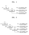
- FIG. 1 is a block diagram exemplifying an apparatus for splitting a signal in accordance with a first embodiment of the present invention. As illustrated in FIG. 1, the signal splitting apparatus in accordance with the first embodiment of the present invention is provided with a first splitting unit 110-1 and a second splitting unit 110-2.
- the first splitting unit 110-1 splits an inputted broadcast signal (referred as BS below) into a first broadcast signal (referred as BS-1 below) and a second broadcast signal (referred as BS-2 below).
- the BS inputted to the first splitting unit 110-1 may be a cable broadcast signal, which is received through a cable.
- the split BS-1 is split no longer, but supplied to a first broadcast processing element A.
- the split BS-2 is re-split.
- the second splitting unit 110-2 re-splits the BS-2 split by the first splitting unit 110-1 into a third broadcast signal (referred as BS-3 below) and a fourth broadcast signal (referred as BS-4 below).
- the re-split BS-3 is supplied to a second broadcast signal processing element B
- the re-split BS-4 is supplied to a third broadcast processing element C.
- the BS-1 has a noise figure (NF) lower than that of the BS-3 or the BS-4.
- NF noise figure
- the BS-1 is a broadcast signal, which has less split number of times than that of the BS-3 or the BS-4.
- the first broadcast processing element A when the first broadcast processing element A is embodied in a broadcast processing element, which requires a broadcast signal with a NF lower than that of the second broadcast signal processing element B or the third broadcast signal processing element C (that is, when a broadcast processing element, which requires a broadcast signal with a low NF, is embodied to receive the BS-1), more superior performance can be obtained.
- FIG. 2 is a block diagram exemplifying an apparatus for splitting a signal in accordance with a second embodiment of the present invention.
- the signal splitting apparatus illustrated in FIG. 2 further includes a splitting unit as compared with the signal splitting apparatus illustrated in FIG. 1. Namely, the signal splitting apparatus illustrated in FIG. 2 further includes a third splitting unit 110-3 in addition to a first splitting unit 110-1 and a second splitting unit 110-2.
- the first splitting unit 110-1 is equal to the first splitting unit 110-1 illustrated in FIG 1, in that it splits an inputted BS into a BS-1 and a BS-2 and supplies the split BS-1 to a first broadcast signal processing element A.
- the second splitting unit 110-2 is similar to the second splitting unit 110-2 illustrated in FIG. 1, in that it re-splits the BS-2 split by the first splitting unit 110-1 into a BS-3 and a BS-4 and supplies the re-split BS-3 to a second broadcast signal processing element B.
- the second splitting unit 110-2 illustrated in FIG. 2 is different from the second splitting unit 110-2 illustrated in FIG. 1, in that it does not supply the re-split BS-4 to a third broadcast processing element C, but to the third splitting unit 110-3.
- the third splitting unit 110-3 re-splits the BS-4 re-split by the second splitting unit 110-2 into a fifth broadcast signal (referred as BS-5 below) and a sixth broadcast signal (referred as BS-6 below). And the third splitting unit 110-3 supplies the re-split BS-5 to the third broadcast signal processing element C, and supplies the re-split BS-6 to a fourth broadcast processing element D.
- BS-5 broadcast signal
- BS-6 sixth broadcast signal
- the BS-1 has a NF lower than that of the BS-3, the BS-5 or the BS-6.
- the reason is that the BS-1 is a broadcast signal, which has less split number of times than that of the BS-3, the BS-5 or the BS-6.
- the BS-3 has a NF lower than that of the BS-5 or the BS-6.
- the reason is that the BS-3 is a broadcast signal, which has less split number of times than that of the BS-5 or the BS-6.
- the first broadcast processing element A is embodied in a broadcast processing element, which requires a broadcast signal with the lowest NF and the second broadcast processing element B is embodied in a broadcast processing element, which requires a broadcast signal with the next-lowest NF, more superior performance can be obtained.
- FIG. 3 is a block diagram exemplifying an apparatus for splitting a signal in accordance with a third embodiment of the present invention.
- the signal splitting apparatus illustrated in FIG. 3 further includes an isolating element as compared with the signal splitting apparatus illustrated in FIG. 2.
- the signal splitting apparatus illustrated in FIG. 3 further includes an isolating unit 120 in addition to a first splitting unit 110-1, a second splitting unit 110-2, and a third splitting unit 110-3.
- the isolating unit 120 is disposed between the second splitting unit 110-2 and the third splitting unit 110-3.
- the isolating unit 120 is an element for isolating between input ends of first and second broadcast signal processing elements A and B and input ends of third and fourth broadcast signal processing elements C and D.
- the isolating unit 120 With the isolating unit 120, the influence of a leakage from the first and/or the second broadcast signal processing elements A and/or B on the third and/or the fourth broadcast signal processing elements C and/or D can be blocked.
- FIG. 4 is a circuit diagram of the signal splitting apparatus illustrated in FIG. 3. Referring to FIG. 4, it can be appreciated that each of the first and the second splitting units 110-1 and 110-2 was embodied by using a transformer splitting an inputted signal in a splitting ratio of 1:1 and a resistance for impedance matching.
- the first broadcast signal processing element A was embodied in a main tuner, which selects a broadcast channel to be displayed on a main screen
- the second broadcast signal processing element B was embodied in a sub-tuner, which selects a broadcast channel to be displayed on a sub-screen. This is because a broadcast signal with the lowest NF is preferably supplied to the main tuner and a broadcast signal with the next-lowest NF is preferably supplied to the sub-tuner.
- the third broadcast signal processing element C was embodied in an out-of-band (OOB) processing element for carrying out an OOB function
- the fourth broadcast signal processing element D was embodied in a data-over-cable service interface specification (DOCSIS) modem for carrying out a DOCSIS function
- OOB function is a kind of function, which extracts additional information included in the broadcast signal to provide visual information to a user such as EPG information
- DOCSIS function is a kind of function, which provides a data communication between a broadcasting provider and the user by using a cable modem.
- None of the OOB function and the DOCSIS function concerns a function, which provides an image on a screen. Accordingly, the OOB processing element and the DOCSIS modem, which use the additional information and the data having an amount smaller than that of the image, respectively, were embodied, so that broadcast signals having a NF higher than that of the broadcast signals supplied to the main tuner and the sub-tuner are supplied thereto, respectively.
- the isolating unit 120 was embodied in a transformer in which a winding ratio of an input side to an output side is 1:3. Since an input impedance of the transformer in which the winding ratio is 1:3 is 3 2 times of impedance at an output end thereof, the transformer in which the winding ratio is 1:3 belongs to the impedance converting element, which causes the input impedance to increase.
- the third splitting unit 110-3 was embodied by using a transformer splitting an inputted signal in a splitting ratio of 3:1 and a resistance for impedance matching.
- the splitting ratio of the third splitting unit 110-3 is different from that of the first and the second splitting units 110-1 or 110-2, in that it is set as 3:1.
- the DOCSIS modem is an element relatively sensitive to a NF and a change in gain of the broadcast signal, to allow the broadcast signal supplied thereto to lower the NF and to uniformly maintain the gain
- the splitting ratio of the third splitting unit 110-3 was set to be different from that of the first and the second splitting units 110-1 or 110-2. Detailed description on that is as follows.
- the input impedance to the DOCSIS modem at the input end of the third splitting unit 110-3 is relatively small. Accordingly, due to the third splitting unit 110-3, the influence of the input impedance of the isolating unit 120 increased by the isolating unit 120 as described above on the DOCSIS modem is compensated.
- impedance characteristic from the input end of the isolating unit 120 to the input end of the DOCSIS modem is uniformly maintained, so that the NF of the broadcast signal supplied to the DOCSIS modem is lowered and the gain of the broadcast signal supplied to the DOCSIS modem is also uniformly maintained.
- the broadcast signal supplied to the DOCSIS modem has lower NF and more uniform gain than those of the broadcast signal supplied to the OOB processing element.
- Capacitors disposed between the splitting units 110-1, 110-2 and 110-3 and the isolating unit 120 illustrated in FIG. 4 are elements, which are used for DC blocking.
- first and the second splitting units 110-1 and 110-2 illustrated in FIG. 4 are explained as embodied in the transformers in which the splitting ratio is 1:1, it goes without saying that they can be embodied in transformers with different splitting ratio.
- the isolating unit 120 is explained as embodied in the transformer in which the winding ratio of the input end to the output end is 1:3, it goes without saying that it can be embodied in a transformer with different winding ratio. Namely, the isolating unit 120 can be embodied in a transformer in which the winding ratio of the input end to the output end is 1:n.
- n is a real number larger than 1. This is because if so, the isolating unit 120 can be embodied to have an increased input impedance.
- the third splitting unit 110-3 is embodied in a transformer in which the splitting ratio is n: 1. The reason is that if so, the influence of the input impedance of the isolating unit 120 increased by the isolating unit 120 on the DOCSIS modem is compensated by the third splitting unit 110-3, so that the NF of the broadcast signal supplied to the DOCSIS modem can be lowered.
- the signal splitting apparatus illustrated in FIGS. 3 and 4 is explained and illustrated as having a single isolating unit 120, it can be embodied to have more than two isolating units.
- the signal splitting apparatus can be embodied, so that another isolating unit is disposed between the first splitting unit 110-1 and the second splitting unit 110-2, thereby isolating the input end of the main tuner and the input end of the sub-tuner from each other.
- FIGS. 2 and 3 are explained and illustrated as embodied by using three splitting units, it can be embodied to have more than four splitting units in the same technical sprit and principle.
- FIG. 5 is a block diagram exemplifying the video device, which is realized by employing the signal splitting apparatus.
- the video device is provided with a broadcast receiving unit 210, a signal splitting apparatus 100, a broadcast processing module 220, and a broadcast displaying module 230.
- the broadcast receiving unit 210 receives a broadcast signal and transmits the received broadcast signal to the signal splitting apparatus 100.
- the broadcast receiving unit 210 can receive a cable broadcast signal through a cable.
- the signal splitting apparatus 100 splits the broadcast signal transmitted from the broadcast receiving unit 210 into a plurality of broadcast signals.
- the signal splitting apparatus 100 may be any one of the signal splitting apparatuses illustrated in FIGS. 1 through 4.
- the broadcast processing module 220 is a module, which processes the broadcast signals split by the signal splitting apparatus 100 to provide a broadcast signal processing function, a OOB function, a DOCSIS function, etc.
- the main tuner, the sub-tuner, the OOB processing element, the DOCSIS modem and the like as explained with reference to FIGS. 1 through 4 are included in the broadcast processing module 220.
- the broadcast displaying module 230 is a display element on which broadcast information, visual information and the like processed by the broadcast processing module 220 are displayed.
- the present invention will not limit to include all of the blocks illustrated FIG. 5 in the video device, and unnecessary blocks can be omitted from the video device.
- a TV should include all of the blocks illustrated FIG. 5, but a set top box (STB) can omit the broadcast displaying module 230.
- STB set top box
- the signal splitting apparatus and the video device using the same can distribute and provide the broadcast signal with the NF lower than that of other broadcast signals, to the element, which requires the broadcast signal with the low NF.
- the signal splitting apparatus can split the inputted broadcast signal without using an active element, such as an amplifier or the like, thereby allowing the split broadcast signals to lower the NF thereof and to uniformly maintain the gain thereof.
- the signal splitting apparatus according to embodiments of the present invention and the video device using the same can prevent interferences, which are generated between adjacent ports, thereby providing more good broadcasting service to the user.
Landscapes
- Engineering & Computer Science (AREA)
- Signal Processing (AREA)
- Multimedia (AREA)
- Two-Way Televisions, Distribution Of Moving Picture Or The Like (AREA)
- Details Of Television Systems (AREA)
- Noise Elimination (AREA)
Applications Claiming Priority (1)
| Application Number | Priority Date | Filing Date | Title |
|---|---|---|---|
| KR1020060110700A KR101293102B1 (ko) | 2006-11-09 | 2006-11-09 | 신호분배장치 및 이를 적용한 영상기기 |
Publications (2)
| Publication Number | Publication Date |
|---|---|
| EP1921780A2 true EP1921780A2 (de) | 2008-05-14 |
| EP1921780A3 EP1921780A3 (de) | 2013-02-06 |
Family
ID=39055724
Family Applications (1)
| Application Number | Title | Priority Date | Filing Date |
|---|---|---|---|
| EP07112077A Withdrawn EP1921780A3 (de) | 2006-11-09 | 2007-07-09 | Vorrichtung zur Signalteilung und Videogerät damit |
Country Status (4)
| Country | Link |
|---|---|
| US (1) | US8310598B2 (de) |
| EP (1) | EP1921780A3 (de) |
| KR (1) | KR101293102B1 (de) |
| CN (1) | CN101179687A (de) |
Families Citing this family (1)
| Publication number | Priority date | Publication date | Assignee | Title |
|---|---|---|---|---|
| KR102245430B1 (ko) * | 2019-11-28 | 2021-04-28 | 주식회사 로와시스 | 단일 atsc 3.0 수신기를 이용하여 동시에 다수의 방송을 시청하는 방법 |
Citations (1)
| Publication number | Priority date | Publication date | Assignee | Title |
|---|---|---|---|---|
| WO2002035830A1 (en) | 2000-10-27 | 2002-05-02 | General Instrument Corporation | External modules with optional features for a dual-tuner set-top terminal and method of implementing same |
Family Cites Families (14)
| Publication number | Priority date | Publication date | Assignee | Title |
|---|---|---|---|---|
| JPH0678228A (ja) * | 1992-07-31 | 1994-03-18 | Sony Corp | アンテナ切換器 |
| US5596647A (en) * | 1993-06-01 | 1997-01-21 | Matsushita Avionics Development Corporation | Integrated video and audio signal distribution system and method for use on commercial aircraft and other vehicles |
| KR970006270B1 (en) | 1994-05-03 | 1997-04-25 | Hyundai Electronics Ind | Impurity doping of semiconductor device |
| KR960010381Y1 (ko) | 1994-05-10 | 1996-12-10 | 엘지전자부품 주식회사 | Catv 변환기의 모뎀회로 |
| TW512631B (en) * | 1999-05-24 | 2002-12-01 | Sharp Kk | Signal distribution circuit |
| US20010037512A1 (en) * | 2000-04-06 | 2001-11-01 | Flickner Andrew Kent | Signal interface for a bi-directional communication device |
| JP2002051273A (ja) * | 2000-08-04 | 2002-02-15 | Pioneer Electronic Corp | 放送信号処理装置 |
| US6813477B1 (en) * | 2001-01-23 | 2004-11-02 | Matsushita Mobile Communication Development Corporation | Spurious-response interference tester |
| IL148080A0 (en) * | 2001-02-13 | 2002-09-12 | Hosen Eliav | System for distributing video and content on demand |
| KR100406356B1 (ko) | 2001-12-26 | 2003-11-19 | 삼성전기주식회사 | 멀티 입출력 스위칭 장치 및 이를 내장한 방송 수신 장치 |
| US20040068754A1 (en) * | 2002-10-02 | 2004-04-08 | Russ Samuel H. | Expandable tuning capability |
| US20050240969A1 (en) | 2003-02-06 | 2005-10-27 | Matsushita Electric Industrial Co., Ltd. | Antenna switching device and method thereof |
| US20050012823A1 (en) * | 2003-07-17 | 2005-01-20 | Young Kevin L. | Communication systems, camera devices, and communication methods |
| KR20050011072A (ko) | 2003-07-21 | 2005-01-29 | 삼성전자주식회사 | 윌킨슨 전력분배기를 이용하여 위성방송신호의 전력을분배하는 위성방송수신기 |
-
2006
- 2006-11-09 KR KR1020060110700A patent/KR101293102B1/ko active Active
-
2007
- 2007-05-22 US US11/751,704 patent/US8310598B2/en not_active Expired - Fee Related
- 2007-06-26 CN CNA2007101126702A patent/CN101179687A/zh active Pending
- 2007-07-09 EP EP07112077A patent/EP1921780A3/de not_active Withdrawn
Patent Citations (1)
| Publication number | Priority date | Publication date | Assignee | Title |
|---|---|---|---|---|
| WO2002035830A1 (en) | 2000-10-27 | 2002-05-02 | General Instrument Corporation | External modules with optional features for a dual-tuner set-top terminal and method of implementing same |
Also Published As
| Publication number | Publication date |
|---|---|
| KR101293102B1 (ko) | 2013-08-12 |
| US20080112505A1 (en) | 2008-05-15 |
| EP1921780A3 (de) | 2013-02-06 |
| KR20080042371A (ko) | 2008-05-15 |
| CN101179687A (zh) | 2008-05-14 |
| US8310598B2 (en) | 2012-11-13 |
Similar Documents
| Publication | Publication Date | Title |
|---|---|---|
| JP5535896B2 (ja) | 6ポート線形ネットワークシングルワイヤマルチスイッチ送受信機 | |
| KR101321966B1 (ko) | 다이플렉서 입력을 지닌 동조 디바이스 | |
| US20050195335A1 (en) | Multi-input multi-output tuner front ends | |
| JP2007110761A (ja) | アンテナ切換え装置 | |
| US7034632B2 (en) | Multi-tuner receivers with cross talk reduction | |
| CN101416384A (zh) | 使用双工前端的有源分路器装置和方法 | |
| EP1921780A2 (de) | Vorrichtung zur Signalteilung und Videogerät damit | |
| JP2013247536A (ja) | 信号処理装置および方法、並びに通信装置 | |
| DE112006003219B4 (de) | Verfahren und Vorrichtung zum Einstellen des Verbindungstyps eines Dualtuners | |
| US20100045875A1 (en) | Adaptive tuner | |
| US8737537B2 (en) | Frequency translation module frequency limiting amplifier | |
| JP2006253885A (ja) | 受信装置 | |
| CN213818027U (zh) | 一种基于stb的测试工装 | |
| JP4979630B2 (ja) | 放送受信装置及びチューナモジュールの実装方法 | |
| EP2157694A1 (de) | RF-Teiler | |
| KR102231329B1 (ko) | Catv 신호 주파수 대역 분리, 결합기 및 이를 이용한 catv 신호 처리 방법 | |
| JP2009118056A (ja) | チューナ及びそれを備えた放送受信機 | |
| KR100941886B1 (ko) | Smatv 증폭기 | |
| KR20080007722A (ko) | Rf 루프쓰루의 출력선택 기능을 갖는 디지탈 듀얼 튜너 | |
| KR100780219B1 (ko) | 확대된 다이나믹 레인지를 갖는 방송 수신기 | |
| CN101548538A (zh) | 带有双工器输入的调谐设备 | |
| CN101171777A (zh) | 用于将输入信号分发至多个调谐器的设备和方法 | |
| KR100946014B1 (ko) | Rf 스위칭 모듈 | |
| JP2001359017A (ja) | 多種のテレビジョン放送受信機器の音量差補正の方法 | |
| TWM566950U (zh) | Optical fiber transmission system combining satellite and terrestrial television signals |
Legal Events
| Date | Code | Title | Description |
|---|---|---|---|
| PUAI | Public reference made under article 153(3) epc to a published international application that has entered the european phase |
Free format text: ORIGINAL CODE: 0009012 |
|
| AK | Designated contracting states |
Kind code of ref document: A2 Designated state(s): AT BE BG CH CY CZ DE DK EE ES FI FR GB GR HU IE IS IT LI LT LU LV MC MT NL PL PT RO SE SI SK TR |
|
| AX | Request for extension of the european patent |
Extension state: AL BA HR MK RS |
|
| RAP1 | Party data changed (applicant data changed or rights of an application transferred) |
Owner name: SAMSUNG ELECTRONICS CO., LTD. |
|
| PUAL | Search report despatched |
Free format text: ORIGINAL CODE: 0009013 |
|
| AK | Designated contracting states |
Kind code of ref document: A3 Designated state(s): AT BE BG CH CY CZ DE DK EE ES FI FR GB GR HU IE IS IT LI LT LU LV MC MT NL PL PT RO SE SI SK TR |
|
| AX | Request for extension of the european patent |
Extension state: AL BA HR MK RS |
|
| RIC1 | Information provided on ipc code assigned before grant |
Ipc: H04H 40/18 20080101ALI20130102BHEP Ipc: H04N 7/10 20060101AFI20130102BHEP |
|
| 17P | Request for examination filed |
Effective date: 20130805 |
|
| RBV | Designated contracting states (corrected) |
Designated state(s): AT BE BG CH CY CZ DE DK EE ES FI FR GB GR HU IE IS IT LI LT LU LV MC MT NL PL PT RO SE SI SK TR |
|
| AKX | Designation fees paid |
Designated state(s): DE FR GB |
|
| STAA | Information on the status of an ep patent application or granted ep patent |
Free format text: STATUS: THE APPLICATION HAS BEEN WITHDRAWN |
|
| 18W | Application withdrawn |
Effective date: 20150723 |