EP1921906A2 - Dispositif d'équilibrage de pression pour un boîtier - Google Patents
Dispositif d'équilibrage de pression pour un boîtier Download PDFInfo
- Publication number
- EP1921906A2 EP1921906A2 EP07118227A EP07118227A EP1921906A2 EP 1921906 A2 EP1921906 A2 EP 1921906A2 EP 07118227 A EP07118227 A EP 07118227A EP 07118227 A EP07118227 A EP 07118227A EP 1921906 A2 EP1921906 A2 EP 1921906A2
- Authority
- EP
- European Patent Office
- Prior art keywords
- membrane
- housing
- pressure equalization
- intermediate element
- equalization device
- Prior art date
- Legal status (The legal status is an assumption and is not a legal conclusion. Google has not performed a legal analysis and makes no representation as to the accuracy of the status listed.)
- Granted
Links
Images

Classifications
-
- H—ELECTRICITY
- H05—ELECTRIC TECHNIQUES NOT OTHERWISE PROVIDED FOR
- H05K—PRINTED CIRCUITS; CASINGS OR CONSTRUCTIONAL DETAILS OF ELECTRIC APPARATUS; MANUFACTURE OF ASSEMBLAGES OF ELECTRICAL COMPONENTS
- H05K5/00—Casings, cabinets or drawers for electric apparatus
- H05K5/02—Details
- H05K5/0213—Venting apertures; Constructional details thereof
- H05K5/0215—Venting apertures; Constructional details thereof with semi-permeable membranes attached to casings
Definitions
- the invention relates to a pressure compensation device for a housing of a vehicle receiving an electrical circuit, in particular for the housing of a control device of a motor vehicle, having a semipermeable membrane which can be brought into communication with the interior of the housing.
- Pressure compensation devices for a sealed housing of an electrical circuit are known in the art. In particular, they are used for control units of motor vehicles. Due to the very wide thermal and barometric application range of the applications, such sealed housings require pressure compensation, since the seals and connection points are heavily loaded by heating and cooling of the electrical or electronic circuits and their sealed housing.
- the pressure equalization takes place via a semipermeable membrane of the pressure compensation device, wherein the membrane is usually mounted directly above an opening connecting the interior of the housing with the housing environment.
- the membrane is glued, for example, to the housing, welded or fixed by a plastic extrusion.
- the semi-permeable membrane transmits air or even water vapor, but is a barrier to liquids such as water.
- the pressure compensation device comprises a protective device covering the membrane, which forms a gap to the membrane by this distance, which communicates with the ambient air via at least one angularly extending ventilation path communicating. Due to the angularly extending ventilation path direct access - that is, access to a direct path - prevented by the environment of the pressure compensation device on the membrane while the function of the pressure compensation device is completely retained. If, for example, the mechanical influence consists of a targeted liquid jet, the angled configuration of the ventilation path produces a back pressure in the area of the angles, so that the liquid jet is not directed or guided in the direction of the membrane when entering the ventilation path. Due to the resulting dynamic pressure, the targeted force effect of the water jet can not act directly on the membrane and damage it.
- the ventilation path has a bent course. Such an angular, cranked course, prevents direct access to the membrane with a short ventilation path particularly effective.
- the ventilation path is formed running like a labyrinth.
- labyrinthine is to be understood in this context that it is an indirect path with an angular route.
- the directed pressure of a liquid jet can be particularly effectively converted into an undirected pressure.
- the protective device is designed as a protective plate or protective cap. Such a design of the protective device prevents direct access to the membrane "from above". While a protective cap can cover the membrane in a self-supporting manner, a planar protective plate is arranged above the membrane by means of at least one spacing element forming a gap between the membrane and the protective plate.
- the protective device has a fastening surface which can be fastened directly on the housing.
- a protective device is, for example, as a protective cap with a cap lid and a cap side portion, which forms the distance to the membrane in direct attachment of the protective device on the housing, wherein a gap between the membrane and protective device is formed.
- the membrane is a directly on the housing can be arranged membrane.
- the membrane is fastened, for example, via an opening of a housing wall of the housing, which connects the interior of the housing with the outside of the housing.
- the attachment of the semipermeable membrane on the housing can be realized by gluing, welding or plastic extrusion.
- the ventilation path is formed on the inside of the protective plate or protective cap facing the membrane as a recess.
- the intermediate space is co-formed in particular by the depression.
- the recess is formed as a groove-like channel.
- This groove-like channel has an angular, in particular cranked course.
- the protective device has a cover and an intermediate element which is arranged between the cover and the housing.
- the cover prevents access "from above” to the membrane and optionally can form or form the venting path and the gap.
- the ventilation path and / or the gap can also be formed or formed by the intermediate element.
- the intermediate element has at least one recess along the ventilation path formed in the cover having. If intermediate space and ventilation path are formed or formed as a recess in the cover, in particular the ventilation path can be formed by the intermediate element.
- the recess is formed as the intermediate element penetrating breakthrough.
- the intermediate element is designed as an intermediate plate.
- the intermediate plate may have recesses, in particular recesses along the ventilation path formed in the cover.
- the intermediate element is designed as a holder for the cover.
- the cover is mounted on the holder, which in turn can be fastened to the housing, for example.
- the intermediate element is a double-sided adhesive carrier.
- the intermediate element may be formed as a holder for the cover and / or the membrane.
- the double-sided adhesive carrier has a recess, in particular along the ventilation path formed in the cover, in order to avoid sticking in the area of the ventilation path.
- the membrane is attached to the intermediate element or is also attached to the intermediate element. If the membrane is fastened, in particular glued, between the intermediate element and the cover, for example, then the membrane is held on the one hand by the adhesion to the intermediate element, on the other hand by a clamping between the glued intermediate element and the cover.
- a plurality of ventilation paths are provided, which are arranged angularly offset from one another.
- three ventilation paths having an identical cranked course are arranged offset by 120 ° relative to one another.
- These ventilation routes are for example in the protective plate or cap or the cover and / or the intermediate element formed.
- the invention further relates to a housing for an electrical circuit, in particular for a control unit circuit of a motor vehicle, with an above-mentioned pressure compensation device.
- the semipermeable membrane and the membrane covering the protective device for example, directly above an opening of a housing wall of the housing is attached.
- the attachment of the semipermeable membrane is a bond, a weld or a plastic extrusion.
- the protective device is glued in this case also directly on the outside of the housing, welded or fixed by a plastic extrusion.
- an intermediate element may be provided, which at least partially carries the membrane and / or the protective device and attached to the outside of the housing.
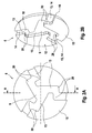
- FIG. 1 shows a housing wall 1 of a housing 2 with an aperture 4 formed as an opening 3.
- the opening 3 connects the interior of the housing 2 with the surroundings of the housing 2.
- a pressure compensation device 6 with a semipermeable membrane 7 and a membrane covering the protective device 8 is arranged on the outside 5 of Housing wall 1 is above the opening 3, a pressure compensation device 6 with a semipermeable membrane 7 and a membrane covering the protective device 8 is arranged.
- the protective device 8 covering the membrane 7 forms above the membrane 7 an intermediate space 9 which communicates with the ambient air via three ventilation paths 10, of which only one ventilation path is shown in the sectional representation of FIG.
- the illustration of the protective device 8 of FIG. 1 is a representation along the section line AA shown in FIG. 2A.
- the protective device 8 of Figure 1 and Figures 2A and 2B is designed as a protective plate 11, in which the ventilation paths 10 are formed on the diaphragm 7 facing the inner side 12 of the protective plate 11 as recesses 13. As FIG. 2B clearly shows, these recesses 13 are groove-like channels 14. The remaining surface of the inner side 12 is the attachment surface 15, with which the protective device 8 is fastened directly on the housing 2.
- a protective cap 16 is formed.
- the protective cap 16 has a cover part 17 and at least one side part 18, whereby the protective cap 16 forms the intermediate space 9 on direct mounting on the housing 2 itself.
- FIGS. 2A and 3B show two views of the protective device 8 of FIG. 1.
- FIG. 2A shows a view "from below" of the inner side 12 of the protective device 8 with depressions 13.
- the part of the recesses 13 which forms the gap 9.
- From this part of the recess 13 go from three groove-like channels 14 which extend from the gap 9 to the outer edge 19 of the side part 18.
- These groove-like channels form angularly extending ventilation paths 10, which have a cranked course in the specific embodiment. Overall, the ventilation paths 10 are designed to run labyrinth-like.
- FIG. 2B shows the protective device 8 in a further illustration, which makes the recesses 13 or groove-like channels 14 better visible.
- the on the opening. 3 attached membrane 7 ensures a pressure equalization of the interior of the housing 2 with the ambient air of the housing 2.
- gases such as air or water vapor can pass through the semipermeable membrane 7, while the membrane 7 is a barrier for liquids such as water.
- the protective device 8 covering the membrane 7 is arranged above the membrane 7 on the housing 2.
- the membrane 7 is optimally protected even before the pressure of a liquid jet such as the water jet of a high-pressure cleaner, the ventilation paths 10 are formed in the protective device 8 angularly extending.
- the membrane 7 communicates with the ambient air of the pressure compensation device 6 in connection, but protects against direct access from the outside to the membrane 7.
- penetrating liquid jet is not by the angular course of the ventilation path 10 directed or guided in the direction of the membrane 7.
- the angular configuration creates a dynamic pressure in the region of the angle 20, which prevents the targeted force of the water jet. Due to the bent course of the ventilation paths 10 with multiple angles 20, this effect is ensured even at short distances between the outer edge 19 of the protective device 8 to the space 9.
- the labyrinthine design of the ventilation paths 10 ensures that a pressure equalization is ensured even by penetrated liquid in one of the ventilation paths 10.
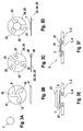
- FIGS 3A to 3F show the structure and the assembly of a pressure compensation device 6 according to the invention according to a second embodiment.
- the protective device 8 has a protective cap-like cover 21 and an intermediate element 22, which is designed as a holder for the cover 21.
- the intermediate element 22 between the cover 21 and the housing 2 is arranged.
- the ventilation paths 10 are formed as groove-like channels 14 in the cover 21, wherein the intermediate element 22 each having a recess 23 along the formed in the cover 21 ventilation paths 10 and the gap 9.
- the intermediate element 22 is designed as a holder 24 for the cover 21 and the membrane 7. That's it Intermediate member 22, a double-sided adhesive carrier 25 with two adhesive surfaces 26 formed on the top and bottom of the carrier 25.
- FIG. 3A shows the membrane 7, FIG.
- FIGS. 3D to 3F show the assembly and the FIGS Assembly of the pressure compensation device 6.
- the semi-permeable membrane 7 is glued to the top of the intermediate element 22 on the corresponding recess 23 ( Figure 3D).
- the carrier element 25 formed as intermediate element 22 is glued to the housing 2 via the opening 3, so that the semi-permeable membrane 7 is disposed directly above the opening 3.
- the cover 21 is glued on the upper side of the intermediate element 22 in such a way that the recesses 23 of the carrier 25 extend along the ventilation paths 10 formed in the cover 21.
- FIG. 3F shows the fully assembled pressure compensation device 6 on the housing 2 of a control device 27 of a motor vehicle.
Landscapes
- Engineering & Computer Science (AREA)
- Microelectronics & Electronic Packaging (AREA)
- Casings For Electric Apparatus (AREA)
- Separation Using Semi-Permeable Membranes (AREA)
Applications Claiming Priority (1)
| Application Number | Priority Date | Filing Date | Title |
|---|---|---|---|
| DE102006053111A DE102006053111A1 (de) | 2006-11-10 | 2006-11-10 | Druckausgleichsvorrichtung für ein Gehäuse |
Publications (3)
| Publication Number | Publication Date |
|---|---|
| EP1921906A2 true EP1921906A2 (fr) | 2008-05-14 |
| EP1921906A3 EP1921906A3 (fr) | 2010-04-28 |
| EP1921906B1 EP1921906B1 (fr) | 2019-12-11 |
Family
ID=39052696
Family Applications (1)
| Application Number | Title | Priority Date | Filing Date |
|---|---|---|---|
| EP07118227.3A Not-in-force EP1921906B1 (fr) | 2006-11-10 | 2007-10-10 | Dispositif d'équilibrage de pression pour un boîtier |
Country Status (2)
| Country | Link |
|---|---|
| EP (1) | EP1921906B1 (fr) |
| DE (1) | DE102006053111A1 (fr) |
Cited By (2)
| Publication number | Priority date | Publication date | Assignee | Title |
|---|---|---|---|---|
| GB2483275A (en) * | 2010-09-02 | 2012-03-07 | Warmup Plc | Housing with air vents that resists water ingress and suitable for an electronic controller |
| WO2016096421A3 (fr) * | 2014-12-19 | 2016-08-11 | Robert Bosch Gmbh | Dispositif de protection pour un élément d'équilibrage de pression |
Families Citing this family (10)
| Publication number | Priority date | Publication date | Assignee | Title |
|---|---|---|---|---|
| DE102011086108A1 (de) | 2011-11-10 | 2013-05-16 | Zf Friedrichshafen Ag | Druckausgleichsvorrichtung, Gehäuse und Verfahren zum Herstellen einer Druckausgleichsvorrichtung |
| US9769951B2 (en) | 2015-07-08 | 2017-09-19 | Autoliv Asp, Inc. | Automotive radar system and automotive radar sensor module with breather structure |
| DE102017122957A1 (de) * | 2017-10-04 | 2019-04-04 | R. Stahl Schaltgeräte GmbH | Geschweißte Druckentlastungsvorrichtung |
| CN110832716B (zh) | 2017-06-01 | 2022-04-29 | R.施塔尔开关设备有限责任公司 | 焊接的卸压装置 |
| DE102017123078B4 (de) * | 2017-10-05 | 2019-10-31 | Hugo Benzing Gmbh & Co. Kg | Druckausgleichseinheit und Baueinheit aus einem Gehäuse und einer Druckausgleichseinheit |
| DE102019201103A1 (de) * | 2019-01-29 | 2020-07-30 | Lufthansa Technik Aktiengesellschaft | Anbaugehäuse zur Befestigung an einem Luftfahrzeug |
| DE202019005304U1 (de) * | 2019-02-25 | 2020-02-26 | Nidec Motors & Actuators (Germany) Gmbh | Pumpeinheit aufweisend einen Steckverbinder mit Sinterfilter zum Druckausgleich |
| DE202019005305U1 (de) | 2019-02-25 | 2020-02-26 | Nidec Motors & Actuators (Germany) Gmbh | Pumpeinheit aufweisend einen Steckverbinder mit Druckausgleichselement |
| DE102020134163A1 (de) | 2020-12-18 | 2022-06-23 | Schreiner Group Gmbh & Co. Kg | Schutzkappe und Verfahren zum Herstellen einer Schutzkappe für ein Druckausgleichselement und System |
| DE102023211941A1 (de) | 2023-11-29 | 2025-06-05 | Robert Bosch Gesellschaft mit beschränkter Haftung | Gehäuseelement und elektrische Vorrichtung |
Family Cites Families (6)
| Publication number | Priority date | Publication date | Assignee | Title |
|---|---|---|---|---|
| DE19544974C1 (de) * | 1995-12-01 | 1997-05-22 | Siemens Ag | Steuergerät, insbesondere zur Auslösung eines Rückhaltemittels in einem Fahrzeug |
| GB2330952A (en) * | 1997-11-01 | 1999-05-05 | Motorola Ltd | Sealing arrangement for an electronic circuit module |
| KR100561795B1 (ko) * | 1997-11-28 | 2006-03-21 | 지멘스 악티엔게젤샤프트 | 전기 제어 장치용 통풍 장치 |
| DE102004056662A1 (de) * | 2004-11-24 | 2006-06-01 | Robert Bosch Gmbh | Elektrisches Gerät |
| DE202005018557U1 (de) * | 2005-09-22 | 2006-07-20 | Hidde, Axel R., Dr. Ing. | Druckausgleichsverschraubung kleinen Bauvolumens und großer Membranfläche mit Innenanschlag |
| DE202005014946U1 (de) * | 2005-09-22 | 2006-01-19 | Hidde, Axel R., Dr.-Ing. | Druckausgleichsverschraubung |
-
2006
- 2006-11-10 DE DE102006053111A patent/DE102006053111A1/de not_active Withdrawn
-
2007
- 2007-10-10 EP EP07118227.3A patent/EP1921906B1/fr not_active Not-in-force
Cited By (2)
| Publication number | Priority date | Publication date | Assignee | Title |
|---|---|---|---|---|
| GB2483275A (en) * | 2010-09-02 | 2012-03-07 | Warmup Plc | Housing with air vents that resists water ingress and suitable for an electronic controller |
| WO2016096421A3 (fr) * | 2014-12-19 | 2016-08-11 | Robert Bosch Gmbh | Dispositif de protection pour un élément d'équilibrage de pression |
Also Published As
| Publication number | Publication date |
|---|---|
| DE102006053111A1 (de) | 2008-05-15 |
| EP1921906A3 (fr) | 2010-04-28 |
| EP1921906B1 (fr) | 2019-12-11 |
Similar Documents
| Publication | Publication Date | Title |
|---|---|---|
| EP1921906B1 (fr) | Dispositif d'équilibrage de pression pour un boîtier | |
| DE102011075260B4 (de) | MEMS-Mikrofon | |
| DE4217837B4 (de) | Hermetisch abgeschlossenes Gehäuse | |
| EP1034692B1 (fr) | Dispositif de ventilation, notamment pour appareils de commande electriques | |
| DE112015003942T5 (de) | Vorrichtung zur Befestigung eines Aufpralldrucksensors auf einer trockenen Seite | |
| EP0779170B1 (fr) | Détecteur d'agents polluants | |
| DE102006035607B4 (de) | Sensorbefestigungsstruktur und Ultraschallfühler | |
| DE102012112098A1 (de) | Anordnung zum Druckausgleich eines Gehäuses | |
| DE102020212123A1 (de) | Sensor und Verfahren zur Herstellung eines Sensors | |
| DE102009003149A1 (de) | Druckausgleichseinheit zur Verwendung in einem Drucksensor | |
| EP1979709A1 (fr) | Systeme a sondes d'inertie | |
| DE102014225861A1 (de) | Sensoreinrichtung, insbesondere für die Verwendung in einem Kraftfahrzeug | |
| DE102010063423A1 (de) | Druckausgleichselement, Batterie mit Druckausgleichselement und Kraftfahrzeug mit einer entsprechenden Batterie | |
| DE102020134548A1 (de) | Notentgasungsvorrichtung | |
| DE102015214923A1 (de) | Druckausgleichselement und Gehäuse mit einem solchen | |
| DE102017123078A1 (de) | Druckausgleichseinheit und Baueinheit aus einem Gehäuse und einer Druckausgleichseinheit | |
| DE102013206140A1 (de) | Gassackmodulanordnung für ein Kraftfahrzeug | |
| DE102011012682A1 (de) | Gassensor, insbesondere füe automobile Anwendungen | |
| DE102005052929B4 (de) | Sensor für ein Luftfahrzeug, insbesondere ein Flugzeug oder Hubschrauber | |
| DE102019131152A1 (de) | Batteriegehäuse | |
| DE102006058301B4 (de) | Luftdrucksensor für eine Seitenaufprallerkennung | |
| WO2011117140A1 (fr) | Éléments d'équilibrage de pression pour boîtier isolé de l'environnement extérieur, et boîtier correspondant | |
| DE102007026446A1 (de) | Schnell montierbares Sensorgehäuse für Sensoren mit Luftkontakt | |
| DE102021114834A1 (de) | Gehäuse für ein elektronisches Steuergerät | |
| DE10333964A1 (de) | Deckel für das Gehäuse einer Sensorbaugruppe mit einem Drucksensor |
Legal Events
| Date | Code | Title | Description |
|---|---|---|---|
| PUAI | Public reference made under article 153(3) epc to a published international application that has entered the european phase |
Free format text: ORIGINAL CODE: 0009012 |
|
| AK | Designated contracting states |
Kind code of ref document: A2 Designated state(s): AT BE BG CH CY CZ DE DK EE ES FI FR GB GR HU IE IS IT LI LT LU LV MC MT NL PL PT RO SE SI SK TR |
|
| AX | Request for extension of the european patent |
Extension state: AL BA HR MK RS |
|
| PUAL | Search report despatched |
Free format text: ORIGINAL CODE: 0009013 |
|
| AK | Designated contracting states |
Kind code of ref document: A3 Designated state(s): AT BE BG CH CY CZ DE DK EE ES FI FR GB GR HU IE IS IT LI LT LU LV MC MT NL PL PT RO SE SI SK TR |
|
| AX | Request for extension of the european patent |
Extension state: AL BA HR MK RS |
|
| 17P | Request for examination filed |
Effective date: 20101028 |
|
| 17Q | First examination report despatched |
Effective date: 20101125 |
|
| AKX | Designation fees paid |
Designated state(s): DE FR GB IT |
|
| GRAP | Despatch of communication of intention to grant a patent |
Free format text: ORIGINAL CODE: EPIDOSNIGR1 |
|
| INTG | Intention to grant announced |
Effective date: 20190607 |
|
| GRAS | Grant fee paid |
Free format text: ORIGINAL CODE: EPIDOSNIGR3 |
|
| GRAA | (expected) grant |
Free format text: ORIGINAL CODE: 0009210 |
|
| AK | Designated contracting states |
Kind code of ref document: B1 Designated state(s): DE FR GB IT |
|
| REG | Reference to a national code |
Ref country code: GB Ref legal event code: FG4D Free format text: NOT ENGLISH |
|
| REG | Reference to a national code |
Ref country code: DE Ref legal event code: R096 Ref document number: 502007016817 Country of ref document: DE |
|
| RAP2 | Party data changed (patent owner data changed or rights of a patent transferred) |
Owner name: ROBERT BOSCH GMBH |
|
| REG | Reference to a national code |
Ref country code: DE Ref legal event code: R097 Ref document number: 502007016817 Country of ref document: DE |
|
| PLBE | No opposition filed within time limit |
Free format text: ORIGINAL CODE: 0009261 |
|
| STAA | Information on the status of an ep patent application or granted ep patent |
Free format text: STATUS: NO OPPOSITION FILED WITHIN TIME LIMIT |
|
| 26N | No opposition filed |
Effective date: 20200914 |
|
| GBPC | Gb: european patent ceased through non-payment of renewal fee |
Effective date: 20201010 |
|
| PG25 | Lapsed in a contracting state [announced via postgrant information from national office to epo] |
Ref country code: GB Free format text: LAPSE BECAUSE OF NON-PAYMENT OF DUE FEES Effective date: 20201010 |
|
| PGFP | Annual fee paid to national office [announced via postgrant information from national office to epo] |
Ref country code: DE Payment date: 20211214 Year of fee payment: 15 |
|
| PGFP | Annual fee paid to national office [announced via postgrant information from national office to epo] |
Ref country code: IT Payment date: 20211029 Year of fee payment: 15 Ref country code: FR Payment date: 20211022 Year of fee payment: 15 |
|
| REG | Reference to a national code |
Ref country code: DE Ref legal event code: R119 Ref document number: 502007016817 Country of ref document: DE |
|
| PG25 | Lapsed in a contracting state [announced via postgrant information from national office to epo] |
Ref country code: FR Free format text: LAPSE BECAUSE OF NON-PAYMENT OF DUE FEES Effective date: 20221031 Ref country code: DE Free format text: LAPSE BECAUSE OF NON-PAYMENT OF DUE FEES Effective date: 20230503 |
|
| PG25 | Lapsed in a contracting state [announced via postgrant information from national office to epo] |
Ref country code: IT Free format text: LAPSE BECAUSE OF NON-PAYMENT OF DUE FEES Effective date: 20221010 |