EP1922455B1 - Panneau destiné à être connecté mécaniquement à un autre panneau par rotation - Google Patents
Panneau destiné à être connecté mécaniquement à un autre panneau par rotation Download PDFInfo
- Publication number
- EP1922455B1 EP1922455B1 EP06777158.4A EP06777158A EP1922455B1 EP 1922455 B1 EP1922455 B1 EP 1922455B1 EP 06777158 A EP06777158 A EP 06777158A EP 1922455 B1 EP1922455 B1 EP 1922455B1
- Authority
- EP
- European Patent Office
- Prior art keywords
- panel
- groove
- profile
- cheek
- locking
- Prior art date
- Legal status (The legal status is an assumption and is not a legal conclusion. Google has not performed a legal analysis and makes no representation as to the accuracy of the status listed.)
- Active
Links
Images

Classifications
-
- E—FIXED CONSTRUCTIONS
- E04—BUILDING
- E04F—FINISHING WORK ON BUILDINGS, e.g. STAIRS, FLOORS
- E04F13/00—Coverings or linings, e.g. for walls or ceilings
- E04F13/07—Coverings or linings, e.g. for walls or ceilings composed of covering or lining elements; Sub-structures therefor; Fastening means therefor
- E04F13/08—Coverings or linings, e.g. for walls or ceilings composed of covering or lining elements; Sub-structures therefor; Fastening means therefor composed of a plurality of similar covering or lining elements
-
- E—FIXED CONSTRUCTIONS
- E04—BUILDING
- E04F—FINISHING WORK ON BUILDINGS, e.g. STAIRS, FLOORS
- E04F15/00—Flooring
- E04F15/02—Flooring or floor layers composed of a number of similar elements
-
- E—FIXED CONSTRUCTIONS
- E04—BUILDING
- E04F—FINISHING WORK ON BUILDINGS, e.g. STAIRS, FLOORS
- E04F2201/00—Joining sheets or plates or panels
- E04F2201/01—Joining sheets, plates or panels with edges in abutting relationship
- E04F2201/0153—Joining sheets, plates or panels with edges in abutting relationship by rotating the sheets, plates or panels around an axis which is parallel to the abutting edges, possibly combined with a sliding movement
-
- E—FIXED CONSTRUCTIONS
- E04—BUILDING
- E04F—FINISHING WORK ON BUILDINGS, e.g. STAIRS, FLOORS
- E04F2201/00—Joining sheets or plates or panels
- E04F2201/02—Non-undercut connections, e.g. tongue and groove connections
- E04F2201/027—Non-undercut connections, e.g. tongue and groove connections connected by tongues and grooves, the centerline of the connection being inclined to the top surface
-
- F—MECHANICAL ENGINEERING; LIGHTING; HEATING; WEAPONS; BLASTING
- F16—ENGINEERING ELEMENTS AND UNITS; GENERAL MEASURES FOR PRODUCING AND MAINTAINING EFFECTIVE FUNCTIONING OF MACHINES OR INSTALLATIONS; THERMAL INSULATION IN GENERAL
- F16B—DEVICES FOR FASTENING OR SECURING CONSTRUCTIONAL ELEMENTS OR MACHINE PARTS TOGETHER, e.g. NAILS, BOLTS, CIRCLIPS, CLAMPS, CLIPS OR WEDGES; JOINTS OR JOINTING
- F16B2200/00—Constructional details of connections not covered for in other groups of this subclass
- F16B2200/30—Dovetail-like connections
-
- Y—GENERAL TAGGING OF NEW TECHNOLOGICAL DEVELOPMENTS; GENERAL TAGGING OF CROSS-SECTIONAL TECHNOLOGIES SPANNING OVER SEVERAL SECTIONS OF THE IPC; TECHNICAL SUBJECTS COVERED BY FORMER USPC CROSS-REFERENCE ART COLLECTIONS [XRACs] AND DIGESTS
- Y10—TECHNICAL SUBJECTS COVERED BY FORMER USPC
- Y10T—TECHNICAL SUBJECTS COVERED BY FORMER US CLASSIFICATION
- Y10T403/00—Joints and connections
- Y10T403/55—Member ends joined by inserted section
-
- Y—GENERAL TAGGING OF NEW TECHNOLOGICAL DEVELOPMENTS; GENERAL TAGGING OF CROSS-SECTIONAL TECHNOLOGIES SPANNING OVER SEVERAL SECTIONS OF THE IPC; TECHNICAL SUBJECTS COVERED BY FORMER USPC CROSS-REFERENCE ART COLLECTIONS [XRACs] AND DIGESTS
- Y10—TECHNICAL SUBJECTS COVERED BY FORMER USPC
- Y10T—TECHNICAL SUBJECTS COVERED BY FORMER US CLASSIFICATION
- Y10T403/00—Joints and connections
- Y10T403/55—Member ends joined by inserted section
- Y10T403/553—Laterally inserted section
-
- Y—GENERAL TAGGING OF NEW TECHNOLOGICAL DEVELOPMENTS; GENERAL TAGGING OF CROSS-SECTIONAL TECHNOLOGIES SPANNING OVER SEVERAL SECTIONS OF THE IPC; TECHNICAL SUBJECTS COVERED BY FORMER USPC CROSS-REFERENCE ART COLLECTIONS [XRACs] AND DIGESTS
- Y10—TECHNICAL SUBJECTS COVERED BY FORMER USPC
- Y10T—TECHNICAL SUBJECTS COVERED BY FORMER US CLASSIFICATION
- Y10T403/00—Joints and connections
- Y10T403/55—Member ends joined by inserted section
- Y10T403/559—Fluted or splined section
-
- Y—GENERAL TAGGING OF NEW TECHNOLOGICAL DEVELOPMENTS; GENERAL TAGGING OF CROSS-SECTIONAL TECHNOLOGIES SPANNING OVER SEVERAL SECTIONS OF THE IPC; TECHNICAL SUBJECTS COVERED BY FORMER USPC CROSS-REFERENCE ART COLLECTIONS [XRACs] AND DIGESTS
- Y10—TECHNICAL SUBJECTS COVERED BY FORMER USPC
- Y10T—TECHNICAL SUBJECTS COVERED BY FORMER US CLASSIFICATION
- Y10T403/00—Joints and connections
- Y10T403/70—Interfitted members
- Y10T403/7045—Interdigitated ends
Definitions
- the invention relates to a panel made of wood or wood material, for connection to other similar panels, in particular for the production of wall, ceiling or floor surfaces.
- Such panels are known. They have at least two profiled edges, a first edge is provided with a groove profile, a second edge with a corresponding spring profile. Tongue and groove profile define two panels at the same height.
- the panels have locking means which fix two panels in the same plane, thus preventing disengagement of the panels. Moving the panels parallel to each other is usually still possible.
- the thus prepared panels are offered according to a first embodiment as so-called "click-panels" with a profile that is designed as a latching connection.
- a second embodiment which is the subject of the present invention, such panels are joined together by pivoting.
- WO 2004/079 130 discloses a panel with a tongue and groove profile, the lower groove cheek has a greater thickness at the free end than in the area under the free end of the upper groove cheek.
- the panel according to the invention has known features with regard to the tongue and groove profile and the locking means. It is prepared for mechanical connection with at least one other, similar panel by pivoting.
- the tongue and groove profile is used to set the panels at the same height to each other.
- the groove profile has a short groove cheek, a groove base and a long groove cheek on at least one side of the panel, wherein the long groove cheek has a greater thickness at its free end than in the region of the groove bottom.
- a corresponding with the groove profile spring profile is formed on at least one other side of the panel, tongue and groove in the assembled state each have upper contact surfaces which are inclined to the surface of the panel and lower contact surfaces, which are rounded.
- the locking means serve to fix the panels in the same plane to each other. They have a locking surface on the spring and a locking surface on the groove, wherein the locking surfaces are arranged on the groove and on the spring between the surfaces of the panel at the level of the groove bottom.
- the surfaces of the panel are the top and the bottom of the panel, the profiles and locking means are respectively attached to narrow sides of the panel.
- the essential measure for avoiding damage to the panel during laying, in particular for avoiding gaps in the region of the groove base, is to form tongue and groove in the area of the contact surfaces in a form-fitting manner, but not by clamping.
- the finding on which the invention builds, shows that tongue and groove define the profile only in terms of determining the height of the panels to each other. It is disadvantageous if tongue and groove engage in a clamping, because due to the tendency to split and the determination of the height is not accurate. It is quite sufficient if tongue and groove mesh with each other without deformation.
- the height H of the locking surfaces is not more than 20% of the maximum height M of the long groove cheek. It has been found by experiments that a profile with low height of the backup surfaces is particularly economical to produce. It should be noted as a particular advantage that at low height of the locking surfaces a slight tendency to split the panel is observed. Relative to the maximum height M of the long Nutwange the height H of the locking surface according to the invention is not more than 15%, preferably not more than 12%. This is to form the locking means only little material from the long groove cheek -and correspondingly also from the spring-side profile - remove. This saves tool and allows a stable profile, because the free end of the long groove cheek is dimensioned according to the inventively lower material loss larger than before.
- the top of the long groove cheek is at least partially disposed obliquely in sections relative to the top of the panel. It has proved to be advantageous if the top of the long groove cheek is at least partially executed at an angle ⁇ , which is shallower than the angle ⁇ .
- the angle ⁇ is in particular smaller than 10 °, it is preferably up to 7 °, particularly preferably up to 5 °. Generally speaking, the angle ⁇ according to the invention is about half as large as the angle ⁇ .
- a further advantageous measure, with which a splitting of the joined panels or a gap in the joining of the panels is prevented, is the provision of free spaces between the free end of the long groove cheek and the spring with the exception of the securing surfaces.
- a first space is provided on the one hand between the spring and lower groove cheek. It extends from the lower contact surface to the backup surface. The free space serves on the one hand to pick up dust and impurities that can not be caught during installation. On the other hand, manufacturing deviations in the production of the profile are compensated.
- a second clearance adjoins the upper end of the locking surfaces and extends between the panel provided with the groove profile and the panel provided with the spring profile. Again, there is room to pick up impurities.
- the free space also ensures that controlled and calculable conditions arise in two joined panels, which are in contact only in the area of the contact surfaces and the locking surfaces.
- the angle between the locking surface of the groove profile and the surface of the groove cheek adjoining the groove base on this securing surface is as small as possible, as a rule selected by 90 °, in the case of known profiles. This is because those skilled in the art believe that the pull-out resistance is particularly high, or that such a steep locking surface is required to ensure effective tongue-and-groove locking. It will, however proposed that the angle ⁇ is at least 125 °, preferably 130 °, particularly preferably 135 °. In this area, it is not possible to pull pasted panels together in the plane in which they are laid.
- the pull-out resistance is optimized by the fact that the inclination of the wood or wood-based material in this part of the profile under tensile stress to split, is minimized by the large angle ⁇ .
- angle ⁇ which spans between a connection from the upper end of the locking surface on the groove profile to the end of the surface of the groove profile on the panel on the one hand and the extension of the locking surface on the groove profile on the other hand, with at least 90 ° to be measured. It has surprisingly been found in experiments that such a large angle ⁇ , which can easily extend to 95 ° or up to 105 °, nevertheless ensures effective locking.
- An essential measure for tool-saving machining of a profile with a low height of the locking surfaces is that the contact surface on the short groove cheek and a surface portion which delimits the free end of the long groove cheek toward the top of the panel are both arranged obliquely to the top of the panel. Preferably, further portions of the upper side of the long groove cheek are arranged obliquely to the top of the panel.
- a tool is sufficient, usually a milling cutter, to work out the groove base and possibly the top of the long groove cheek.
- two tools are required, as it was not possible to feed the tool linearly into the base of the groove and from there to the shoulder of the locking surface.
- the contact surface on the short groove cheek and a surface portion at the free end of the long groove cheek, which is inclined to the groove base are arranged at an angle ⁇ of at least 5 °, preferably at least 10 °, more preferably at least 20 ° to the top of the panel.
- This design of the contact surface on the short groove cheek-and thus usually the corresponding contact surface on the spring and the surface portion at the free end of the long groove cheek, which is inclined to the groove bottom, at an angle ⁇ of at least 5 °, but preferably of more than 5 °, allows tool-saving finishing of the profile.
- the tool insert is reduced in that fewer tools are required for producing the profile than in known profiles that these tools also have to remove less material, thereby minimizing the wear on the tools.
- a profile according to the invention may have two narrow sides with groove profile and two sides with spring profile in a four-sided profile.
- Such panels can be prepared completely ready for laying by factory molding of the profile.
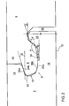
- Fig. 1 shows a panel 2 made of high density fiberboard (HDF) with a groove profile 6 at a narrow side 5.
- the panel can also be made of solid wood.
- the panel 2 is engaged with a second panel 4, which has a corresponding spring profile 8 on a narrow side 7.
- the groove profile 6 is formed between the top 10 and the bottom 12 of the panel in a narrow side 5 of the high-density fiberboard, as well as the spring profile 8 on the narrow side 7 of the panel. 4
- the groove profile 6 has a short groove cheek 14, a groove base 16 and a long groove cheek 18.
- the groove base 16 is designed with a base 17, which merges into the groove cheeks 14 and 18 in a rounded shape to avoid notch stresses and the tendency to fission Add panels 2 and 4 to minimize.
- the long groove cheek 18 extends from the bottom of the groove to a free end 20, which is no longer covered by the short groove cheek 14.
- the free end 20 of the long groove cheek 18 has a greater height M than in the region lying below the free end of the short groove cheek 14, and the in Fig. 1 is marked as height m.
- groove profile 6 and spring profile 8 In the joined state, as in Fig. 1 shown, groove profile 6 and spring profile 8 upper abutment surfaces 24a, 24b, which are relative to the top 10- inclined. Lower contact surfaces 26a, 26b are made rounded, which facilitates the insertion of the spring into the groove.
- a locking surface 28a can be arranged in the region of this rise.
- a corresponding locking surface 28b is mounted in the region of the spring profile 8.
- the height H of these locking surfaces 28a, 28b-related to the height M of the free end 20- is in the profile according to Fig.1 14%.
- the locking surfaces 28a, 28b are arranged between the upper side 10 and lower side 12 of the panels 2, 4 in the height of the groove bottom 16.
- the locking surfaces 28a, 28b are aligned such that an extension of the locking surfaces 28a, 28b with a connecting line V, which forms an angle ⁇ of 90 ° from the top 10 of the panel 2 at the base of the groove profile 6 to the upper end of the locking surface 28 a , Next forms the locking surface 28 a with the Top 30 of the long groove cheek 18 an angle ⁇ of 135 °.
- a free space 34 which is bounded by the top 30 of the long groove cheek 18 and by the bottom 32 of the spring profile 8.
- a free space 36 extends between the upper end of the locking surfaces 28a, 28b, the spring profile 8 and the bottom 12 of the panels 2, 4, a free space 36 extends.
- Fig. 1 further shows a feature of the groove profile that allows the tool-saving working out of a profile with low height of the locking surfaces.
- the contact surface 24a on the short groove cheek and a surface portion 38 which limits the free end 20 of the long groove cheek toward the top 10 of the panel 2 are both arranged at an angle ⁇ of 15 ° obliquely to the top 10 of the panel 2.
- the top 30 of the long groove cheek 18 and the bottom 32 of the spring are inclined relative to the top 10 of the panel. They are worked out at a smaller angle than the angle ⁇ .
- the angle ⁇ (see Fig. 2 ) of 7 ° is about half as large as the angle ⁇ according to this preferred embodiment.
- a tool usually a milling cutter, to work out the groove base 16 and possibly the upper side 30 of the long groove cheek 18 is sufficient.
- a tool usually a milling cutter, to work out the groove base 16 and possibly the upper side 30 of the long groove cheek 18 is sufficient.
- two tools are required because a linear feeding a single tool into the groove base 16 and from there to the approach of the locking surface 28a was not possible.
- Fig. 2 shows a profile made of spruce wood. Same reference numerals as in Fig.1 also denote the same features.
- the profile of spruce wood can be made directly and exclusively from solid wood. It is usual, however, that the spruce wood is used as a core material, wherein the top layer of other wood veneer, cork, linoleum or the like can exist.
- the underside of the solid wood profile can be coated with a solid paper that absorbs deformation forces.
- a footfall sound insulation made of plastic, cork or felt can be applied to the underside of the profile.
- the angle ⁇ is 15 °.
- the angle ⁇ is 133 °.
- the angle ⁇ is 7 °.
- Free spaces 34 and 36 each extend on both sides of the locking surfaces 28a, 28b.
- Further free spaces 40 and 42 each extend on both sides of the upper abutment surfaces 24a, 24b.
- the lower abutment surfaces 26a, 26b are adjacent to clearances 42 and 34.
- the profile according to the invention according to claim 2 requires only a small use of tools. On the one hand, few tools are used, because in particular the groove base can be formed in one operation with a tool. On the other hand, the profile requires a low material removal due to the flat design. As a result, the tools are little stressed and the wear is correspondingly low. Prolonged life and low intervention in the production of changing the tools are the result.
Landscapes
- Engineering & Computer Science (AREA)
- Architecture (AREA)
- Civil Engineering (AREA)
- Structural Engineering (AREA)
- Finishing Walls (AREA)
- Joining Of Building Structures In Genera (AREA)
- Floor Finish (AREA)
Claims (3)
- Panneau préparé à être connecté mécaniquement à au moins un autre panneau similaire par rotation, avec- un profilé à rainure et ressort (6, 8) pour l'assemblage par complémentarité de forme mais sans serrage du panneau (2, 4) avec l'autre panneau à la même hauteur l'un par rapport à l'autre, présentant un profilé à rainure (6) avec une joue de rainure courte (14), un fond de rainure (16) et une joue de rainure longue (18) sur au moins un côté du panneau, et un profilé à ressort (8) correspondant au profilé à rainure (6) sur au moins un autre côté du panneau, dans lequel la joue de rainure longue (18) présente une épaisseur plus importante à son extrémité libre (20) que dans la région située en-dessous de l'extrémité libre de la joue de rainure courte (14), et dans lequel, lorsque les deux panneaux sont assemblés, la rainure et le ressort respectivement présentent des surfaces de contact supérieures (24a, 24b) inclinées vers la surface supérieure (10) du panneau (2, 4) et des surfaces de contact inférieures (26a, 26b) arrondies, et avec- des moyens de blocage (28a, 28b) pour la fixation du panneau (2, 4) avec l'autre panneau sur un même plan l'un par rapport à l'autre, présentant une surface de blocage (28b) sur le ressort et une surface de blocage (28a) sur la rainure, les surfaces de blocage (28a, b) sur la rainure et sur le ressort étant agencées entre les surfaces (10, 12) des panneaux (2, 4) à la hauteur du fond de rainure (16), caractérisé en ce que la hauteur des surfaces de blocage (28a, 28b) ne dépasse pas 20% de la hauteur maximale de la joue de rainure longue (18),- au moins la surface de contact supérieure (24a) de la rainure et la section de surface (38) tournée vers le fond de rainure (16) à l'extrémité libre (20) de la joue de rainure longue (18) sont disposées en biais par rapport à la surface supérieure (10) du panneau (2), sous un angle δ, et- au moins des sections du côté supérieur (30) de la joue de rainure longue (18) sont agencées sous un angle ε par rapport à la surface supérieure du panneau mesurant environ la moitié de l'angle δ.
- Panneau selon la revendication 1, caractérisé en ce que l'angle ε mesure jusqu'à 10°, de préférence jusqu'à 7° et de manière particulièrement préférée jusqu'à 5° par rapport à la surface supérieure (10) du panneau (2).
- Panneau selon la revendication 1, caractérisé en ce que dans l'état assemblé de deux panneaux, à l'exception des surfaces de blocage (28a, 28b), il est prévu des espaces libres (34, 36) entre l'extrémité libre (20) de la joue de rainure longue (18) et le ressort.
Applications Claiming Priority (2)
| Application Number | Priority Date | Filing Date | Title |
|---|---|---|---|
| DE202005014132U DE202005014132U1 (de) | 2005-09-07 | 2005-09-07 | Paneel aus Holz |
| PCT/EP2006/008604 WO2007028560A1 (fr) | 2005-09-07 | 2006-09-04 | Panneau destine a etre connecte mecaniquement a un autre panneau par pivotement |
Publications (2)
| Publication Number | Publication Date |
|---|---|
| EP1922455A1 EP1922455A1 (fr) | 2008-05-21 |
| EP1922455B1 true EP1922455B1 (fr) | 2014-12-31 |
Family
ID=37433778
Family Applications (1)
| Application Number | Title | Priority Date | Filing Date |
|---|---|---|---|
| EP06777158.4A Active EP1922455B1 (fr) | 2005-09-07 | 2006-09-04 | Panneau destiné à être connecté mécaniquement à un autre panneau par rotation |
Country Status (6)
| Country | Link |
|---|---|
| US (1) | US8978335B2 (fr) |
| EP (1) | EP1922455B1 (fr) |
| CA (1) | CA2622019A1 (fr) |
| DE (1) | DE202005014132U1 (fr) |
| ES (1) | ES2533006T3 (fr) |
| WO (1) | WO2007028560A1 (fr) |
Cited By (1)
| Publication number | Priority date | Publication date | Assignee | Title |
|---|---|---|---|---|
| CN112334624A (zh) * | 2018-06-15 | 2021-02-05 | 阿卡曾塔板材型材有限公司 | 嵌板 |
Families Citing this family (14)
| Publication number | Priority date | Publication date | Assignee | Title |
|---|---|---|---|---|
| DE102009019492A1 (de) * | 2009-05-04 | 2010-11-11 | Akzenta Paneele + Profile Gmbh | Verriegelungssystem für Paneele |
| CN102803625B (zh) | 2010-01-11 | 2014-12-31 | 韦林奇创新公司 | 具有互锁设计的地板覆盖物 |
| PL2423410T3 (pl) * | 2010-08-27 | 2013-07-31 | Barlinek Sa | Panel budowlany z ulepszonymi środkami ryglującymi do rozłącznego łączenia z panelami budowlanymi tego samego rodzaju |
| US20150110554A1 (en) * | 2013-10-22 | 2015-04-23 | Plastic Safety Systems, Inc. | Portable roadway warning device |
| FR3024990B1 (fr) | 2014-08-25 | 2018-11-16 | Gerflor | Panneau de sol pour la realisation d'un revetement. |
| EP4438834A3 (fr) | 2015-01-15 | 2025-01-08 | Unilin, BV | Panneau de plancher pour former un revêtement de sol |
| EP4722470A2 (fr) | 2015-01-16 | 2026-04-08 | Unilin, BV | Panneau de plancher pour former un revêtement de sol |
| EP3245354B1 (fr) * | 2015-01-16 | 2026-04-15 | Unilin BV | Panneau de plancher pour la formation d'un revêtement de sol |
| BE1022985B1 (nl) | 2015-01-16 | 2016-10-27 | Flooring Industries Limited Sarl | Vloerpaneel voor het vormen van een vloerbekleding |
| BE1023818B1 (nl) | 2016-01-15 | 2017-08-01 | Flooring Industries Limited Sarl | Vloerpaneel voor het vormen van een vloerbekleding |
| BE1027634B1 (nl) * | 2019-10-08 | 2021-05-06 | Flooring Ind Ltd Sarl | Vloerpaneel voor het vormen van een vloerbekleding |
| US12195964B2 (en) | 2020-08-24 | 2025-01-14 | Huber Engineered Woods Llc | Tongue-and-groove panel for improved interpanel fit |
| NL2026858B1 (en) * | 2020-11-09 | 2022-06-27 | I4F Licensing Nv | Decorative panel, and covering of such decorative panels |
| NL2028776B1 (en) * | 2021-07-19 | 2023-01-25 | I4F Licensing Nv | Multi-purpose tile system, tile covering, and tile |
Family Cites Families (11)
| Publication number | Priority date | Publication date | Assignee | Title |
|---|---|---|---|---|
| SE0001325L (sv) * | 2000-04-10 | 2001-06-25 | Valinge Aluminium Ab | Låssystem för hopfogning av golvskivor samt golvskivor försedda med sådana låssystem och golv bildat av sådana golvskivor |
| BE1010487A6 (nl) * | 1996-06-11 | 1998-10-06 | Unilin Beheer Bv | Vloerbekleding bestaande uit harde vloerpanelen en werkwijze voor het vervaardigen van dergelijke vloerpanelen. |
| DE50004151D1 (de) * | 1999-12-27 | 2003-11-27 | Kronospan Tech Co Ltd | Paneele mit Verbindungsmitteln |
| BE1013569A3 (nl) * | 2000-06-20 | 2002-04-02 | Unilin Beheer Bv | Vloerbekleding. |
| DE20109840U1 (de) * | 2001-06-17 | 2001-09-06 | Kronospan Technical Co. Ltd., Nikosia | Platten mit Einschiebe-Steckprofil |
| DE10138285A1 (de) * | 2001-08-10 | 2003-03-06 | Akzenta Paneele & Profile Gmbh | Paneel sowie Befestigungssystem für Paneele |
| DE10230818B3 (de) * | 2002-07-08 | 2004-03-04 | Kronotec Ag | Fussbodenpaneel und Verfahren zum Verlegen eines Fussbodenpaneels |
| DE50309830D1 (de) * | 2002-11-15 | 2008-06-26 | Flooring Technologies Ltd | Einrichtung bestehend aus zwei miteinander verbindbaren Bauplatten und einem Einsatz zum Verriegeln dieser Bauplatten |
| ATE557149T1 (de) | 2003-03-06 | 2012-05-15 | Vaelinge Innovation Ab | Bodenbelagsysteme und installationsverfahren |
| DE10313112B4 (de) * | 2003-03-24 | 2007-05-03 | Fritz Egger Gmbh & Co. | Belag mit einer Mehrzahl von Paneelen, insbesondere Fußbodenbelag, sowie Verfahren zum Verlegen von Paneelen |
| US7516588B2 (en) * | 2004-01-13 | 2009-04-14 | Valinge Aluminium Ab | Floor covering and locking systems |
-
2005
- 2005-09-07 DE DE202005014132U patent/DE202005014132U1/de not_active Expired - Lifetime
-
2006
- 2006-09-04 ES ES06777158.4T patent/ES2533006T3/es active Active
- 2006-09-04 US US12/066,115 patent/US8978335B2/en active Active
- 2006-09-04 CA CA002622019A patent/CA2622019A1/fr not_active Abandoned
- 2006-09-04 EP EP06777158.4A patent/EP1922455B1/fr active Active
- 2006-09-04 WO PCT/EP2006/008604 patent/WO2007028560A1/fr not_active Ceased
Cited By (3)
| Publication number | Priority date | Publication date | Assignee | Title |
|---|---|---|---|---|
| CN112334624A (zh) * | 2018-06-15 | 2021-02-05 | 阿卡曾塔板材型材有限公司 | 嵌板 |
| RU2754246C1 (ru) * | 2018-06-15 | 2021-08-31 | Акзента Панееле + Профайл Гмбх | Панель |
| US11591805B2 (en) | 2018-06-15 | 2023-02-28 | Akzenta Paneele + Profile Gmbh | Panel |
Also Published As
| Publication number | Publication date |
|---|---|
| WO2007028560A1 (fr) | 2007-03-15 |
| DE202005014132U1 (de) | 2007-01-25 |
| US20080245020A1 (en) | 2008-10-09 |
| US8978335B2 (en) | 2015-03-17 |
| ES2533006T3 (es) | 2015-04-06 |
| CA2622019A1 (fr) | 2007-03-15 |
| EP1922455A1 (fr) | 2008-05-21 |
Similar Documents
| Publication | Publication Date | Title |
|---|---|---|
| DE60224499T2 (de) | Fussbodensystem umfassend mehrere mechanisch verbindbaren Fussbodenplatten | |
| EP1350904B1 (fr) | Planches de plancher | |
| DE69724013T2 (de) | Bodenbelag, bestehend aus harten Bodenplatten und Verfahren zur Herstellung solcher Bodenplatten | |
| DE69916666T2 (de) | Rechteckige Bodenplatte | |
| DE10101202B4 (de) | Parkettplatte | |
| DE69413391T2 (de) | Verbindungssystem für gebäudeplatten | |
| DE69907179T2 (de) | Befestigungssystem und bodenpaneel | |
| WO2002001018A1 (fr) | Plaque de revetement de sol | |
| EP3489431B1 (fr) | Panneau | |
| EP1400641A2 (fr) | Panneaux avec clip de fixation | |
| WO2003069095A1 (fr) | Panneau, en particulier panneau de revetement de sol | |
| DE20002413U1 (de) | Verbindung | |
| DE20116962U1 (de) | Verbindungssystem für Fußbodendielen und Dielen hierfür | |
| DE60100600T2 (de) | Befestigungsvorrichtung für die längsränder von platten, latten oder wandverkleidungen mit kraftverteilung | |
| EP1922455A1 (fr) | Panneau destine a etre connecte mecaniquement a un autre panneau par pivotement | |
| EP3708739A1 (fr) | Panneau de plancher dur destiné à la pose flottante de manière à former un assemblage de panneau de plancher | |
| DE10305695A1 (de) | Verkleidungsplatte, insbesondere Fussbodenplatte | |
| DE102008051441A1 (de) | Paneelelement | |
| WO2010100046A1 (fr) | Panneau destiné à former un revêtement et procédé de fabrication d'un tel revêtement | |
| EP1746218B1 (fr) | Panneau, notamment panneau de plancher | |
| DE10154767B4 (de) | Fussbodenpaneel | |
| DE20018760U1 (de) | Nut-Feder-Verbindung für Paneele | |
| DE202009011997U1 (de) | Paneel zur Bildung eines Belags | |
| WO2026104569A1 (fr) | Panneaux décoratifs à moyen de verrouillage monobloc, système de verrouillage pour panneaux décoratifs, et procédé de liaison de deux panneaux décoratifs | |
| DE202017106600U1 (de) | Paneele mit einer lösbaren hervorstehenden Lippe für Wand-, Decken- oder Bodenbeläge |
Legal Events
| Date | Code | Title | Description |
|---|---|---|---|
| PUAI | Public reference made under article 153(3) epc to a published international application that has entered the european phase |
Free format text: ORIGINAL CODE: 0009012 |
|
| 17P | Request for examination filed |
Effective date: 20080207 |
|
| AK | Designated contracting states |
Kind code of ref document: A1 Designated state(s): AT BE BG CH CY CZ DE DK EE ES FI FR GB GR HU IE IS IT LI LT LU LV MC NL PL PT RO SE SI SK TR |
|
| 17Q | First examination report despatched |
Effective date: 20110407 |
|
| DAX | Request for extension of the european patent (deleted) | ||
| GRAP | Despatch of communication of intention to grant a patent |
Free format text: ORIGINAL CODE: EPIDOSNIGR1 |
|
| INTG | Intention to grant announced |
Effective date: 20140717 |
|
| GRAS | Grant fee paid |
Free format text: ORIGINAL CODE: EPIDOSNIGR3 |
|
| GRAA | (expected) grant |
Free format text: ORIGINAL CODE: 0009210 |
|
| AK | Designated contracting states |
Kind code of ref document: B1 Designated state(s): AT BE BG CH CY CZ DE DK EE ES FI FR GB GR HU IE IS IT LI LT LU LV MC NL PL PT RO SE SI SK TR |
|
| REG | Reference to a national code |
Ref country code: CH Ref legal event code: EP Ref country code: GB Ref legal event code: FG4D Free format text: NOT ENGLISH |
|
| REG | Reference to a national code |
Ref country code: IE Ref legal event code: FG4D Free format text: LANGUAGE OF EP DOCUMENT: GERMAN |
|
| REG | Reference to a national code |
Ref country code: AT Ref legal event code: REF Ref document number: 704514 Country of ref document: AT Kind code of ref document: T Effective date: 20150215 |
|
| REG | Reference to a national code |
Ref country code: DE Ref legal event code: R096 Ref document number: 502006014135 Country of ref document: DE Effective date: 20150219 |
|
| REG | Reference to a national code |
Ref country code: CH Ref legal event code: NV Representative=s name: PATENTANWALT DIPL.-ING. (UNI.) WOLFGANG HEISEL, CH |
|
| REG | Reference to a national code |
Ref country code: ES Ref legal event code: FG2A Ref document number: 2533006 Country of ref document: ES Kind code of ref document: T3 Effective date: 20150406 |
|
| PG25 | Lapsed in a contracting state [announced via postgrant information from national office to epo] |
Ref country code: LT Free format text: LAPSE BECAUSE OF FAILURE TO SUBMIT A TRANSLATION OF THE DESCRIPTION OR TO PAY THE FEE WITHIN THE PRESCRIBED TIME-LIMIT Effective date: 20141231 |
|
| REG | Reference to a national code |
Ref country code: NL Ref legal event code: VDEP Effective date: 20141231 |
|
| REG | Reference to a national code |
Ref country code: LT Ref legal event code: MG4D |
|
| PG25 | Lapsed in a contracting state [announced via postgrant information from national office to epo] |
Ref country code: LV Free format text: LAPSE BECAUSE OF FAILURE TO SUBMIT A TRANSLATION OF THE DESCRIPTION OR TO PAY THE FEE WITHIN THE PRESCRIBED TIME-LIMIT Effective date: 20141231 Ref country code: SE Free format text: LAPSE BECAUSE OF FAILURE TO SUBMIT A TRANSLATION OF THE DESCRIPTION OR TO PAY THE FEE WITHIN THE PRESCRIBED TIME-LIMIT Effective date: 20141231 Ref country code: GR Free format text: LAPSE BECAUSE OF FAILURE TO SUBMIT A TRANSLATION OF THE DESCRIPTION OR TO PAY THE FEE WITHIN THE PRESCRIBED TIME-LIMIT Effective date: 20150401 |
|
| PG25 | Lapsed in a contracting state [announced via postgrant information from national office to epo] |
Ref country code: NL Free format text: LAPSE BECAUSE OF FAILURE TO SUBMIT A TRANSLATION OF THE DESCRIPTION OR TO PAY THE FEE WITHIN THE PRESCRIBED TIME-LIMIT Effective date: 20141231 |
|
| PG25 | Lapsed in a contracting state [announced via postgrant information from national office to epo] |
Ref country code: RO Free format text: LAPSE BECAUSE OF FAILURE TO SUBMIT A TRANSLATION OF THE DESCRIPTION OR TO PAY THE FEE WITHIN THE PRESCRIBED TIME-LIMIT Effective date: 20141231 Ref country code: SK Free format text: LAPSE BECAUSE OF FAILURE TO SUBMIT A TRANSLATION OF THE DESCRIPTION OR TO PAY THE FEE WITHIN THE PRESCRIBED TIME-LIMIT Effective date: 20141231 |
|
| PG25 | Lapsed in a contracting state [announced via postgrant information from national office to epo] |
Ref country code: IS Free format text: LAPSE BECAUSE OF FAILURE TO SUBMIT A TRANSLATION OF THE DESCRIPTION OR TO PAY THE FEE WITHIN THE PRESCRIBED TIME-LIMIT Effective date: 20150430 Ref country code: PL Free format text: LAPSE BECAUSE OF FAILURE TO SUBMIT A TRANSLATION OF THE DESCRIPTION OR TO PAY THE FEE WITHIN THE PRESCRIBED TIME-LIMIT Effective date: 20141231 |
|
| REG | Reference to a national code |
Ref country code: DE Ref legal event code: R097 Ref document number: 502006014135 Country of ref document: DE |
|
| PG25 | Lapsed in a contracting state [announced via postgrant information from national office to epo] |
Ref country code: EE Free format text: LAPSE BECAUSE OF FAILURE TO SUBMIT A TRANSLATION OF THE DESCRIPTION OR TO PAY THE FEE WITHIN THE PRESCRIBED TIME-LIMIT Effective date: 20141231 Ref country code: DK Free format text: LAPSE BECAUSE OF FAILURE TO SUBMIT A TRANSLATION OF THE DESCRIPTION OR TO PAY THE FEE WITHIN THE PRESCRIBED TIME-LIMIT Effective date: 20141231 |
|
| PLBE | No opposition filed within time limit |
Free format text: ORIGINAL CODE: 0009261 |
|
| STAA | Information on the status of an ep patent application or granted ep patent |
Free format text: STATUS: NO OPPOSITION FILED WITHIN TIME LIMIT |
|
| 26N | No opposition filed |
Effective date: 20151001 |
|
| PG25 | Lapsed in a contracting state [announced via postgrant information from national office to epo] |
Ref country code: SI Free format text: LAPSE BECAUSE OF FAILURE TO SUBMIT A TRANSLATION OF THE DESCRIPTION OR TO PAY THE FEE WITHIN THE PRESCRIBED TIME-LIMIT Effective date: 20141231 |
|
| PG25 | Lapsed in a contracting state [announced via postgrant information from national office to epo] |
Ref country code: LU Free format text: LAPSE BECAUSE OF FAILURE TO SUBMIT A TRANSLATION OF THE DESCRIPTION OR TO PAY THE FEE WITHIN THE PRESCRIBED TIME-LIMIT Effective date: 20150904 Ref country code: MC Free format text: LAPSE BECAUSE OF FAILURE TO SUBMIT A TRANSLATION OF THE DESCRIPTION OR TO PAY THE FEE WITHIN THE PRESCRIBED TIME-LIMIT Effective date: 20141231 |
|
| GBPC | Gb: european patent ceased through non-payment of renewal fee |
Effective date: 20150904 |
|
| REG | Reference to a national code |
Ref country code: IE Ref legal event code: MM4A |
|
| REG | Reference to a national code |
Ref country code: FR Ref legal event code: ST Effective date: 20160531 |
|
| PG25 | Lapsed in a contracting state [announced via postgrant information from national office to epo] |
Ref country code: IE Free format text: LAPSE BECAUSE OF NON-PAYMENT OF DUE FEES Effective date: 20150904 Ref country code: GB Free format text: LAPSE BECAUSE OF NON-PAYMENT OF DUE FEES Effective date: 20150904 |
|
| PG25 | Lapsed in a contracting state [announced via postgrant information from national office to epo] |
Ref country code: FR Free format text: LAPSE BECAUSE OF NON-PAYMENT OF DUE FEES Effective date: 20150930 |
|
| PG25 | Lapsed in a contracting state [announced via postgrant information from national office to epo] |
Ref country code: HU Free format text: LAPSE BECAUSE OF FAILURE TO SUBMIT A TRANSLATION OF THE DESCRIPTION OR TO PAY THE FEE WITHIN THE PRESCRIBED TIME-LIMIT; INVALID AB INITIO Effective date: 20060904 Ref country code: BG Free format text: LAPSE BECAUSE OF FAILURE TO SUBMIT A TRANSLATION OF THE DESCRIPTION OR TO PAY THE FEE WITHIN THE PRESCRIBED TIME-LIMIT Effective date: 20141231 |
|
| PG25 | Lapsed in a contracting state [announced via postgrant information from national office to epo] |
Ref country code: CY Free format text: LAPSE BECAUSE OF FAILURE TO SUBMIT A TRANSLATION OF THE DESCRIPTION OR TO PAY THE FEE WITHIN THE PRESCRIBED TIME-LIMIT Effective date: 20141231 |
|
| PG25 | Lapsed in a contracting state [announced via postgrant information from national office to epo] |
Ref country code: BE Free format text: LAPSE BECAUSE OF NON-PAYMENT OF DUE FEES Effective date: 20150930 |
|
| PG25 | Lapsed in a contracting state [announced via postgrant information from national office to epo] |
Ref country code: TR Free format text: LAPSE BECAUSE OF FAILURE TO SUBMIT A TRANSLATION OF THE DESCRIPTION OR TO PAY THE FEE WITHIN THE PRESCRIBED TIME-LIMIT Effective date: 20141231 |
|
| PG25 | Lapsed in a contracting state [announced via postgrant information from national office to epo] |
Ref country code: PT Free format text: LAPSE BECAUSE OF FAILURE TO SUBMIT A TRANSLATION OF THE DESCRIPTION OR TO PAY THE FEE WITHIN THE PRESCRIBED TIME-LIMIT Effective date: 20141231 |
|
| PGFP | Annual fee paid to national office [announced via postgrant information from national office to epo] |
Ref country code: FI Payment date: 20230918 Year of fee payment: 18 Ref country code: CZ Payment date: 20230824 Year of fee payment: 18 Ref country code: AT Payment date: 20230915 Year of fee payment: 18 |
|
| PGFP | Annual fee paid to national office [announced via postgrant information from national office to epo] |
Ref country code: DE Payment date: 20230926 Year of fee payment: 18 |
|
| PGFP | Annual fee paid to national office [announced via postgrant information from national office to epo] |
Ref country code: ES Payment date: 20231019 Year of fee payment: 18 |
|
| PGFP | Annual fee paid to national office [announced via postgrant information from national office to epo] |
Ref country code: IT Payment date: 20230929 Year of fee payment: 18 Ref country code: CH Payment date: 20231001 Year of fee payment: 18 |
|
| REG | Reference to a national code |
Ref country code: DE Ref legal event code: R119 Ref document number: 502006014135 Country of ref document: DE |
|
| PG25 | Lapsed in a contracting state [announced via postgrant information from national office to epo] |
Ref country code: FI Free format text: LAPSE BECAUSE OF NON-PAYMENT OF DUE FEES Effective date: 20240904 |
|
| PG25 | Lapsed in a contracting state [announced via postgrant information from national office to epo] |
Ref country code: CZ Free format text: LAPSE BECAUSE OF NON-PAYMENT OF DUE FEES Effective date: 20240904 |
|
| REG | Reference to a national code |
Ref country code: CH Ref legal event code: PL |
|
| REG | Reference to a national code |
Ref country code: AT Ref legal event code: MM01 Ref document number: 704514 Country of ref document: AT Kind code of ref document: T Effective date: 20240904 |
|
| PG25 | Lapsed in a contracting state [announced via postgrant information from national office to epo] |
Ref country code: DE Free format text: LAPSE BECAUSE OF NON-PAYMENT OF DUE FEES Effective date: 20250401 |
|
| PG25 | Lapsed in a contracting state [announced via postgrant information from national office to epo] |
Ref country code: IT Free format text: LAPSE BECAUSE OF NON-PAYMENT OF DUE FEES Effective date: 20240904 |
|
| PG25 | Lapsed in a contracting state [announced via postgrant information from national office to epo] |
Ref country code: CH Free format text: LAPSE BECAUSE OF NON-PAYMENT OF DUE FEES Effective date: 20240930 |
|
| PG25 | Lapsed in a contracting state [announced via postgrant information from national office to epo] |
Ref country code: AT Free format text: LAPSE BECAUSE OF NON-PAYMENT OF DUE FEES Effective date: 20240904 |
|
| REG | Reference to a national code |
Ref country code: ES Ref legal event code: FD2A Effective date: 20251024 |
|
| PG25 | Lapsed in a contracting state [announced via postgrant information from national office to epo] |
Ref country code: ES Free format text: LAPSE BECAUSE OF NON-PAYMENT OF DUE FEES Effective date: 20240905 |