EP1922905B1 - Systeme de luminaire a commande numerique - Google Patents
Systeme de luminaire a commande numerique Download PDFInfo
- Publication number
- EP1922905B1 EP1922905B1 EP05820993A EP05820993A EP1922905B1 EP 1922905 B1 EP1922905 B1 EP 1922905B1 EP 05820993 A EP05820993 A EP 05820993A EP 05820993 A EP05820993 A EP 05820993A EP 1922905 B1 EP1922905 B1 EP 1922905B1
- Authority
- EP
- European Patent Office
- Prior art keywords
- light
- emitting elements
- arrays
- temperature
- optical
- Prior art date
- Legal status (The legal status is an assumption and is not a legal conclusion. Google has not performed a legal analysis and makes no representation as to the accuracy of the status listed.)
- Expired - Lifetime
Links
Images

Classifications
-
- H—ELECTRICITY
- H05—ELECTRIC TECHNIQUES NOT OTHERWISE PROVIDED FOR
- H05B—ELECTRIC HEATING; ELECTRIC LIGHT SOURCES NOT OTHERWISE PROVIDED FOR; CIRCUIT ARRANGEMENTS FOR ELECTRIC LIGHT SOURCES, IN GENERAL
- H05B45/00—Circuit arrangements for operating light-emitting diodes [LED]
- H05B45/20—Controlling the colour of the light
- H05B45/22—Controlling the colour of the light using optical feedback
-
- H—ELECTRICITY
- H05—ELECTRIC TECHNIQUES NOT OTHERWISE PROVIDED FOR
- H05B—ELECTRIC HEATING; ELECTRIC LIGHT SOURCES NOT OTHERWISE PROVIDED FOR; CIRCUIT ARRANGEMENTS FOR ELECTRIC LIGHT SOURCES, IN GENERAL
- H05B45/00—Circuit arrangements for operating light-emitting diodes [LED]
- H05B45/20—Controlling the colour of the light
- H05B45/28—Controlling the colour of the light using temperature feedback
-
- Y—GENERAL TAGGING OF NEW TECHNOLOGICAL DEVELOPMENTS; GENERAL TAGGING OF CROSS-SECTIONAL TECHNOLOGIES SPANNING OVER SEVERAL SECTIONS OF THE IPC; TECHNICAL SUBJECTS COVERED BY FORMER USPC CROSS-REFERENCE ART COLLECTIONS [XRACs] AND DIGESTS
- Y10—TECHNICAL SUBJECTS COVERED BY FORMER USPC
- Y10S—TECHNICAL SUBJECTS COVERED BY FORMER USPC CROSS-REFERENCE ART COLLECTIONS [XRACs] AND DIGESTS
- Y10S362/00—Illumination
- Y10S362/80—Light emitting diode
Definitions
- LED-emitting diode LED-based luminaires
- LED-based luminaires are increasingly being used in signage, advertising, display lighting, and backlit lighting applications.
- LED-based luminaires are also replacing the traditional incandescent or fluorescent lighting fixtures to become the mainstream lighting architecture.
- white light Due to its natural lighting characteristics, white light is the preferred choice for lighting. An important consideration for LED-based luminaires used for ambient lighting is the need to produce natural white light. White light can be generated by mixing the light emitted from different colour LEDs.
- CCT correlated colour temperature
- K Kelvin
- Luminous flux is used to define the measurable amount of light and chromaticity is used to define the perceived colour impression of light, irrespective of its perceived brightness.
- Chromaticity and luminous flux are measured in units according to standards of the Commission Internationale de l'Eclairage (CIE).
- CIE chromaticity standards define hue and saturation of light based on chromaticity coordinates that specify a position in a chromaticity diagram.
- the chromaticity coordinates of light are derived from tristimulus values and expressed by the ratio of the tristimulus values to their sum; i.e.
- LED-based luminaires can be affected by a number of parameters in a complex way. Chromaticity and luminous flux output of LEDs can greatly depend on junction temperature and drive current as well as device aging effects that result in efficacy degradation over time, which can have undesirable effects on the CCT and more generally the chromaticity of the emitted light.
- the amount of light emitted by an LED is proportional to its instantaneous forward current. If the LEDs are pulsed at a rate greater than about 300 Hz, the human visual system perceives a time-averaged amount of light as opposed to individual pulses. As a result, luminaire dimming can be achieved by varying the amount of time-averaged forward current, using such techniques as pulse width modulation (PWM) or pulse code modulation (PCM). However, changes in the average forward current can affect the junction temperature of the LED, which can alter the spectral power distribution and in consequence the CCT or chromaticity and luminous flux of the light emitted by the LED.
- PWM pulse width modulation
- PCM pulse code modulation
- LED junction temperature variations can also cause undesired effects on the spectral power distribution of the resultant output light. Variations in junction temperature not only can reduce the luminous flux output, but can also cause undesirable variations in the CCT of the mixed light. Overheating can also reduce the life span of LEDs.
- U.S. Patent No. 6,448,550 to Nishimura teaches a solid-state illumination device having a plurality of LEDs of different colours using optical feedback. Light from the LEDs is measured by photosensitive sensors mounted in close proximity with LEDs and compared with a reference set of responses to a previously measured spectral power distribution. The amount of variation between the sensor responses to the light from the LEDs and the previously measured spectral power distribution is used as a basis for adjusting the current to the LEDs in order to maintain the light from the LEDs as close as possible to the pre-determined spectral power distribution. While the Nishimura reference provides an effective way to achieve control of the spectral power distribution of the output light with any desired colour property, it does not consider maintaining colour stability over the life of the LEDs and at different operating conditions, including dimming.
- U.S. Patent No. 6,507,159 to Muthu discloses a control method and system for an LED-based luminaire having a plurality of red, green and blue light LEDs for generating a desired light by colour mixing.
- Muthu seeks to alleviate the unwanted variations in the luminous flux output and CCT of the desired light by providing a control system with a feedback system including filtered photodiodes, a mathematical transformation for determining tristimulus values of the LEDs, and a reference-tracking controller for resolving the difference between the feedback tristimulus values and the desired reference tristimulus values in order to adjust the forward current of the LEDs, such that the difference in tristimulus values is reduced to zero.
- the Muthu reference however does not provide a solution for alleviating the discrepancies in the colour temperature of the desired light that are caused by the shifting of peak wavelength of the LEDs over time.
- the calculations required for the mathematical transformation make it difficult to implement a feedback control system with a response time that is fast enough to avoid visual flicker during dimming operations, for example.
- U.S. Patent No. 6,576,881 to Muthu et al. discloses a method and system for controlling the output light generated by red, green, and blue LEDs. Sensors positioned proximate to the LEDs to detect a first set of approximate tristimulus values of the output light. The first set of tristimulus values is communicated to a controller, which converts these values into a second set of tristimulus values representative of a standard colourimetric system. The relative luminous flux output of the LEDs is adjusted on the basis of the difference between the second set of the tristimulus values and a set of user-specified tristimulus values.
- U.S. Patent Publication No. 2003/0230991 to Muthu et al. discloses an LED-based white-light backlighting system for electronic displays.
- the backlighting of Muthu et al. includes a plurality of LEDs of different light colours arranged such that the combination of light colours produces white light, and a microprocessor which monitors the luminous flux, radiant flux, or tristimulus levels of the white light and controls the luminous flux and chromaticity of the white light by feedback control.
- the backlighting of Muthu et al. uses photodiodes with filters to determine approximate tristimulus values of the LEDs and adjust the luminous flux and chromaticity of the white light.
- Temperature variations from heat sinks attached to LEDs is also measured and used to account for changes in the luminous flux and chromaticity of the LEDs. Muthu et al. et al. also fail to consider the effect of peak wavelength shift and photodiode inaccuracies on the white light produced.
- U.S. Patent No. 6,441,558 also to Muthu et al. discloses a multi-colour LED-based luminaire for generating various desired light at different colour temperatures.
- the desired luminous flux output for each array of colour LEDs is achieved by a controller system that adjusts the current supplied to the LEDs based on the chromaticity of the desired light and the junction temperature of the LEDs.
- One of the shortcomings associated with the LED-based luminaire of Muthu et al. is that in order to measure the luminous flux of an array of LEDs, an optical feedback sensor is used to obtain the luminous flux from the LEDs which is communicated to the controller by a polling sequence.
- the measurement sequence begins by measuring the luminous flux output of the all LED arrays in operation. Each array of LEDs is alternately switched “OFF" briefly, and a further measurement is taken. The difference between the initial measurement and the next measurement provides the light output from the LED array that was turned off. The measurement of the light output is repeated for the remaining LED arrays.
- a drawback of this procedure as disclosed by Muthu et al. is the excessive amount of thermal stress imposed on the LEDs during ON and OFF cycles at low frequencies.
- WO02/47438 describes a LED luminary system comprising LED light sources contained in a light mixer.
- a controller system is configured to estimate the light output from the light sources based on a junction temperature of the light sources and a desired light from the light sources.
- US2002/0179816 describes a LED control device comprising LED light sources and a controller for adjustment of the light output from the light sources.
- the controller receives signals for optical feedback, ambient temperature compensation and detection of short term current changes.
- WO2006/056066 describes a lighting module comprising light-emitting elements and a drive and control system.
- the module further comprises a feedback system for optical feedback of the light output of the light-emitting elements and the operational temperature of the optical sensors.
- An object of the present invention is to provide a digitally controlled luminaire system.
- a luminaire system as defined in claim 1.
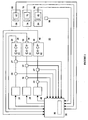
- Figure 1 is a block diagram of a light-emitting element luminaire according to one embodiment of the present invention.
- light-emitting element is used to define any device that emits radiation in any region or combination of regions of the electromagnetic spectrum for example, the visible region, infrared and/or ultraviolet region, when activated by applying a potential difference across it or passing a current through it, for example. Therefore a light-emitting element can have monochromatic, quasimonochromatic, polychromatic or broadband spectral emission characteristics. Examples of light-emitting elements include semiconductor, organic, or polymer/polymeric light-emitting diodes, blue or UV pumped phosphor coated light-emitting diodes, optically pumped nanocrystal light-emitting diodes or any other similar light-emitting devices as would be readily understood by a worker skilled in the art.
- output light is used to define electromagnetic radiation of a particular frequency or range of frequencies in any region of the electromagnetic spectrum for example, the visible, infrared and ultraviolet regions, or any combination of regions of the electromagnetic spectrum, generated by a one or more of light-emitting elements.
- luminous flux is used to define the amount of light emitted by a light source according to standards of the Commission Internationale de l'Eclairage (CIE). Where the wavelength regime of interest includes infrared and/or ultraviolet wavelengths, the term “luminous flux” is used to include radiant flux as defined by CIE standards.
- CIE Commission Internationale de l'Eclairage
- spectral radiant flux is used to define the quantity of radiant flux per unit wavelength at each wavelength emitted by a light source according to CIE standards.
- chromaticity is used to define the perceived colour impression of light according to CIE standards.
- substrate is used to define a thermally conductive material with which a light-emitting element is in thermal contact and capable of transferring heat generated by the light-emitting element thereto.
- the present invention can alleviate these problems by considering one or more of the following: heat sink temperature, substrate temperature, instantaneous forward current and time-averaged forward current. Based on these parameters, as well as empirical characteristics of the sensors and the light-emitting elements, a feedback controller can make adjustments to drive currents in order to substantially maintain the output light of the luminaire at the desired chromaticity or CCT.
- the present invention provides a luminaire system capable of generating light of a desired chromaticity and luminous flux output during continuous operation with varying ambient operating temperature.
- the luminaire system can be further capable of maintaining a desired correlated colour temperature during dimming of the luminaire.
- the luminaire system comprises one or more arrays of light-emitting elements for generating light.
- a current driver system is coupled to the arrays and can selectively supply electrical drive current to each of the arrays, wherein the current driver system is responsive to drive signals received from a controller.
- the luminaire system further comprises an optical sensor system which captures a predetermined portion of the generated light and generates optical signals representative of chromaticity and luminous flux output of the predetermined portion of the light.
- a heat sensing system is operatively coupled to the one or more arrays and provides a means for generating signals representative of the junction temperatures of arrays of light-emitting elements during operation.
- the luminaire system further comprises a controller that is operatively connected to the current driver system, the optical sensor system and the heat sensing system for receiving the signals generated by each of these systems.
- the controller is configured to generate one or more drive signals for transmission to the current driver system in response to the optical signals and thermal signals received from the optical system and the heat sensing system, respectively.
- the controller is thereby enabled to modify the light emitted by the arrays of light-emitting elements having specific regard to current light output, desired light output and the variations in light output from the arrays of light-emitting elements based on junction temperature thereof.
- Current sensors 29, 39, 49 are coupled to the output of current drivers 28, 38, 48 and measure the instantaneous forward current supplied to the light-emitting element arrays 20, 30, 40.
- the current sensors 29, 39, 49 are optionally a fixed resistor, a variable resistor, an inductor, a Hall effect current sensor, or other element which has a known voltage-current relationship and can provide a measurement of the current flowing through the load, for example an array of one or more light-emitting elements, based on a measured voltage signal.
- the peak forward currents for each array 20, 30, or 40 can be fixed to a pre-set value to avoid measuring both the forward and instantaneous current supplied to arrays 20, 30, 40 at a given time.
- a controller 50 is coupled to current drivers 28, 38, 48.
- the controller 50 is configured to independently adjust the amount of average forward current by adjusting the duty cycle of the current drivers 28, 38, 48, thereby providing control of the luminous flux output.
- the controller 50 can also be coupled to current sensors 29, 39, 49 and can be configured to monitor the instantaneous forward current supplied to the arrays 20, 30, 40 as provided by the current drivers 28, 38, 48.
- voltage sensors 27, 37, 47 are coupled to the output of current drivers 28, 38, 48 and measure the instantaneous forward voltage of light-emitting element arrays 20, 30, 40.
- Controller 50 is coupled to voltage sensors 27, 37, 47 and configured to monitor the instantaneous forward voltage of light-emitting element arrays 20, 30, 40. Because the junction temperature of a light-emitting element nonlinearly depends on the drive current, it is possible to determine the light-emitting element junction temperature by measuring the light-emitting element forward voltage, for example.
- the luminaire 10 further includes optical sensor systems 60, 70, 80 which can be operatively coupled to a proportional-integral-derivative (PID) feedback loop configuration with PID controller 90 that can be embedded in controller 50 in firmware.
- PID controller 90 can be a separate component operatively connected to the controller 50.
- Each optical sensor system 60, 70, 80 generates a signal representative of the average spectral radiant flux from arrays 20, 30, 40.
- Each optical sensor system 60, 70, 80 includes, for example, optical sensors 62, 72, 82, which can be for example a photodiode, responsive to spectral radiant flux emitted by the arrays 20, 30, 40.
- each optical sensor 62, 72, 82 can be configured to be sensitive to light of a narrow wavelength regime.
- red, green and blue optical sensors 62, 72, 82 can be used to measure the contribution from red light-emitting elements 22, green light-emitting elements 32 and blue light-emitting elements 42, respectively.
- each optical sensor 62, 72, 82 may be equipped with a filter 64, 74, 84 that can approximate, for example, the CIE V-lambda response of the human eye to the spectral power distribution of the output light.
- Variations in the ambient operating temperature can affect the output signal of optical sensor systems 60, 70, 80.
- the luminaire comprises a temperature sensor 86 for sensing the operating temperature of the optical sensor systems 60, 70 and 80.
- the temperature dependence of the sensitivity of each optical sensor 62, 72, 82 is approximated in a first-order polynomial equation using coefficients suitable for a linear approximation which can be used to correct for the effects of temperature dependence of the optical sensor readings and to obtain a more accurate indication of the output light of the arrays 20, 30, 40.
- a polynomial-based correction can be implemented in controller 50 which can be configured with the polynomial coefficients to process the optical signals and compensate the respective drive currents for varying temperature operating conditions of the optical sensors 62, 72, 82.
- Evaluation of the polynomial equation can be performed by for example floating-point or fixed-point calculations or indexing of a lookup table.
- higher-order polynomial equations can be used to model the parametric temperature dependency of the optical sensors as would be readily understood by those skilled in the art. Evaluation of the polynomial equations can be performed by the controller 50.
- the equation coefficients can be determined by computer simulation of a model luminaire or by experimental acquisition of empirical data of a luminaire and subsequently stored in memory of the controller 50. Alternatively, the equation can be pre-calculated and the results stored in a look-up table in the memory of the controller 50.
- the coefficients can be different for each optical sensor system 60, 70, 80.
- the temperature dependencies of the optical sensors 62, 72, 82 may not be the same for all wavelengths.
- temperature dependencies can be governed by the material properties of the optical sensor 62, 72, 82 and any optional filters 64, 74, 84.
- a photodiode with a red filter will have different temperature dependency than a photodiode with a green filter.
- the sensitivity of silicon photodiodes to temperature variations in the red region of the visible spectrum is usually more pronounced than it is in the green region. Therefore, equation coefficients expressing temperature dependency for the red-filtered photodiode can be different from those for a green-filtered photodiode.
- the coefficients can be related to the inherent characteristics of the optical sensor 62, 72, 82 and may vary between different types of sensors.
- temperature sensors 26, 36, 46 can be implemented using a thermistor, thermocouple, light-emitting element forward voltage measurement, integrated temperature sensing circuits, or any other device or method that is responsive to variations in temperature as contemplated by those skilled in the art.
- the amount of forward current supplied to the arrays 20, 30, 40 can cause variations in junction temperature beyond what may be measured at the one or more heat sinks and in turn can cause shifting in the peak wavelength of light generated by the red light-emitting elements 22, green light-emitting elements 32 and blue light-emitting elements 42.
- the effect of the forward current can become an important consideration in luminaires using PWM or PCM to control the luminous flux output. For example, in order to reduce the effect of the forward current-induced wavelength variations, the instantaneous forward current of the red light-emitting elements 22, green light-emitting elements 32 and blue light-emitting elements 42 can be kept at a constant level during the ON cycle.
- This junction temperature change of the red light-emitting elements 22, green light-emitting elements 32 and blue light-emitting elements 42 can cause a spectral shift in the peak wavelength of light generated by each of the red light-emitting elements 22, green light-emitting elements 32 and blue light-emitting elements 42 which may not be accounted for by temperature sensors 26, 36, 46 when measuring the temperature of the one or more heat sinks.
- another polynomial-based correction relating to peak wavelength shift due to variations in the average forward current can be derived during calibration of the luminaire 10. This polynomial-based correction can be used by the controller 50 to compensate for wavelength deviations when varying the duty cycle and subsequently the average forward current to current drivers 28, 38, 48.
- the junction temperature for each array 20, 30, 40 can be determined from the forward voltage as measured by voltage sensor 27, 37, 47.
- a corresponding polynomial-based correction can implemented by controller 50 to compensate for peak wavelength shift due to junction temperature.
- Step S1 shows a sequence of steps for the control process performed by the controller 50 in accordance with one embodiment of the present invention.
- the user preference for colour temperature or more generally chromaticity and luminous flux output or dimming level are input to controller 50 in Step S2 and Step S3, respectively.
- Information relating to characteristics of the red light-emitting elements 22, green light-emitting elements 32 and blue light-emitting elements 42, characteristics of temperature sensors 26, 36, 46 and optical sensors 62, 72, 82 are stored in the controller 50 at Step S4 either at startup or during calibration.
- Step S5 the controller 50 obtains the colour temperature and dimming level input by the user in Steps S2 and S3.
- Step S8 the target optical sensor response levels are communicated to the PID controller 90 in the PID loop configuration with controller 50.
- the error inputs to the PID loop are based on target and measured optical sensor responses.
- the controller 50 adjusts the duty cycle of the PWM control signal for current drivers 28, 38, 48 based on values from PID controller 50.
- Step 9 The controller 50 waits for a predetermined time in order to allow the feedback loop to make the appropriate adjustments, then returns to Step S5.
Landscapes
- Circuit Arrangement For Electric Light Sources In General (AREA)
Abstract
Claims (9)
- Système de luminaire (10) pour générer de la lumière qui présente une chromaticité souhaitée et un rendement souhaité du flux lumineux, le système de luminaire comprenant :(a) un ou plusieurs réseaux (20, 30, 40), chaque réseau comprenant un ou plusieurs éléments émetteurs de lumière (22, 32, 42) pour générer de la lumière ; l'un ou plusieurs réseaux étant en contact thermique avec un ou avec plusieurs dissipateurs de chaleur ;(b) un système de commande de courant (28, 38, 48) qui est couplé de façon opérationnelle à l'un ou à plusieurs réseaux (20, 30, 40), le système de commande de courant étant destiné à fournir sélectivement du courant de commande électrique à chacun de l'un ou de plusieurs réseaux, le système de commande électrique étant sensible à l'un ou à plusieurs signaux d' attaque ;(c) un ou plusieurs systèmes de capteurs optiques (60, 70, 80) qui sont couplés de façon opérationnelle à l'un ou à plusieurs éléments émetteurs de lumière (22, 32, 42), chaque système de capteurs optiques comprenant un ou plusieurs capteurs optiques (62, 72, 82) pour capter une partie prédéterminée de la lumière qui est générée par les éléments émetteurs de lumière, chaque système de capteurs optiques (60, 70, 80) étant configuré de manière à générer des signaux optiques qui sont représentatifs de la chromaticité et du rendement du flux lumineux de la partie prédéterminée de la lumière ;(d) un système de détection de chaleur qui est couplé de façon opérationnelle à l'un ou à plusieurs réseaux, le système de détection de chaleur comprenant un ou plusieurs capteurs de température (26, 36, 46) qui sont en contact thermique avec l'un ou avec plusieurs dissipateurs de chaleur pour mesurer des signaux de température qui sont représentatifs d'une première valeur de la température de jonction de chacun de l'un ou de plusieurs éléments émetteurs de lumière (22, 32, 42) ; et(e) un contrôleur (50) qui est connecté de façon opérationnelle au système de commande de courant (28, 38, 48), à l'un ou à plusieurs systèmes de capteurs optiques (60, 70, 80) et au système de détection de chaleur ; le contrôleur (50) étant configuré de manière à générer l'un ou plusieurs signaux d'attaque sur la base desdits signaux optiques et de la chromaticité souhaitée et du rendement souhaité du flux lumineux, et dans lequel le système de luminaire (10) est adapté de manière à être connecté à une source d'énergie,caractérisé en ce que :le système de détection de chaleur comprend en outre un système de détection de tension comprenant un ou plusieurs capteurs de tension (27, 37, 47) pour mesurer des signaux de tension directe qui sont représentatifs de la tension directe à l'un ou à plusieurs des réseaux (20, 30, 40) ;le contrôleur (50) est en outre configuré de manière à évaluer une deuxième valeur de la température de jonction de l'un ou de plusieurs éléments émetteurs de lumière (22, 32, 42) sur la base des signaux de tension directe ;le contrôleur est configuré de manière à évaluer un premier facteur de modification qui est défini par une relation entre la première valeur de la température de jonction et les caractéristiques d'émission de lumière de l'un ou de plusieurs éléments émetteurs de lumière, dans lequel le premier facteur de modification constitue une ou plusieurs équations polynomiales ;le contrôleur est configuré de manière à évaluer un troisième facteur de modification qui est défini par une relation entre la deuxième valeur de la température de jonction et les caractéristiques d'émission de lumière de l'un ou de plusieurs éléments émetteurs de lumière, dans lequel le troisième facteur de modification constitue une ou plusieurs équations polynomiales ;le contrôleur est configuré de manière à modifier l'un ou plusieurs signaux d'attaque sur la base du premier facteur de modification en compensant de ce fait des variations de température des réseaux et du troisième facteur de modification en compensant de ce fait un décalage de longueur d'onde de pointe qui est dû à des variations dans le courant direct des réseaux.
- Système de luminaire selon la revendication 1, dans lequel le système de détection de chaleur est en outre couplé de façon opérationnelle à l'un ou à plusieurs systèmes de capteurs optiques (60, 70, 80), le système de détection de chaleur mesurant en outre des signaux de température qui sont représentatifs de la température de fonctionnement de l'un ou de plusieurs systèmes de capteurs optiques, le contrôleur (50) étant en outre configuré de manière à évaluer un deuxième facteur de modification qui est défini par une relation entre la température de fonctionnement et les signaux optiques en provenance de l'un ou de plusieurs systèmes de capteurs optiques, dans lequel le deuxième facteur de modification constitue une ou plusieurs équations polynomiales ; et le contrôleur (50) étant en outre configuré de manière à modifier l'un ou plusieurs signaux d'attaque sur la base du deuxième facteur de modification.
- Système de luminaire selon la revendication 1, comprenant en outre un système de détection de courant (29, 39, 49) qui est couplé de façon opérationnelle au système de commande de courant, le système de détection de courant étant destiné à mesurer les signaux de courant qui sont représentatifs du courant de commande électrique qui est fourni à chacun de l'un ou de plusieurs réseaux (20, 30, 40) et le contrôleur (50) étant en outre configuré de manière à modifier un ou plusieurs signaux d'attaque en réponse aux signaux de courant.
- Système de luminaire selon la revendication 1, dans lequel un ou plusieurs des systèmes de capteurs optiques (60, 70, 80) comprennent un filtre optique (64, 74, 84) qui est couplé de façon optique à un des capteurs optiques (62, 72, 82).
- Système de luminaire selon la revendication 4, dans lequel le filtre optique (64, 74, 84) présente des caractéristiques de filtrage prédéterminées.
- Système de luminaire selon la revendication 4, dans lequel le filtre optique (64, 74, 84) présente des caractéristiques de filtrage contrôlables.
- Procédé pour commander le fonctionnement de l'un ou de plusieurs réseaux dans un système de luminaire (10) afin de générer de la lumière qui présente une chromaticité souhaitée et un rendement souhaité du flux lumineux, chaque réseau comprenant un ou plusieurs éléments émetteurs de lumière (22, 32, 42) qui sont en contact thermique avec un ou avec plusieurs dissipateurs de chaleur, le procédé comprenant les étapes suivantes consistant à :(a) fournir des courants de commande aux éléments émetteurs de lumière (22, 32, 42) pour générer de la lumière ;(b) mesurer des signaux optiques par un système de détection optique (60, 70, 80) qui est représentatif de la lumière étant générée ;(c) mesurer des signaux de température en provenance de l'un ou de plusieurs dissipateurs de chaleur qui sont représentatifs des premières valeurs de la température de jonction des éléments émetteurs de lumière (22, 32, 42) ;caractérisé en ce que le procédé comprend en outre les étapes suivantes consistant à :(d) mesurer des signaux de tension directe qui sont représentatifs des courants de commande aux éléments émetteurs de lumière (22, 32, 42) ;(e) évaluer des deuxièmes valeurs de la température de jonction des éléments émetteurs de lumière (22, 32, 42) sur la base des signaux de tension directe ;(f) évaluer un premier facteur de modification qui est défini par une relation entre lesdites premières valeurs de la température de jonction et les caractéristiques d'émission de lumière des éléments émetteurs de lumière (22, 32, 42), dans lequel le premier facteur de modification constitue une ou plusieurs équations polynomiales ;(g) évaluer un troisième facteur de modification qui est défini par une relation entre lesdites deuxièmes valeurs de la température de jonction et les caractéristiques d'émission de lumière des éléments émetteurs de lumière (22, 32, 42), dans lequel le troisième facteur de modification constitue une ou plusieurs équations polynomiales ;(h) déterminer de nouveaux courants de commande sur la base des signaux optiques mesurés, le premier facteur de modification compensant de ce fait des variations de température des réseaux et le troisième facteur de modification compensant de ce fait un décalage de longueur d'onde de pointe qui est dû à des variations dans le courant direct des réseaux ; et(i) fournir les nouveaux courants de commande aux éléments émetteurs de lumière (22, 32, 42) en commandant de ce fait le fonctionnement des éléments émetteurs de lumière pour générer de la lumière qui présente une chromaticité souhaitée et un rendement souhaité du flux lumineux.
- Procédé selon la revendication 7, dans lequel, après l'étape (c), on exécute les étapes suivantes consistant à :(a) mesurer des signaux de température qui sont représentatifs de la température de fonctionnement du système de détection optique (60, 70, 80) ; et(b) évaluer un deuxième facteur de modification qui est défini par une relation entre la température de fonctionnement et les signaux optiques en provenance du système de capteurs optiques, dans lequel le deuxième facteur de modification constitue une ou plusieurs équations polynomiales ;dans lequel l'étape suivante consistant à déterminer de nouveaux courants de commande est en outre basée sur le deuxième facteur de modification.
- Procédé selon la revendication 7, dans lequel, après l'étape (a) on exécute l'étape suivante consistant à mesurer des signaux de courant qui sont représentatifs du courant de commande électrique qui est fourni aux éléments émetteurs de lumière (22, 32, 42), dans lequel l'étape suivante consistant à déterminer de nouveaux courants de commande est en outre basée sur les signaux de courant mesurés.
Applications Claiming Priority (2)
| Application Number | Priority Date | Filing Date | Title |
|---|---|---|---|
| US70921705P | 2005-08-17 | 2005-08-17 | |
| PCT/CA2005/001902 WO2007019663A1 (fr) | 2005-08-17 | 2005-12-16 | Systeme de luminaire a commande numerique |
Publications (3)
| Publication Number | Publication Date |
|---|---|
| EP1922905A1 EP1922905A1 (fr) | 2008-05-21 |
| EP1922905A4 EP1922905A4 (fr) | 2011-02-23 |
| EP1922905B1 true EP1922905B1 (fr) | 2012-07-04 |
Family
ID=37757272
Family Applications (1)
| Application Number | Title | Priority Date | Filing Date |
|---|---|---|---|
| EP05820993A Expired - Lifetime EP1922905B1 (fr) | 2005-08-17 | 2005-12-16 | Systeme de luminaire a commande numerique |
Country Status (5)
| Country | Link |
|---|---|
| US (1) | US7319298B2 (fr) |
| EP (1) | EP1922905B1 (fr) |
| CN (1) | CN101292574B (fr) |
| CA (1) | CA2619613C (fr) |
| WO (1) | WO2007019663A1 (fr) |
Families Citing this family (270)
| Publication number | Priority date | Publication date | Assignee | Title |
|---|---|---|---|---|
| EP1579734A1 (fr) * | 2002-12-20 | 2005-09-28 | Koninklijke Philips Electronics N.V. | Detection de lumiere emise a partir de plusieurs sources lumineuses |
| US20050259424A1 (en) * | 2004-05-18 | 2005-11-24 | Zampini Thomas L Ii | Collimating and controlling light produced by light emitting diodes |
| US7619193B2 (en) * | 2005-06-03 | 2009-11-17 | Koninklijke Philips Electronics N.V. | System and method for controlling a LED luminary |
| US8278846B2 (en) * | 2005-11-18 | 2012-10-02 | Cree, Inc. | Systems and methods for calibrating solid state lighting panels |
| US7926300B2 (en) | 2005-11-18 | 2011-04-19 | Cree, Inc. | Adaptive adjustment of light output of solid state lighting panels |
| US8514210B2 (en) * | 2005-11-18 | 2013-08-20 | Cree, Inc. | Systems and methods for calibrating solid state lighting panels using combined light output measurements |
| KR20070058087A (ko) * | 2005-12-01 | 2007-06-07 | 삼성전자주식회사 | 백라이트 유닛, 그 구동방법 및 이를 포함하는액정표시장치 |
| US8022632B2 (en) * | 2006-01-19 | 2011-09-20 | Koninklijke Philips Electronics N.V. | Color-controlled illumination device |
| KR100691628B1 (ko) * | 2006-04-07 | 2007-03-12 | 삼성전기주식회사 | Led 어레이 구동 장치 |
| US8159150B2 (en) * | 2006-04-21 | 2012-04-17 | Koninklijke Philips Electronics N.V. | Method and apparatus for light intensity control |
| US7766511B2 (en) * | 2006-04-24 | 2010-08-03 | Integrated Illumination Systems | LED light fixture |
| EP2035745B1 (fr) * | 2006-05-31 | 2020-04-29 | IDEAL Industries Lighting LLC | Dispositif d'eclairage avec controle des couleurs et procede d'eclairage |
| DE602007003360D1 (de) * | 2006-06-20 | 2009-12-31 | Koninkl Philips Electronics Nv | Beleuchtungssystem mit mehreren lichtquellen |
| US7742273B1 (en) * | 2006-07-31 | 2010-06-22 | Shvartsman Vladimir A | Self-protected, intelligent, power control module |
| KR20080024323A (ko) * | 2006-09-13 | 2008-03-18 | 삼성전자주식회사 | 액정표시장치 및 액정표시장치의 구동방법 |
| KR100758987B1 (ko) * | 2006-09-26 | 2007-09-17 | 삼성전자주식회사 | Led 발광 장치 및 그 제어 방법 |
| KR100968451B1 (ko) * | 2006-10-16 | 2010-07-07 | 삼성전자주식회사 | 디스플레이장치 및 그 제어방법 |
| KR101283246B1 (ko) * | 2006-10-25 | 2013-07-11 | 엘지이노텍 주식회사 | 멀티센서가 구비된 백라이트 유닛 |
| US8129924B2 (en) | 2006-11-13 | 2012-03-06 | Cypress Semiconductor Corporation | Stochastic signal density modulation for optical transducer control |
| US8093825B1 (en) | 2006-11-13 | 2012-01-10 | Cypress Semiconductor Corporation | Control circuit for optical transducers |
| US7729941B2 (en) | 2006-11-17 | 2010-06-01 | Integrated Illumination Systems, Inc. | Apparatus and method of using lighting systems to enhance brand recognition |
| US8362838B2 (en) * | 2007-01-19 | 2013-01-29 | Cirrus Logic, Inc. | Multi-stage amplifier with multiple sets of fixed and variable voltage rails |
| US8013538B2 (en) | 2007-01-26 | 2011-09-06 | Integrated Illumination Systems, Inc. | TRI-light |
| US8044612B2 (en) * | 2007-01-30 | 2011-10-25 | Cypress Semiconductor Corporation | Method and apparatus for networked illumination devices |
| US7667408B2 (en) * | 2007-03-12 | 2010-02-23 | Cirrus Logic, Inc. | Lighting system with lighting dimmer output mapping |
| US20080224631A1 (en) * | 2007-03-12 | 2008-09-18 | Melanson John L | Color variations in a dimmable lighting device with stable color temperature light sources |
| US7804256B2 (en) * | 2007-03-12 | 2010-09-28 | Cirrus Logic, Inc. | Power control system for current regulated light sources |
| US8076920B1 (en) | 2007-03-12 | 2011-12-13 | Cirrus Logic, Inc. | Switching power converter and control system |
| US7288902B1 (en) * | 2007-03-12 | 2007-10-30 | Cirrus Logic, Inc. | Color variations in a dimmable lighting device with stable color temperature light sources |
| US8018171B1 (en) | 2007-03-12 | 2011-09-13 | Cirrus Logic, Inc. | Multi-function duty cycle modifier |
| JP4970095B2 (ja) * | 2007-03-19 | 2012-07-04 | 富士フイルム株式会社 | 照明装置及びその発光方法、並びに撮影装置 |
| US7592757B2 (en) * | 2007-03-29 | 2009-09-22 | Magna International Inc. | System and method for dimming one or more light source |
| WO2008120133A2 (fr) * | 2007-03-29 | 2008-10-09 | Koninklijke Philips Electronics N.V. | Procédé et dispositif pour piloter un système de del |
| US7554473B2 (en) * | 2007-05-02 | 2009-06-30 | Cirrus Logic, Inc. | Control system using a nonlinear delta-sigma modulator with nonlinear process modeling |
| US7696913B2 (en) | 2007-05-02 | 2010-04-13 | Cirrus Logic, Inc. | Signal processing system using delta-sigma modulation having an internal stabilizer path with direct output-to-integrator connection |
| EP2001132A1 (fr) * | 2007-05-30 | 2008-12-10 | Osram Gesellschaft mit Beschränkter Haftung | Appareil et méthode de commande de diodes électroluminescentes |
| US8102127B2 (en) * | 2007-06-24 | 2012-01-24 | Cirrus Logic, Inc. | Hybrid gas discharge lamp-LED lighting system |
| TW200906221A (en) * | 2007-07-19 | 2009-02-01 | Aussmak Optoelectronic Corp | Light emitting device and its calibrating and controlling method |
| CN101766056B (zh) * | 2007-08-02 | 2013-05-22 | Nxp股份有限公司 | 具有多个发光器件的电子设备 |
| US8552659B2 (en) * | 2007-08-07 | 2013-10-08 | Koninklijke Philips N.V. | Method and apparatus for discriminating modulated light in a mixed light system |
| DE102007039388A1 (de) | 2007-08-21 | 2009-02-26 | Zumtobel Lighting Gmbh | Beleuchtungsanordnung mit Lichtquelle und Sensor zum Erfassen des von der Lichtquelle angegebenen Lichts |
| DE102007044556A1 (de) * | 2007-09-07 | 2009-03-12 | Arnold & Richter Cine Technik Gmbh & Co. Betriebs Kg | Verfahren und Vorrichtung zur Einstellung der farb- oder fotometrischen Eigenschaften einer LED-Beleuchtungseinrichtung |
| US8742686B2 (en) * | 2007-09-24 | 2014-06-03 | Integrated Illumination Systems, Inc. | Systems and methods for providing an OEM level networked lighting system |
| KR101494320B1 (ko) * | 2007-10-05 | 2015-02-23 | 삼성디스플레이 주식회사 | 백라이트 어셈블리 및 이를 갖는 표시장치 |
| US7718942B2 (en) * | 2007-10-09 | 2010-05-18 | Avago Technologies Ecbu Ip (Singapore) Pte. Ltd. | Illumination and color management system |
| US8866410B2 (en) | 2007-11-28 | 2014-10-21 | Cree, Inc. | Solid state lighting devices and methods of manufacturing the same |
| DE102007059130A1 (de) * | 2007-12-07 | 2009-06-10 | Osram Gesellschaft mit beschränkter Haftung | Verfahren und Anordnung zur Einstellung eines Farborts sowie Leuchtsystem |
| US7804697B2 (en) * | 2007-12-11 | 2010-09-28 | Cirrus Logic, Inc. | History-independent noise-immune modulated transformer-coupled gate control signaling method and apparatus |
| US8189008B2 (en) * | 2007-12-13 | 2012-05-29 | Daniel John Julio | Color control intuitive touchpad |
| EP2073607A1 (fr) * | 2007-12-19 | 2009-06-24 | Data Display GmbH | Contrôleur de DEL pour optimiser la durée de vie de la DEL |
| CN101990786A (zh) * | 2008-01-17 | 2011-03-23 | 皇家飞利浦电子股份有限公司 | 用于光强度控制的方法和装置 |
| JP5749932B2 (ja) * | 2008-01-23 | 2015-07-15 | コーニンクレッカ フィリップス エヌ ヴェ | Led型照明設備における一貫性のある色校正 |
| EP2245904A2 (fr) * | 2008-01-28 | 2010-11-03 | Nxp B.V. | Système et procédé pour estimer la température de jonction d'une diode électroluminescente |
| US8008898B2 (en) * | 2008-01-30 | 2011-08-30 | Cirrus Logic, Inc. | Switching regulator with boosted auxiliary winding supply |
| US7755525B2 (en) * | 2008-01-30 | 2010-07-13 | Cirrus Logic, Inc. | Delta sigma modulator with unavailable output values |
| US8022683B2 (en) | 2008-01-30 | 2011-09-20 | Cirrus Logic, Inc. | Powering a power supply integrated circuit with sense current |
| US8576589B2 (en) | 2008-01-30 | 2013-11-05 | Cirrus Logic, Inc. | Switch state controller with a sense current generated operating voltage |
| US8368319B2 (en) * | 2008-02-07 | 2013-02-05 | Nxp B.V. | Multi-core light engine architecture |
| JP4525767B2 (ja) * | 2008-02-14 | 2010-08-18 | ソニー株式会社 | 照明装置及び表示装置 |
| WO2009107082A1 (fr) * | 2008-02-28 | 2009-09-03 | Koninklijke Philips Electronics N.V. | Dispositif et procédé de mesure de chromaticité de la lumière |
| US8493300B2 (en) * | 2008-03-11 | 2013-07-23 | Atmel Corporation | Architecture and technique for inter-chip communication |
| US8378957B2 (en) * | 2008-04-28 | 2013-02-19 | Atmel Corporation | Methods and circuits for triode region detection |
| US8581810B2 (en) * | 2008-03-11 | 2013-11-12 | Atmel Corporation | Methods and circuits for self-calibrating controller |
| WO2009113055A2 (fr) * | 2008-03-13 | 2009-09-17 | Microsemi Corp. - Analog Mixed Signal Group, Ltd. | Dispositif de commande de couleur pour luminaire |
| CN102037278B (zh) | 2008-03-20 | 2015-04-08 | 美国航易明国际有限公司 | 照明设备与装置 |
| US8915609B1 (en) | 2008-03-20 | 2014-12-23 | Cooper Technologies Company | Systems, methods, and devices for providing a track light and portable light |
| US7759881B1 (en) | 2008-03-31 | 2010-07-20 | Cirrus Logic, Inc. | LED lighting system with a multiple mode current control dimming strategy |
| WO2009138894A1 (fr) * | 2008-05-12 | 2009-11-19 | Koninklijke Philips Electronics, N.V. | Source de lumière à agrégats électroluminescents |
| US8255487B2 (en) * | 2008-05-16 | 2012-08-28 | Integrated Illumination Systems, Inc. | Systems and methods for communicating in a lighting network |
| US9001161B2 (en) | 2008-06-06 | 2015-04-07 | Dolby Laboratories Licensing Corporation | Chromaticity control for solid-state illumination sources |
| JP5204563B2 (ja) * | 2008-06-24 | 2013-06-05 | パナソニック株式会社 | Led照明装置 |
| US8314572B2 (en) * | 2008-06-24 | 2012-11-20 | Atmel Corporation | Apparatus and methodology for enhancing efficiency of a power distribution system having power factor correction capability by using a self-calibrating controller |
| US8008902B2 (en) * | 2008-06-25 | 2011-08-30 | Cirrus Logic, Inc. | Hysteretic buck converter having dynamic thresholds |
| US8847719B2 (en) * | 2008-07-25 | 2014-09-30 | Cirrus Logic, Inc. | Transformer with split primary winding |
| US8344707B2 (en) | 2008-07-25 | 2013-01-01 | Cirrus Logic, Inc. | Current sensing in a switching power converter |
| US8212491B2 (en) | 2008-07-25 | 2012-07-03 | Cirrus Logic, Inc. | Switching power converter control with triac-based leading edge dimmer compatibility |
| US8487546B2 (en) | 2008-08-29 | 2013-07-16 | Cirrus Logic, Inc. | LED lighting system with accurate current control |
| US8456092B2 (en) * | 2008-09-05 | 2013-06-04 | Ketra, Inc. | Broad spectrum light source calibration systems and related methods |
| US8773336B2 (en) * | 2008-09-05 | 2014-07-08 | Ketra, Inc. | Illumination devices and related systems and methods |
| US9276766B2 (en) | 2008-09-05 | 2016-03-01 | Ketra, Inc. | Display calibration systems and related methods |
| USRE50468E1 (en) | 2008-09-05 | 2025-06-24 | Lutron Technology Company Llc | Intelligent illumination device |
| US10210750B2 (en) | 2011-09-13 | 2019-02-19 | Lutron Electronics Co., Inc. | System and method of extending the communication range in a visible light communication system |
| US8886047B2 (en) | 2008-09-05 | 2014-11-11 | Ketra, Inc. | Optical communication device, method and system |
| US8471496B2 (en) * | 2008-09-05 | 2013-06-25 | Ketra, Inc. | LED calibration systems and related methods |
| US20110063214A1 (en) * | 2008-09-05 | 2011-03-17 | Knapp David J | Display and optical pointer systems and related methods |
| US9509525B2 (en) * | 2008-09-05 | 2016-11-29 | Ketra, Inc. | Intelligent illumination device |
| US8521035B2 (en) | 2008-09-05 | 2013-08-27 | Ketra, Inc. | Systems and methods for visible light communication |
| US8674913B2 (en) | 2008-09-05 | 2014-03-18 | Ketra, Inc. | LED transceiver front end circuitry and related methods |
| US8222872B1 (en) | 2008-09-30 | 2012-07-17 | Cirrus Logic, Inc. | Switching power converter with selectable mode auxiliary power supply |
| US8179110B2 (en) * | 2008-09-30 | 2012-05-15 | Cirrus Logic Inc. | Adjustable constant current source with continuous conduction mode (“CCM”) and discontinuous conduction mode (“DCM”) operation |
| US8901823B2 (en) | 2008-10-24 | 2014-12-02 | Ilumisys, Inc. | Light and light sensor |
| DE102008057347A1 (de) * | 2008-11-14 | 2010-05-20 | Osram Opto Semiconductors Gmbh | Optoelektronische Vorrichtung |
| JP5457461B2 (ja) | 2008-12-05 | 2014-04-02 | コーニンクレッカ フィリップス エヌ ヴェ | 複数の照明セグメントの照明特性を制御する方法及びシステム |
| US8288954B2 (en) | 2008-12-07 | 2012-10-16 | Cirrus Logic, Inc. | Primary-side based control of secondary-side current for a transformer |
| US7990077B2 (en) * | 2008-12-12 | 2011-08-02 | Cheng Uei Precision Industry Co., Ltd. | LED control circuit |
| US8362707B2 (en) | 2008-12-12 | 2013-01-29 | Cirrus Logic, Inc. | Light emitting diode based lighting system with time division ambient light feedback response |
| US8299722B2 (en) | 2008-12-12 | 2012-10-30 | Cirrus Logic, Inc. | Time division light output sensing and brightness adjustment for different spectra of light emitting diodes |
| DE102008064149A1 (de) * | 2008-12-19 | 2010-07-01 | Osram Opto Semiconductors Gmbh | Optoelektronische Vorrichtung |
| US7994863B2 (en) | 2008-12-31 | 2011-08-09 | Cirrus Logic, Inc. | Electronic system having common mode voltage range enhancement |
| US9326346B2 (en) | 2009-01-13 | 2016-04-26 | Terralux, Inc. | Method and device for remote sensing and control of LED lights |
| US8358085B2 (en) | 2009-01-13 | 2013-01-22 | Terralux, Inc. | Method and device for remote sensing and control of LED lights |
| TW201038115A (en) * | 2009-02-20 | 2010-10-16 | Koninkl Philips Electronics Nv | Dimmable light source with temperature shift |
| EP2242333A1 (fr) * | 2009-02-27 | 2010-10-20 | Osram Gesellschaft mit Beschränkter Haftung | Procédé de compensation de vieillissement des DELs et dispositif associé |
| EP2230884B1 (fr) | 2009-03-20 | 2012-02-08 | Nxp B.V. | Procédé de contrôle d'une DEL, et contrôleur de DEL |
| US8441199B2 (en) * | 2009-03-23 | 2013-05-14 | Atmel Corporation | Method and apparatus for an intelligent light emitting diode driver having power factor correction capability |
| US20100245279A1 (en) * | 2009-03-31 | 2010-09-30 | Robe Lighting S.R.O. | Display and display control system for an automated luminaire |
| US8585245B2 (en) | 2009-04-23 | 2013-11-19 | Integrated Illumination Systems, Inc. | Systems and methods for sealing a lighting fixture |
| US8734163B1 (en) | 2009-04-28 | 2014-05-27 | Musco Corporation | Apparatus, method, and system for on-site evaluation of illumination scheme using a mobile lighting evaluation system |
| US8482223B2 (en) | 2009-04-30 | 2013-07-09 | Cirrus Logic, Inc. | Calibration of lamps |
| DE102009019288A1 (de) * | 2009-04-30 | 2010-11-11 | Adb Bvba | Leuchtschild zur Anzeige eines Gebots und/oder Hinweises für den rollenden Flugzeugverkehr auf einem Flughafen |
| WO2010143362A1 (fr) | 2009-06-11 | 2010-12-16 | パナソニック株式会社 | Dispositif d'éclairage et système d'éclairage |
| US8963535B1 (en) | 2009-06-30 | 2015-02-24 | Cirrus Logic, Inc. | Switch controlled current sensing using a hall effect sensor |
| US8212493B2 (en) | 2009-06-30 | 2012-07-03 | Cirrus Logic, Inc. | Low energy transfer mode for auxiliary power supply operation in a cascaded switching power converter |
| US8198874B2 (en) * | 2009-06-30 | 2012-06-12 | Cirrus Logic, Inc. | Switching power converter with current sensing transformer auxiliary power supply |
| US8248145B2 (en) | 2009-06-30 | 2012-08-21 | Cirrus Logic, Inc. | Cascode configured switching using at least one low breakdown voltage internal, integrated circuit switch to control at least one high breakdown voltage external switch |
| JP2011014766A (ja) * | 2009-07-03 | 2011-01-20 | Koito Mfg Co Ltd | 発光モジュールおよび車両用灯具 |
| US8836532B2 (en) | 2009-07-16 | 2014-09-16 | Gentex Corporation | Notification appliance and method thereof |
| TW201116157A (en) | 2009-08-25 | 2011-05-01 | Koninkl Philips Electronics Nv | LED-based lighting fixtures and related methods for thermal management |
| EP2470829B1 (fr) * | 2009-08-28 | 2015-10-07 | Led Illumination Holdings Llc, | Système d'éclairage à module d'éclairement remplaçable |
| WO2011032220A1 (fr) * | 2009-09-16 | 2011-03-24 | Electronic Research Pty Ltd | Système d'affichage à del |
| US10264637B2 (en) | 2009-09-24 | 2019-04-16 | Cree, Inc. | Solid state lighting apparatus with compensation bypass circuits and methods of operation thereof |
| US9713211B2 (en) | 2009-09-24 | 2017-07-18 | Cree, Inc. | Solid state lighting apparatus with controllable bypass circuits and methods of operation thereof |
| US8901845B2 (en) | 2009-09-24 | 2014-12-02 | Cree, Inc. | Temperature responsive control for lighting apparatus including light emitting devices providing different chromaticities and related methods |
| US9155174B2 (en) | 2009-09-30 | 2015-10-06 | Cirrus Logic, Inc. | Phase control dimming compatible lighting systems |
| US8264155B2 (en) * | 2009-10-06 | 2012-09-11 | Cree, Inc. | Solid state lighting devices providing visible alert signals in general illumination applications and related methods of operation |
| US8350500B2 (en) * | 2009-10-06 | 2013-01-08 | Cree, Inc. | Solid state lighting devices including thermal management and related methods |
| ES2930370T3 (es) | 2009-10-08 | 2022-12-09 | Delos Living Llc | Sistema de iluminación LED |
| EP2320125A1 (fr) * | 2009-11-04 | 2011-05-11 | Koninklijke Philips Electronics N.V. | Dispositif d'éclairage |
| US8654483B2 (en) | 2009-11-09 | 2014-02-18 | Cirrus Logic, Inc. | Power system having voltage-based monitoring for over current protection |
| JP2013517613A (ja) * | 2009-11-17 | 2013-05-16 | テララックス, インコーポレイテッド | Led電源の検出および制御 |
| US8330377B2 (en) * | 2009-12-10 | 2012-12-11 | Phoseon Technology, Inc. | Monitoring voltage to track temperature in solid state light modules |
| JP5451425B2 (ja) * | 2010-01-28 | 2014-03-26 | 矢崎総業株式会社 | 車両室内意匠の発光構造 |
| CN102141595A (zh) * | 2010-01-29 | 2011-08-03 | 旭丽电子(广州)有限公司 | 交流发光二极管的操作方法 |
| US8476836B2 (en) | 2010-05-07 | 2013-07-02 | Cree, Inc. | AC driven solid state lighting apparatus with LED string including switched segments |
| US9086435B2 (en) * | 2011-05-10 | 2015-07-21 | Arkalumen Inc. | Circuits for sensing current levels within a lighting apparatus incorporating a voltage converter |
| US8743023B2 (en) | 2010-07-23 | 2014-06-03 | Biological Illumination, Llc | System for generating non-homogenous biologically-adjusted light and associated methods |
| US8760370B2 (en) * | 2011-05-15 | 2014-06-24 | Lighting Science Group Corporation | System for generating non-homogenous light and associated methods |
| USRE49454E1 (en) | 2010-09-30 | 2023-03-07 | Lutron Technology Company Llc | Lighting control system |
| US9386668B2 (en) | 2010-09-30 | 2016-07-05 | Ketra, Inc. | Lighting control system |
| US8384294B2 (en) | 2010-10-05 | 2013-02-26 | Electronic Theatre Controls, Inc. | System and method for color creation and matching |
| US8569974B2 (en) * | 2010-11-01 | 2013-10-29 | Cree, Inc. | Systems and methods for controlling solid state lighting devices and lighting apparatus incorporating such systems and/or methods |
| US9781808B2 (en) | 2010-12-02 | 2017-10-03 | Martin Professional Aps | Method of controlling an illumination device having a number of light source arrays |
| US8593074B2 (en) | 2011-01-12 | 2013-11-26 | Electronic Theater Controls, Inc. | Systems and methods for controlling an output of a light fixture |
| US8723450B2 (en) | 2011-01-12 | 2014-05-13 | Electronics Theatre Controls, Inc. | System and method for controlling the spectral content of an output of a light fixture |
| US10178723B2 (en) | 2011-06-03 | 2019-01-08 | Cree, Inc. | Systems and methods for controlling solid state lighting devices and lighting apparatus incorporating such systems and/or methods |
| US10098197B2 (en) | 2011-06-03 | 2018-10-09 | Cree, Inc. | Lighting devices with individually compensating multi-color clusters |
| CN103392094B (zh) | 2011-02-25 | 2016-12-21 | 玛斯柯有限公司 | 紧凑可调的led照明装置以及长期运行的方法和系统 |
| US8847513B2 (en) * | 2011-03-08 | 2014-09-30 | Cree, Inc. | Method and apparatus for controlling light output color and/or brightness |
| US9066381B2 (en) | 2011-03-16 | 2015-06-23 | Integrated Illumination Systems, Inc. | System and method for low level dimming |
| US8950892B2 (en) | 2011-03-17 | 2015-02-10 | Cree, Inc. | Methods for combining light emitting devices in a white light emitting apparatus that mimics incandescent dimming characteristics and solid state lighting apparatus for general illumination that mimic incandescent dimming characteristics |
| US8939604B2 (en) | 2011-03-25 | 2015-01-27 | Arkalumen Inc. | Modular LED strip lighting apparatus |
| US9173269B2 (en) | 2011-05-15 | 2015-10-27 | Lighting Science Group Corporation | Lighting system for accentuating regions of a layer and associated methods |
| US8754832B2 (en) | 2011-05-15 | 2014-06-17 | Lighting Science Group Corporation | Lighting system for accenting regions of a layer and associated methods |
| US20120293078A1 (en) * | 2011-05-20 | 2012-11-22 | Infineon Technologies Austria Ag | LED Driver Including Color Monitoring |
| TWI441558B (zh) * | 2011-05-25 | 2014-06-11 | Nat Univ Tsing Hua | 可調整色溫之照明裝置 |
| US9839083B2 (en) | 2011-06-03 | 2017-12-05 | Cree, Inc. | Solid state lighting apparatus and circuits including LED segments configured for targeted spectral power distribution and methods of operating the same |
| US8749172B2 (en) | 2011-07-08 | 2014-06-10 | Ketra, Inc. | Luminance control for illumination devices |
| US9060400B2 (en) | 2011-07-12 | 2015-06-16 | Arkalumen Inc. | Control apparatus incorporating a voltage converter for controlling lighting apparatus |
| US20150237700A1 (en) | 2011-07-26 | 2015-08-20 | Hunter Industries, Inc. | Systems and methods to control color and brightness of lighting devices |
| US9521725B2 (en) | 2011-07-26 | 2016-12-13 | Hunter Industries, Inc. | Systems and methods for providing power and data to lighting devices |
| US10874003B2 (en) | 2011-07-26 | 2020-12-22 | Hunter Industries, Inc. | Systems and methods for providing power and data to devices |
| US11917740B2 (en) | 2011-07-26 | 2024-02-27 | Hunter Industries, Inc. | Systems and methods for providing power and data to devices |
| US8710770B2 (en) | 2011-07-26 | 2014-04-29 | Hunter Industries, Inc. | Systems and methods for providing power and data to lighting devices |
| US9609720B2 (en) | 2011-07-26 | 2017-03-28 | Hunter Industries, Inc. | Systems and methods for providing power and data to lighting devices |
| US8742671B2 (en) | 2011-07-28 | 2014-06-03 | Cree, Inc. | Solid state lighting apparatus and methods using integrated driver circuitry |
| CN103891412B (zh) | 2011-09-23 | 2015-10-14 | 马田专业公司 | 基于电流-电压模型来控制照明装置的方法 |
| JP6217957B2 (ja) * | 2011-09-29 | 2017-10-25 | 東芝ライテック株式会社 | 照明装置 |
| WO2013057834A1 (fr) * | 2011-10-21 | 2013-04-25 | Necディスプレイソリューションズ株式会社 | Dispositif de rétroéclairage et procédé de commande de rétroéclairage |
| US10043960B2 (en) | 2011-11-15 | 2018-08-07 | Cree, Inc. | Light emitting diode (LED) packages and related methods |
| US8896231B2 (en) | 2011-12-16 | 2014-11-25 | Terralux, Inc. | Systems and methods of applying bleed circuits in LED lamps |
| TW201347600A (zh) * | 2012-01-26 | 2013-11-16 | 維薩達爾電子股份有限公司 | 發光二極體應用積體電路元件及電子電路 |
| WO2013114642A1 (fr) * | 2012-01-31 | 2013-08-08 | シャープ株式会社 | Procédé de classification de del, dispositif de classification de del, programme de classification de del et support d'enregistrement |
| US10251233B2 (en) | 2012-05-07 | 2019-04-02 | Micron Technology, Inc. | Solid state lighting systems and associated methods of operation and manufacture |
| US9572226B2 (en) | 2012-07-01 | 2017-02-14 | Cree, Inc. | Master/slave arrangement for lighting fixture modules |
| US9872367B2 (en) | 2012-07-01 | 2018-01-16 | Cree, Inc. | Handheld device for grouping a plurality of lighting fixtures |
| US9980350B2 (en) | 2012-07-01 | 2018-05-22 | Cree, Inc. | Removable module for a lighting fixture |
| US9723696B2 (en) | 2012-07-01 | 2017-08-01 | Cree, Inc. | Handheld device for controlling settings of a lighting fixture |
| US10721808B2 (en) | 2012-07-01 | 2020-07-21 | Ideal Industries Lighting Llc | Light fixture control |
| US8894437B2 (en) | 2012-07-19 | 2014-11-25 | Integrated Illumination Systems, Inc. | Systems and methods for connector enabling vertical removal |
| ES2781873T3 (es) | 2012-08-28 | 2020-09-08 | Delos Living Llc | Sistemas y métodos para mejorar el bienestar asociado con ambientes habitables |
| TWI478135B (zh) * | 2012-10-25 | 2015-03-21 | Univ Nat Yunlin Sci & Tech | LED anti-light failure protection system |
| US9379578B2 (en) | 2012-11-19 | 2016-06-28 | Integrated Illumination Systems, Inc. | Systems and methods for multi-state power management |
| US9913348B2 (en) | 2012-12-19 | 2018-03-06 | Cree, Inc. | Light fixtures, systems for controlling light fixtures, and methods of controlling fixtures and methods of controlling lighting control systems |
| US9420665B2 (en) | 2012-12-28 | 2016-08-16 | Integration Illumination Systems, Inc. | Systems and methods for continuous adjustment of reference signal to control chip |
| US9485814B2 (en) | 2013-01-04 | 2016-11-01 | Integrated Illumination Systems, Inc. | Systems and methods for a hysteresis based driver using a LED as a voltage reference |
| US10231300B2 (en) | 2013-01-15 | 2019-03-12 | Cree, Inc. | Systems and methods for controlling solid state lighting during dimming and lighting apparatus incorporating such systems and/or methods |
| US10264638B2 (en) | 2013-01-15 | 2019-04-16 | Cree, Inc. | Circuits and methods for controlling solid state lighting |
| US9538603B2 (en) | 2013-04-19 | 2017-01-03 | Lutron Electronics Co., Inc. | Systems and methods for controlling color temperature |
| US9992841B2 (en) | 2013-04-19 | 2018-06-05 | Lutron Electronics Co., Inc. | Systems and methods for controlling color temperature |
| US9386654B2 (en) * | 2013-05-31 | 2016-07-05 | Damien McDermott | Controlled function light emitting diode lighting device and method |
| US9265119B2 (en) | 2013-06-17 | 2016-02-16 | Terralux, Inc. | Systems and methods for providing thermal fold-back to LED lights |
| US20150002025A1 (en) * | 2013-06-28 | 2015-01-01 | General Electric Company | Lighting assembly, apparatus and associated method for maintaining light intensities |
| US9013467B2 (en) | 2013-07-19 | 2015-04-21 | Institut National D'optique | Controlled operation of a LED lighting system at a target output color |
| USRE48956E1 (en) | 2013-08-20 | 2022-03-01 | Lutron Technology Company Llc | Interference-resistant compensation for illumination devices using multiple series of measurement intervals |
| US9247605B1 (en) | 2013-08-20 | 2016-01-26 | Ketra, Inc. | Interference-resistant compensation for illumination devices |
| US9155155B1 (en) | 2013-08-20 | 2015-10-06 | Ketra, Inc. | Overlapping measurement sequences for interference-resistant compensation in light emitting diode devices |
| US9769899B2 (en) * | 2014-06-25 | 2017-09-19 | Ketra, Inc. | Illumination device and age compensation method |
| US9578724B1 (en) | 2013-08-20 | 2017-02-21 | Ketra, Inc. | Illumination device and method for avoiding flicker |
| US9332598B1 (en) | 2013-08-20 | 2016-05-03 | Ketra, Inc. | Interference-resistant compensation for illumination devices having multiple emitter modules |
| US9651632B1 (en) | 2013-08-20 | 2017-05-16 | Ketra, Inc. | Illumination device and temperature calibration method |
| USRE48955E1 (en) | 2013-08-20 | 2022-03-01 | Lutron Technology Company Llc | Interference-resistant compensation for illumination devices having multiple emitter modules |
| US9345097B1 (en) | 2013-08-20 | 2016-05-17 | Ketra, Inc. | Interference-resistant compensation for illumination devices using multiple series of measurement intervals |
| US9237620B1 (en) | 2013-08-20 | 2016-01-12 | Ketra, Inc. | Illumination device and temperature compensation method |
| US9360174B2 (en) | 2013-12-05 | 2016-06-07 | Ketra, Inc. | Linear LED illumination device with improved color mixing |
| US9736895B1 (en) | 2013-10-03 | 2017-08-15 | Ketra, Inc. | Color mixing optics for LED illumination device |
| US9146028B2 (en) | 2013-12-05 | 2015-09-29 | Ketra, Inc. | Linear LED illumination device with improved rotational hinge |
| US10154569B2 (en) | 2014-01-06 | 2018-12-11 | Cree, Inc. | Power over ethernet lighting fixture |
| CA2940766A1 (fr) | 2014-02-28 | 2015-09-03 | Delos Living Llc | Systemes, procedes et articles pour ameliorer le bien-etre associe a des environnements habitables |
| US9338851B2 (en) | 2014-04-10 | 2016-05-10 | Institut National D'optique | Operation of a LED lighting system at a target output color using a color sensor |
| TWI496507B (zh) | 2014-05-20 | 2015-08-11 | Maintech Semiconductor Inc | 發光二極體電路及其驅動方法 |
| US9549448B2 (en) | 2014-05-30 | 2017-01-17 | Cree, Inc. | Wall controller controlling CCT |
| US10278250B2 (en) * | 2014-05-30 | 2019-04-30 | Cree, Inc. | Lighting fixture providing variable CCT |
| US9557214B2 (en) | 2014-06-25 | 2017-01-31 | Ketra, Inc. | Illumination device and method for calibrating an illumination device over changes in temperature, drive current, and time |
| US9736903B2 (en) | 2014-06-25 | 2017-08-15 | Ketra, Inc. | Illumination device and method for calibrating and controlling an illumination device comprising a phosphor converted LED |
| US9392663B2 (en) | 2014-06-25 | 2016-07-12 | Ketra, Inc. | Illumination device and method for controlling an illumination device over changes in drive current and temperature |
| US10161786B2 (en) | 2014-06-25 | 2018-12-25 | Lutron Ketra, Llc | Emitter module for an LED illumination device |
| US9392660B2 (en) | 2014-08-28 | 2016-07-12 | Ketra, Inc. | LED illumination device and calibration method for accurately characterizing the emission LEDs and photodetector(s) included within the LED illumination device |
| WO2016032772A1 (fr) * | 2014-08-28 | 2016-03-03 | Ketra, Inc. | Dispositif d'éclairage à led et procédés pour caractériser et commande avec précision les led d'émission et photodétecteurs inclus dans le dispositif d'éclairage à led |
| US9510416B2 (en) | 2014-08-28 | 2016-11-29 | Ketra, Inc. | LED illumination device and method for accurately controlling the intensity and color point of the illumination device over time |
| FI128468B (en) * | 2014-11-24 | 2020-06-15 | Flexbright Oy | Flexible illuminating multilayer structure |
| EP3245631A4 (fr) | 2015-01-13 | 2018-06-27 | Delos Living, LLC | Systèmes, procédés et articles permettant de surveiller et d'améliorer le bien-être humain |
| US9237612B1 (en) | 2015-01-26 | 2016-01-12 | Ketra, Inc. | Illumination device and method for determining a target lumens that can be safely produced by an illumination device at a present temperature |
| US9237623B1 (en) | 2015-01-26 | 2016-01-12 | Ketra, Inc. | Illumination device and method for determining a maximum lumens that can be safely produced by the illumination device to achieve a target chromaticity |
| US9485813B1 (en) | 2015-01-26 | 2016-11-01 | Ketra, Inc. | Illumination device and method for avoiding an over-power or over-current condition in a power converter |
| US9992829B2 (en) | 2015-05-05 | 2018-06-05 | Arkalumen Inc. | Control apparatus and system for coupling a lighting module to a constant current DC driver |
| US10568180B2 (en) | 2015-05-05 | 2020-02-18 | Arkalumen Inc. | Method and apparatus for controlling a lighting module having a plurality of LED groups |
| US10225904B2 (en) | 2015-05-05 | 2019-03-05 | Arkalumen, Inc. | Method and apparatus for controlling a lighting module based on a constant current level from a power source |
| US9992836B2 (en) | 2015-05-05 | 2018-06-05 | Arkawmen Inc. | Method, system and apparatus for activating a lighting module using a buffer load module |
| US10228711B2 (en) | 2015-05-26 | 2019-03-12 | Hunter Industries, Inc. | Decoder systems and methods for irrigation control |
| US10918030B2 (en) | 2015-05-26 | 2021-02-16 | Hunter Industries, Inc. | Decoder systems and methods for irrigation control |
| US10030844B2 (en) | 2015-05-29 | 2018-07-24 | Integrated Illumination Systems, Inc. | Systems, methods and apparatus for illumination using asymmetrical optics |
| US10060599B2 (en) | 2015-05-29 | 2018-08-28 | Integrated Illumination Systems, Inc. | Systems, methods and apparatus for programmable light fixtures |
| US9661712B1 (en) * | 2016-04-15 | 2017-05-23 | Avertronics Inc. | Lamp with automatic dimmer |
| DE102016108754A1 (de) | 2016-05-11 | 2017-11-16 | Schott Ag | Beleuchtungsvorrichtung mit konsistenten Lichteigenschaften |
| CN105898929A (zh) * | 2016-05-27 | 2016-08-24 | 合肥工业大学 | 一种基于最佳光效的led电光源自适应控制装置及其自适应控制方法 |
| US9967944B2 (en) | 2016-06-22 | 2018-05-08 | Cree, Inc. | Dimming control for LED-based luminaires |
| DE102016213192A1 (de) * | 2016-07-19 | 2018-01-25 | BSH Hausgeräte GmbH | Reduktion von Helligkeitsunterschieden beim Betrieb einer Beleuchtungsvorrichtung eines Haushaltsgeräts mit mehreren Leuchtmitteln |
| WO2018039433A1 (fr) | 2016-08-24 | 2018-03-01 | Delos Living Llc | Systèmes, procédés et articles permettant d'accroître le bien-être associé à des environnements habitables |
| US10595380B2 (en) | 2016-09-27 | 2020-03-17 | Ideal Industries Lighting Llc | Lighting wall control with virtual assistant |
| US20180172266A1 (en) * | 2016-12-21 | 2018-06-21 | Electric Horsepower Inc. | Electric resistance heater system and light tower |
| EP3586570A1 (fr) | 2017-02-22 | 2020-01-01 | Signify Holding B.V. | Optimisation de commande de luminaire multicanaux à l'aide d'une matrice de coefficients de couleur |
| WO2018153713A1 (fr) * | 2017-02-22 | 2018-08-30 | Philips Lighting Holding B.V. | Optimisation de commande de luminaire multicanaux à l'aide d'une matrice de coefficients de couleur |
| DE102017105131A1 (de) | 2017-03-10 | 2018-09-13 | Osram Opto Semiconductors Gmbh | Verfahren zum Betreiben eines optoelektronischen Bauelements und optoelektronisches Bauelement |
| US10299321B1 (en) * | 2017-05-08 | 2019-05-21 | Eaton Intelligent Power Limited | Multi-channel white light tuning |
| WO2018207423A1 (fr) * | 2017-05-09 | 2018-11-15 | ソニー株式会社 | Système source de lumière médicale, dispositif source de lumière médicale et procédé de réglage de l'intensité lumineuse d'un dispositif source de lumière médicale |
| US10303920B2 (en) * | 2017-07-09 | 2019-05-28 | Lumenetix, Inc. | Techniques for creating characterization matrices for reflectance, illuminance, or sensor response |
| US11263428B2 (en) * | 2017-07-09 | 2022-03-01 | Ringo Ai, Inc. | Electromagnetic emitters and detectors for electronic devices |
| WO2019046580A1 (fr) | 2017-08-30 | 2019-03-07 | Delos Living Llc | Systèmes, procédés et articles pour évaluer et/ou améliorer la santé et le bien-être |
| US10595373B2 (en) * | 2017-10-31 | 2020-03-17 | Fulham Company Limited | Methods and apparatuses to provide dimming for a light emitting diode system |
| WO2019147763A2 (fr) * | 2018-01-26 | 2019-08-01 | Excelitas Canada, Inc. | Maintien de sortie optique stable d'un système d'éclairage à semi-conducteurs |
| US11272599B1 (en) | 2018-06-22 | 2022-03-08 | Lutron Technology Company Llc | Calibration procedure for a light-emitting diode light source |
| CN112203574B (zh) * | 2018-06-27 | 2024-09-24 | 奥林巴斯株式会社 | 内窥镜系统、内窥镜用光源装置和内窥镜 |
| US10212793B1 (en) * | 2018-07-16 | 2019-02-19 | Logitech Europe S.A. | Bandwidth optimization for streaming lighting effects |
| US11649977B2 (en) | 2018-09-14 | 2023-05-16 | Delos Living Llc | Systems and methods for air remediation |
| US10723263B2 (en) * | 2018-11-07 | 2020-07-28 | Continental Automotive Systems, Inc. | Specific color generation with multicolor LED for precise color backlight illumination applications |
| CN113272632B (zh) * | 2018-12-27 | 2024-07-05 | ams传感器德国有限公司 | 传感器系统中温度效应的补偿 |
| US11844163B2 (en) | 2019-02-26 | 2023-12-12 | Delos Living Llc | Method and apparatus for lighting in an office environment |
| US11898898B2 (en) | 2019-03-25 | 2024-02-13 | Delos Living Llc | Systems and methods for acoustic monitoring |
| FR3097937B1 (fr) * | 2019-06-28 | 2021-09-03 | Valeo Vision | Dispositif et procede de controle d'un ensemble de sources lumineuses pour vehicule automobile |
| JP7377025B2 (ja) * | 2019-08-27 | 2023-11-09 | 株式会社ジャパンディスプレイ | 検出装置 |
| US10801714B1 (en) | 2019-10-03 | 2020-10-13 | CarJamz, Inc. | Lighting device |
| US12543255B2 (en) | 2020-07-14 | 2026-02-03 | Lutron Technology Company Llc | Lighting control system with light show overrides |
| US11871495B2 (en) * | 2020-07-14 | 2024-01-09 | Lutron Technology Company Llc | Lighting control system with light show overrides |
| JP7545115B2 (ja) * | 2021-03-02 | 2024-09-04 | ウシオ電機株式会社 | 光源装置及びキャリブレーション装置 |
| TWI790633B (zh) * | 2021-06-02 | 2023-01-21 | 神煜電子股份有限公司 | 具溫度補償的光感測裝置 |
| EP4514462A1 (fr) * | 2022-04-26 | 2025-03-05 | Lumitex, Inc. | Procédé et dispositif destinés à la commande de sortie de lumière en fonction de la température de jonction |
| CN114898695B (zh) * | 2022-05-23 | 2025-06-06 | 闽南师范大学 | 一种led显示模组的像素单元色坐标的合成方法及系统 |
| US12416908B2 (en) | 2022-12-29 | 2025-09-16 | Integrated Illumination Systems, Inc. | Systems and methods for manufacturing light fixtures |
| US12297996B2 (en) | 2023-02-16 | 2025-05-13 | Integrated Illumination Systems, Inc. | Cove light fixture with hidden integrated air return |
| WO2024209004A1 (fr) * | 2023-04-06 | 2024-10-10 | Ams-Osram International Gmbh | Procédé de fonctionnement d'un composant optoélectronique, procédé de fabrication d'un composant optoélectronique, composant optoélectronique et dispositif d'éclairage |
Family Cites Families (18)
| Publication number | Priority date | Publication date | Assignee | Title |
|---|---|---|---|---|
| US6127784A (en) * | 1998-08-31 | 2000-10-03 | Dialight Corporation | LED driving circuitry with variable load to control output light intensity of an LED |
| US6495964B1 (en) * | 1998-12-18 | 2002-12-17 | Koninklijke Philips Electronics N.V. | LED luminaire with electrically adjusted color balance using photodetector |
| US6127783A (en) * | 1998-12-18 | 2000-10-03 | Philips Electronics North America Corp. | LED luminaire with electronically adjusted color balance |
| US6448550B1 (en) * | 2000-04-27 | 2002-09-10 | Agilent Technologies, Inc. | Method and apparatus for measuring spectral content of LED light source and control thereof |
| US6441558B1 (en) * | 2000-12-07 | 2002-08-27 | Koninklijke Philips Electronics N.V. | White LED luminary light control system |
| US6411046B1 (en) * | 2000-12-27 | 2002-06-25 | Koninklijke Philips Electronics, N. V. | Effective modeling of CIE xy coordinates for a plurality of LEDs for white LED light control |
| US6510995B2 (en) * | 2001-03-16 | 2003-01-28 | Koninklijke Philips Electronics N.V. | RGB LED based light driver using microprocessor controlled AC distributed power system |
| US6507159B2 (en) * | 2001-03-29 | 2003-01-14 | Koninklijke Philips Electronics N.V. | Controlling method and system for RGB based LED luminary |
| US6576881B2 (en) * | 2001-04-06 | 2003-06-10 | Koninklijke Philips Electronics N.V. | Method and system for controlling a light source |
| US6689999B2 (en) * | 2001-06-01 | 2004-02-10 | Schott-Fostec, Llc | Illumination apparatus utilizing light emitting diodes |
| US6630801B2 (en) * | 2001-10-22 | 2003-10-07 | Lümileds USA | Method and apparatus for sensing the color point of an RGB LED white luminary using photodiodes |
| US6753661B2 (en) * | 2002-06-17 | 2004-06-22 | Koninklijke Philips Electronics N.V. | LED-based white-light backlighting for electronic displays |
| JP2004193029A (ja) * | 2002-12-13 | 2004-07-08 | Advanced Display Inc | 光源装置及び表示装置 |
| US6885443B2 (en) * | 2003-07-03 | 2005-04-26 | Infineon Technologies Ag | Drive device for a light-emitting component |
| CA2533209A1 (fr) * | 2003-07-23 | 2005-01-27 | Tir Systems Ltd. | Systeme de commande concu pour un dispositif d'eclairage comprenant des sources lumineuses discretes |
| CA2583355C (fr) * | 2004-10-12 | 2016-02-09 | Tir Systems Ltd. | Procede et systeme de contre-reaction et de commande d'un luminaire |
| WO2006056066A1 (fr) * | 2004-11-29 | 2006-06-01 | Tir Systems Ltd. | Unite d'eclairage modulaire integree |
| US7619193B2 (en) * | 2005-06-03 | 2009-11-17 | Koninklijke Philips Electronics N.V. | System and method for controlling a LED luminary |
-
2005
- 2005-12-16 WO PCT/CA2005/001902 patent/WO2007019663A1/fr not_active Ceased
- 2005-12-16 EP EP05820993A patent/EP1922905B1/fr not_active Expired - Lifetime
- 2005-12-16 CN CN2005800518541A patent/CN101292574B/zh not_active Expired - Fee Related
- 2005-12-16 CA CA2619613A patent/CA2619613C/fr not_active Expired - Fee Related
- 2005-12-21 US US11/314,190 patent/US7319298B2/en not_active Expired - Fee Related
Also Published As
| Publication number | Publication date |
|---|---|
| US20070040512A1 (en) | 2007-02-22 |
| CN101292574A (zh) | 2008-10-22 |
| WO2007019663A1 (fr) | 2007-02-22 |
| EP1922905A1 (fr) | 2008-05-21 |
| CN101292574B (zh) | 2012-12-26 |
| US7319298B2 (en) | 2008-01-15 |
| EP1922905A4 (fr) | 2011-02-23 |
| CA2619613C (fr) | 2015-02-10 |
| CA2619613A1 (fr) | 2007-02-22 |
Similar Documents
| Publication | Publication Date | Title |
|---|---|---|
| EP1922905B1 (fr) | Systeme de luminaire a commande numerique | |
| US20100259182A1 (en) | Light source intensity control system and method | |
| US20080297066A1 (en) | Illumination Device and Method for Controlling an Illumination Device | |
| CA2708978C (fr) | Systeme et procede de commande de luminaire | |
| RU2434368C2 (ru) | Система и способ для управления светильником сид | |
| EP2168404B1 (fr) | Systèmes et procédés pour étalonner des panneaux d'éclairage à semi-conducteurs au moyen de mesures de sorties lumineuses combinées | |
| TWI587735B (zh) | 發光二極體組件、發光二極體固定件、控制方法及軟體程式 | |
| EP2335455B1 (fr) | Procédé et appareil pour la commande et la mesure d'aspects de lumière combinée variable dans le temps | |
| JP5620332B2 (ja) | 固体照明パネルを較正するシステムおよび方法 | |
| TWI477937B (zh) | 可調整之彩色固態照明 | |
| TWI439177B (zh) | 決定用來驅動發光裝置之驅動數值的方法與驅動器 | |
| RU2660801C2 (ru) | Светодиодная осветительная цепь | |
| US20060220571A1 (en) | Light emitting diode current control method and system | |
| KR20080106234A (ko) | 전압 제어 엘이디 라이트 드라이버 | |
| KR101190214B1 (ko) | 고체 상태 조명 장치에서 온도에 우선 순위를 두고 컬러를 제어하기 위한 시스템 | |
| JP2006344970A (ja) | 調整可能な色を有する二端子ledデバイス | |
| KR101531378B1 (ko) | 조명기 제어 시스템 및 방법 | |
| EP2095687A1 (fr) | Réglage d'un signal d'attaque pour des dispositifs d'éclairage à semi-conducteurs | |
| EP1961270A1 (fr) | Dispositif permettant de determiner des caracteristiques d'une unite d'eclairage | |
| US20100060198A1 (en) | LED Lamp and Method for Producing a LED Lamp |
Legal Events
| Date | Code | Title | Description |
|---|---|---|---|
| PUAI | Public reference made under article 153(3) epc to a published international application that has entered the european phase |
Free format text: ORIGINAL CODE: 0009012 |
|
| 17P | Request for examination filed |
Effective date: 20080311 |
|
| AK | Designated contracting states |
Kind code of ref document: A1 Designated state(s): AT BE BG CH CY CZ DE DK EE ES FI FR GB GR HU IE IS IT LI LT LU LV MC NL PL PT RO SE SI SK TR |
|
| RIN1 | Information on inventor provided before grant (corrected) |
Inventor name: ASHDOWN, IAN Inventor name: SPEIER, INGO Inventor name: ROBINSON, SHANE P. Inventor name: JUNGWIRTH, PAUL |
|
| RAP1 | Party data changed (applicant data changed or rights of an application transferred) |
Owner name: KONINKLIJKE PHILIPS ELECTRONICS N.V. |
|
| A4 | Supplementary search report drawn up and despatched |
Effective date: 20110124 |
|
| REG | Reference to a national code |
Ref country code: DE Ref legal event code: R079 Ref document number: 602005035047 Country of ref document: DE Free format text: PREVIOUS MAIN CLASS: H05B0037020000 Ipc: H05B0033080000 |
|
| GRAP | Despatch of communication of intention to grant a patent |
Free format text: ORIGINAL CODE: EPIDOSNIGR1 |
|
| RIC1 | Information provided on ipc code assigned before grant |
Ipc: H05B 33/08 20060101AFI20111229BHEP |
|
| DAX | Request for extension of the european patent (deleted) | ||
| RIN1 | Information on inventor provided before grant (corrected) |
Inventor name: SPEIER, INGO Inventor name: ROBINSON, SHANE P. Inventor name: JUNGWIRTH, PAUL Inventor name: ASHDOWN, IAN |
|
| GRAS | Grant fee paid |
Free format text: ORIGINAL CODE: EPIDOSNIGR3 |
|
| GRAA | (expected) grant |
Free format text: ORIGINAL CODE: 0009210 |
|
| AK | Designated contracting states |
Kind code of ref document: B1 Designated state(s): AT BE BG CH CY CZ DE DK EE ES FI FR GB GR HU IE IS IT LI LT LU LV MC NL PL PT RO SE SI SK TR |
|
| REG | Reference to a national code |
Ref country code: GB Ref legal event code: FG4D |
|
| REG | Reference to a national code |
Ref country code: CH Ref legal event code: EP |
|
| REG | Reference to a national code |
Ref country code: AT Ref legal event code: REF Ref document number: 565566 Country of ref document: AT Kind code of ref document: T Effective date: 20120715 |
|
| REG | Reference to a national code |
Ref country code: IE Ref legal event code: FG4D |
|
| REG | Reference to a national code |
Ref country code: DE Ref legal event code: R096 Ref document number: 602005035047 Country of ref document: DE Effective date: 20120830 |
|
| REG | Reference to a national code |
Ref country code: AT Ref legal event code: MK05 Ref document number: 565566 Country of ref document: AT Kind code of ref document: T Effective date: 20120704 |
|
| REG | Reference to a national code |
Ref country code: NL Ref legal event code: VDEP Effective date: 20120704 |
|
| PG25 | Lapsed in a contracting state [announced via postgrant information from national office to epo] |
Ref country code: SI Free format text: LAPSE BECAUSE OF FAILURE TO SUBMIT A TRANSLATION OF THE DESCRIPTION OR TO PAY THE FEE WITHIN THE PRESCRIBED TIME-LIMIT Effective date: 20120704 |
|
| REG | Reference to a national code |
Ref country code: LT Ref legal event code: MG4D Effective date: 20120704 |
|
| PG25 | Lapsed in a contracting state [announced via postgrant information from national office to epo] |
Ref country code: FI Free format text: LAPSE BECAUSE OF FAILURE TO SUBMIT A TRANSLATION OF THE DESCRIPTION OR TO PAY THE FEE WITHIN THE PRESCRIBED TIME-LIMIT Effective date: 20120704 Ref country code: LT Free format text: LAPSE BECAUSE OF FAILURE TO SUBMIT A TRANSLATION OF THE DESCRIPTION OR TO PAY THE FEE WITHIN THE PRESCRIBED TIME-LIMIT Effective date: 20120704 Ref country code: AT Free format text: LAPSE BECAUSE OF FAILURE TO SUBMIT A TRANSLATION OF THE DESCRIPTION OR TO PAY THE FEE WITHIN THE PRESCRIBED TIME-LIMIT Effective date: 20120704 Ref country code: BE Free format text: LAPSE BECAUSE OF FAILURE TO SUBMIT A TRANSLATION OF THE DESCRIPTION OR TO PAY THE FEE WITHIN THE PRESCRIBED TIME-LIMIT Effective date: 20120704 Ref country code: CY Free format text: LAPSE BECAUSE OF FAILURE TO SUBMIT A TRANSLATION OF THE DESCRIPTION OR TO PAY THE FEE WITHIN THE PRESCRIBED TIME-LIMIT Effective date: 20120704 Ref country code: IS Free format text: LAPSE BECAUSE OF FAILURE TO SUBMIT A TRANSLATION OF THE DESCRIPTION OR TO PAY THE FEE WITHIN THE PRESCRIBED TIME-LIMIT Effective date: 20121104 |
|
| PG25 | Lapsed in a contracting state [announced via postgrant information from national office to epo] |
Ref country code: PT Free format text: LAPSE BECAUSE OF FAILURE TO SUBMIT A TRANSLATION OF THE DESCRIPTION OR TO PAY THE FEE WITHIN THE PRESCRIBED TIME-LIMIT Effective date: 20121105 Ref country code: PL Free format text: LAPSE BECAUSE OF FAILURE TO SUBMIT A TRANSLATION OF THE DESCRIPTION OR TO PAY THE FEE WITHIN THE PRESCRIBED TIME-LIMIT Effective date: 20120704 Ref country code: LV Free format text: LAPSE BECAUSE OF FAILURE TO SUBMIT A TRANSLATION OF THE DESCRIPTION OR TO PAY THE FEE WITHIN THE PRESCRIBED TIME-LIMIT Effective date: 20120704 Ref country code: GR Free format text: LAPSE BECAUSE OF FAILURE TO SUBMIT A TRANSLATION OF THE DESCRIPTION OR TO PAY THE FEE WITHIN THE PRESCRIBED TIME-LIMIT Effective date: 20121005 Ref country code: SE Free format text: LAPSE BECAUSE OF FAILURE TO SUBMIT A TRANSLATION OF THE DESCRIPTION OR TO PAY THE FEE WITHIN THE PRESCRIBED TIME-LIMIT Effective date: 20120704 |
|
| PG25 | Lapsed in a contracting state [announced via postgrant information from national office to epo] |
Ref country code: NL Free format text: LAPSE BECAUSE OF FAILURE TO SUBMIT A TRANSLATION OF THE DESCRIPTION OR TO PAY THE FEE WITHIN THE PRESCRIBED TIME-LIMIT Effective date: 20120704 |
|
| PG25 | Lapsed in a contracting state [announced via postgrant information from national office to epo] |
Ref country code: RO Free format text: LAPSE BECAUSE OF FAILURE TO SUBMIT A TRANSLATION OF THE DESCRIPTION OR TO PAY THE FEE WITHIN THE PRESCRIBED TIME-LIMIT Effective date: 20120704 Ref country code: EE Free format text: LAPSE BECAUSE OF FAILURE TO SUBMIT A TRANSLATION OF THE DESCRIPTION OR TO PAY THE FEE WITHIN THE PRESCRIBED TIME-LIMIT Effective date: 20120704 Ref country code: ES Free format text: LAPSE BECAUSE OF FAILURE TO SUBMIT A TRANSLATION OF THE DESCRIPTION OR TO PAY THE FEE WITHIN THE PRESCRIBED TIME-LIMIT Effective date: 20121015 Ref country code: CZ Free format text: LAPSE BECAUSE OF FAILURE TO SUBMIT A TRANSLATION OF THE DESCRIPTION OR TO PAY THE FEE WITHIN THE PRESCRIBED TIME-LIMIT Effective date: 20120704 Ref country code: DK Free format text: LAPSE BECAUSE OF FAILURE TO SUBMIT A TRANSLATION OF THE DESCRIPTION OR TO PAY THE FEE WITHIN THE PRESCRIBED TIME-LIMIT Effective date: 20120704 |
|
| PLBE | No opposition filed within time limit |
Free format text: ORIGINAL CODE: 0009261 |
|
| STAA | Information on the status of an ep patent application or granted ep patent |
Free format text: STATUS: NO OPPOSITION FILED WITHIN TIME LIMIT |
|
| PG25 | Lapsed in a contracting state [announced via postgrant information from national office to epo] |
Ref country code: IT Free format text: LAPSE BECAUSE OF FAILURE TO SUBMIT A TRANSLATION OF THE DESCRIPTION OR TO PAY THE FEE WITHIN THE PRESCRIBED TIME-LIMIT Effective date: 20120704 Ref country code: SK Free format text: LAPSE BECAUSE OF FAILURE TO SUBMIT A TRANSLATION OF THE DESCRIPTION OR TO PAY THE FEE WITHIN THE PRESCRIBED TIME-LIMIT Effective date: 20120704 |
|
| 26N | No opposition filed |
Effective date: 20130405 |
|
| PG25 | Lapsed in a contracting state [announced via postgrant information from national office to epo] |
Ref country code: MC Free format text: LAPSE BECAUSE OF NON-PAYMENT OF DUE FEES Effective date: 20121231 Ref country code: BG Free format text: LAPSE BECAUSE OF FAILURE TO SUBMIT A TRANSLATION OF THE DESCRIPTION OR TO PAY THE FEE WITHIN THE PRESCRIBED TIME-LIMIT Effective date: 20121004 |
|
| REG | Reference to a national code |
Ref country code: CH Ref legal event code: PL |
|
| REG | Reference to a national code |
Ref country code: DE Ref legal event code: R097 Ref document number: 602005035047 Country of ref document: DE Effective date: 20130405 |
|
| REG | Reference to a national code |
Ref country code: IE Ref legal event code: MM4A |
|
| PG25 | Lapsed in a contracting state [announced via postgrant information from national office to epo] |
Ref country code: LI Free format text: LAPSE BECAUSE OF NON-PAYMENT OF DUE FEES Effective date: 20121231 Ref country code: IE Free format text: LAPSE BECAUSE OF NON-PAYMENT OF DUE FEES Effective date: 20121216 Ref country code: CH Free format text: LAPSE BECAUSE OF NON-PAYMENT OF DUE FEES Effective date: 20121231 |
|
| REG | Reference to a national code |
Ref country code: DE Ref legal event code: R082 Ref document number: 602005035047 Country of ref document: DE Representative=s name: MEISSNER, BOLTE & PARTNER GBR, DE |
|
| PG25 | Lapsed in a contracting state [announced via postgrant information from national office to epo] |
Ref country code: TR Free format text: LAPSE BECAUSE OF FAILURE TO SUBMIT A TRANSLATION OF THE DESCRIPTION OR TO PAY THE FEE WITHIN THE PRESCRIBED TIME-LIMIT Effective date: 20120704 |
|
| REG | Reference to a national code |
Ref country code: DE Ref legal event code: R082 Ref document number: 602005035047 Country of ref document: DE Representative=s name: MEISSNER BOLTE PATENTANWAELTE RECHTSANWAELTE P, DE Effective date: 20140328 Ref country code: DE Ref legal event code: R081 Ref document number: 602005035047 Country of ref document: DE Owner name: PHILIPS LIGHTING HOLDING B.V., NL Free format text: FORMER OWNER: KONINKLIJKE PHILIPS ELECTRONICS N.V., EINDHOVEN, NL Effective date: 20140328 Ref country code: DE Ref legal event code: R081 Ref document number: 602005035047 Country of ref document: DE Owner name: KONINKLIJKE PHILIPS N.V., NL Free format text: FORMER OWNER: KONINKLIJKE PHILIPS ELECTRONICS N.V., EINDHOVEN, NL Effective date: 20140328 Ref country code: DE Ref legal event code: R082 Ref document number: 602005035047 Country of ref document: DE Representative=s name: MEISSNER, BOLTE & PARTNER GBR, DE Effective date: 20140328 |
|
| PG25 | Lapsed in a contracting state [announced via postgrant information from national office to epo] |
Ref country code: LU Free format text: LAPSE BECAUSE OF NON-PAYMENT OF DUE FEES Effective date: 20121216 |
|
| PG25 | Lapsed in a contracting state [announced via postgrant information from national office to epo] |
Ref country code: HU Free format text: LAPSE BECAUSE OF FAILURE TO SUBMIT A TRANSLATION OF THE DESCRIPTION OR TO PAY THE FEE WITHIN THE PRESCRIBED TIME-LIMIT Effective date: 20051216 |
|
| REG | Reference to a national code |
Ref country code: FR Ref legal event code: CA Effective date: 20141126 Ref country code: FR Ref legal event code: CD Owner name: KONINKLIJKE PHILIPS ELECTRONICS N.V., NL Effective date: 20141126 |
|
| REG | Reference to a national code |
Ref country code: FR Ref legal event code: PLFP Year of fee payment: 11 |
|
| REG | Reference to a national code |
Ref country code: GB Ref legal event code: 732E Free format text: REGISTERED BETWEEN 20161006 AND 20161012 |
|
| REG | Reference to a national code |
Ref country code: FR Ref legal event code: PLFP Year of fee payment: 12 |
|
| REG | Reference to a national code |
Ref country code: DE Ref legal event code: R082 Ref document number: 602005035047 Country of ref document: DE Representative=s name: MEISSNER BOLTE PATENTANWAELTE RECHTSANWAELTE P, DE Ref country code: DE Ref legal event code: R081 Ref document number: 602005035047 Country of ref document: DE Owner name: PHILIPS LIGHTING HOLDING B.V., NL Free format text: FORMER OWNER: KONINKLIJKE PHILIPS N.V., EINDHOVEN, NL |
|
| REG | Reference to a national code |
Ref country code: FR Ref legal event code: PLFP Year of fee payment: 13 |
|
| PGFP | Annual fee paid to national office [announced via postgrant information from national office to epo] |
Ref country code: FR Payment date: 20171226 Year of fee payment: 13 |
|
| PGFP | Annual fee paid to national office [announced via postgrant information from national office to epo] |
Ref country code: GB Payment date: 20171228 Year of fee payment: 13 |
|
| PGFP | Annual fee paid to national office [announced via postgrant information from national office to epo] |
Ref country code: DE Payment date: 20180228 Year of fee payment: 13 |
|
| REG | Reference to a national code |
Ref country code: DE Ref legal event code: R119 Ref document number: 602005035047 Country of ref document: DE |
|
| GBPC | Gb: european patent ceased through non-payment of renewal fee |
Effective date: 20181216 |
|
| PG25 | Lapsed in a contracting state [announced via postgrant information from national office to epo] |
Ref country code: FR Free format text: LAPSE BECAUSE OF NON-PAYMENT OF DUE FEES Effective date: 20181231 Ref country code: DE Free format text: LAPSE BECAUSE OF NON-PAYMENT OF DUE FEES Effective date: 20190702 |
|
| PG25 | Lapsed in a contracting state [announced via postgrant information from national office to epo] |
Ref country code: GB Free format text: LAPSE BECAUSE OF NON-PAYMENT OF DUE FEES Effective date: 20181216 |