EP1922909B1 - Wasserdampfplasmabrenner - Google Patents
Wasserdampfplasmabrenner Download PDFInfo
- Publication number
- EP1922909B1 EP1922909B1 EP06774764.2A EP06774764A EP1922909B1 EP 1922909 B1 EP1922909 B1 EP 1922909B1 EP 06774764 A EP06774764 A EP 06774764A EP 1922909 B1 EP1922909 B1 EP 1922909B1
- Authority
- EP
- European Patent Office
- Prior art keywords
- burner
- cathode
- vapor plasma
- plasma burner
- liquid
- Prior art date
- Legal status (The legal status is an assumption and is not a legal conclusion. Google has not performed a legal analysis and makes no representation as to the accuracy of the status listed.)
- Not-in-force
Links
- 239000007788 liquid Substances 0.000 claims description 61
- 238000001816 cooling Methods 0.000 claims description 47
- XLYOFNOQVPJJNP-UHFFFAOYSA-N water Substances O XLYOFNOQVPJJNP-UHFFFAOYSA-N 0.000 claims description 18
- 238000007789 sealing Methods 0.000 claims description 13
- 238000010438 heat treatment Methods 0.000 claims description 7
- 238000005524 ceramic coating Methods 0.000 claims description 6
- 239000011248 coating agent Substances 0.000 claims description 6
- 238000000576 coating method Methods 0.000 claims description 6
- 239000002826 coolant Substances 0.000 claims description 5
- RYGMFSIKBFXOCR-UHFFFAOYSA-N Copper Chemical compound [Cu] RYGMFSIKBFXOCR-UHFFFAOYSA-N 0.000 claims description 3
- 229910000881 Cu alloy Inorganic materials 0.000 claims description 3
- 229910052802 copper Inorganic materials 0.000 claims description 3
- 239000010949 copper Substances 0.000 claims description 3
- 230000001681 protective effect Effects 0.000 claims description 3
- 239000012809 cooling fluid Substances 0.000 claims description 2
- 238000009413 insulation Methods 0.000 claims 1
- 238000005520 cutting process Methods 0.000 description 15
- 238000002485 combustion reaction Methods 0.000 description 12
- 125000006850 spacer group Chemical group 0.000 description 8
- 230000006378 damage Effects 0.000 description 5
- 230000017525 heat dissipation Effects 0.000 description 4
- 230000000903 blocking effect Effects 0.000 description 3
- 238000000034 method Methods 0.000 description 3
- 238000013021 overheating Methods 0.000 description 3
- 239000000919 ceramic Substances 0.000 description 2
- 238000010292 electrical insulation Methods 0.000 description 2
- 239000012777 electrically insulating material Substances 0.000 description 2
- 238000001704 evaporation Methods 0.000 description 2
- 239000012530 fluid Substances 0.000 description 2
- 238000005304 joining Methods 0.000 description 2
- 239000000463 material Substances 0.000 description 2
- 238000003825 pressing Methods 0.000 description 2
- 239000004809 Teflon Chemical class 0.000 description 1
- 229920006362 Teflon® Chemical class 0.000 description 1
- 238000010521 absorption reaction Methods 0.000 description 1
- 230000003213 activating effect Effects 0.000 description 1
- 238000004891 communication Methods 0.000 description 1
- 239000002131 composite material Substances 0.000 description 1
- 150000001875 compounds Chemical class 0.000 description 1
- 238000009826 distribution Methods 0.000 description 1
- 239000013013 elastic material Substances 0.000 description 1
- 230000008020 evaporation Effects 0.000 description 1
- 239000000203 mixture Substances 0.000 description 1
- 239000012811 non-conductive material Substances 0.000 description 1
- 229920001296 polysiloxane Polymers 0.000 description 1
- 238000011084 recovery Methods 0.000 description 1
- 239000011347 resin Substances 0.000 description 1
- 229920005989 resin Polymers 0.000 description 1
- 238000007493 shaping process Methods 0.000 description 1
- 230000003746 surface roughness Effects 0.000 description 1
- 238000009827 uniform distribution Methods 0.000 description 1
- 238000003466 welding Methods 0.000 description 1
- 238000009736 wetting Methods 0.000 description 1
Images


Classifications
-
- H—ELECTRICITY
- H05—ELECTRIC TECHNIQUES NOT OTHERWISE PROVIDED FOR
- H05H—PLASMA TECHNIQUE; PRODUCTION OF ACCELERATED ELECTRICALLY-CHARGED PARTICLES OR OF NEUTRONS; PRODUCTION OR ACCELERATION OF NEUTRAL MOLECULAR OR ATOMIC BEAMS
- H05H1/00—Generating plasma; Handling plasma
- H05H1/24—Generating plasma
- H05H1/26—Plasma torches
- H05H1/32—Plasma torches using an arc
- H05H1/34—Details, e.g. electrodes, nozzles
-
- H—ELECTRICITY
- H05—ELECTRIC TECHNIQUES NOT OTHERWISE PROVIDED FOR
- H05H—PLASMA TECHNIQUE; PRODUCTION OF ACCELERATED ELECTRICALLY-CHARGED PARTICLES OR OF NEUTRONS; PRODUCTION OR ACCELERATION OF NEUTRAL MOLECULAR OR ATOMIC BEAMS
- H05H1/00—Generating plasma; Handling plasma
- H05H1/24—Generating plasma
- H05H1/26—Plasma torches
- H05H1/32—Plasma torches using an arc
- H05H1/34—Details, e.g. electrodes, nozzles
- H05H1/3457—Nozzle protection devices
-
- H—ELECTRICITY
- H05—ELECTRIC TECHNIQUES NOT OTHERWISE PROVIDED FOR
- H05H—PLASMA TECHNIQUE; PRODUCTION OF ACCELERATED ELECTRICALLY-CHARGED PARTICLES OR OF NEUTRONS; PRODUCTION OR ACCELERATION OF NEUTRAL MOLECULAR OR ATOMIC BEAMS
- H05H1/00—Generating plasma; Handling plasma
- H05H1/24—Generating plasma
- H05H1/26—Plasma torches
- H05H1/32—Plasma torches using an arc
- H05H1/34—Details, e.g. electrodes, nozzles
- H05H1/3489—Means for contact starting
Definitions
- the invention relates to a steam plasma burner with a burner handle and a burner body, wherein in the burner body, a liquid supply, a heater, a combustion chamber, a cathode connected to the cathode holder and a nozzle formed as an anode is arranged with an outlet opening.
- Liquid or water is passed from a tank via a corresponding line to the burner and heated there by means of a heater to steam and passed through corresponding channels in the combustion chamber, where it generates a plasma as a plasma-forming medium.
- the plasma jet exits the nozzle without current, where it can be used to melt workpieces due to the high energy density. Since the plasma jet flows out of the nozzle of the burner without current and no arc is generated between the nozzle to the workpiece to be machined, non-conductive materials can be thermally processed. In addition to the cutting of workpieces can be carried out by means of a steam plasma burner also joining workpieces.
- An arc plasma burner of the objective type, in which the container for the working fluid is integrated in the burner is in the EP 0 640 426 A1 described.
- the EP 1 050 200 B1 describes a steam plasma burner, which is specially designed for the longest possible duration for a cutting process.
- the US 3 242 305 A describes a plasma torch having an axially displaceable electrode. By lifting the electrode from the nozzle, a compact ignition can be made.
- the JP 2004 268089 describes a water vapor plasma burner of the subject type with increased amount of storable liquid for a longer operational readiness.
- the object of the present invention is to provide an above-mentioned water vapor plasma burner, which allows the most accurate ignition of the arc and can be cooled as well as possible for optimal operation.
- the object of the invention is achieved by an abovementioned water vapor plasma burner, in which the liquid supply to the combustion chamber arranged in the burner body is designed such that the supplied liquid is first guided along the cathode holder via a cooling channel, and then runs along the heating device to the combustion chamber.
- a steam plasma burner is provided, the cathode is better cooled by the liquid or the water. Due to the heat absorption of the liquid less energy is needed for the evaporation in the sequence.
- a space bounded by a piston element is arranged around the cathode holder, which space is connected to the liquid feed line, so that the space is filled by supplying liquid and the cathode holder with the cathode lifts off from the nozzle.
- the shape of the tip of the cathode preferably coincides with the shape of the inside of the nozzle.
- sharp edges or corners are preferably avoided.
- sealing rings are preferably arranged on the cathode holder. These sealing rings are formed of elastic material which can withstand the usual temperatures of water vapor plasma torches, for example of silicone compounds or Teflon composites. About the or the sealing rings can also be done centering of the cathode holder in the surrounding cylinder of the water vapor plasma burner.
- the cathode holder has an electrically insulating coating.
- the coating should have a good electrical insulation but also a good heat conduction to dissipate the heat generated.
- a sealing of the insulating coating preferably takes place.
- the cathode of the steam plasma burner according to a further feature of the invention consists of copper or a copper alloy.
- the cathode In order to protect the cathode from the high temperatures that occur, it can be at least partially provided with an electrical insulation, in particular a ceramic coating.
- this is preferably connected to the cathode holder via a thread.
- the thread is relatively long.
- the cathode has a stop flange which prevents the cathode from being turned too far into the cathode holder, which could lead to destruction of the thread.
- the joint between the cathode and cathode holder is sealed via the stop flange and prevents ingress of the working medium.
- a device for preventing rotation is preferably arranged on the cathode holder, which is formed, for example, by an axis which is arranged in a transverse hole of the cathode holder.
- the cathode holder is surrounded by at least one cooling channel, which is in communication with the liquid supply, so that a liquid, in particular water or a corresponding water mixture, is used as a cooling medium.
- the liquid is conveyed from the liquid feed line into a chamber around the cathode holder and conveyed along the at least one cooling channel around the cathode holder, so that the cathode holder is cooled by the liquid. Since the liquid of the steam plasma burner is used as the cooling medium, no separate cooling circuit with its own cooling medium needs to be arranged.
- the at least one cooling channel runs along the cathode holder, preferably in a spiral shape. This guidance of the cooling channel ensures a uniform distribution of the water around the cathode holder. In addition to the cooling channel, it is advantageous if a narrow annular gap remains free around the entire cathode holder into which the cooling medium can penetrate. As a result, a secure wetting of the entire surface of the cathode holder is achieved and prevents local overheating of the cathode holder.
- the heater preferably has a spiral channel for passing the liquid, in which it is evaporated.
- the spiral-shaped channel has the advantage that the liquid vaporized in the heating device, which is usually formed by an electric heater, is swirled and enters the combustion chamber in this swirling state.
- a circuit breaker may be provided which is actuated only when properly arranged housing.
- This circuit breaker may be formed by a micro-button, which is actuated by the properly screwed or plugged housing. First when the circuit breaker is closed, a supply of liquid and switching on the electrical supply is possible.
- the nozzle may also have cooling channels for guiding a cooling fluid.
- a certain cooling of the nozzle can also take place in that the nozzle is connected via a thread to the housing.
- the heat generated at the nozzle can be dissipated via the thread to the housing.
- a spacer can be arranged on the nozzle.
- the spacer is preferably arranged annularly around the outlet opening.
- the spacer may also be made in one piece with the nozzle.
- the spacer may be formed by a clip-on wire hanger. This offers a particularly simple and cost-effective implementation possibility.
- the spacer may be formed by an attachable protective sleeve.
- the spacer is formed from or coated with electrically insulating material. As a result, the current-carrying anode is isolated from the environment in an untransferred arc.
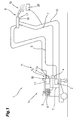
- a steam cutting machine 1 having a base apparatus 1a for a water vapor cutting method.
- the base unit 1a comprises a power source 2, a control device 3 and a blocking element 4 associated with the control device 3.
- the blocking element 4 is connected to a container 5 and a steam plasma burner 6 comprising a burner handle 6a and a burner body 6b via a supply line 7 the steam plasma burner 6 can be supplied with a liquid 8 arranged in the container 5.
- the supply of the steam plasma burner 6 with electrical energy via lines 9, 10 from the power source. 2
- a cooling circuit 11 For cooling the steam plasma burner 6 this is connected via a cooling circuit 11 at best with the interposition of a flow monitor 12 with a liquid container 13.
- the cooling circuit 11 can be started by the control device 3 and thus a cooling of the burner 6 via the cooling circuit 11 can be achieved.
- the burner 6 is connected via cooling lines 14, 15 with the liquid container 13.
- the base unit 1a may have an input and / or display device 16, via which the most different parameters or operating modes of the steam cutting device 1 can be set and displayed.
- the parameters set via the input and / or display device 16 become the control device 3 forwarded, which controls the individual components of the steam cutting device 1 accordingly.
- the steam plasma burner 6 can have at least one operating element 17, in particular a pushbutton 18.
- the user can notify by activating and / or deactivating the button 18 of the control device 3 from the burner 6 that a steam cutting process should be started or performed.
- presettings can be made, for example, at the input and / or display device 16, in particular that the material to be cut, the liquid used and, for example, characteristics of the current and the voltage are predefined.
- further operating elements can be arranged on the burner 6, via which one or more operating parameters of the steam cutting device 1 are set by the burner 6.
- these controls can be connected directly via lines or via a bus system to the base unit 1a, in particular the control device 3.
- the control device 3 activates after pressing the button 18, the individual components required for the steam cutting process. For example, first a pump (not shown), the blocking element 4 and the current source 2 are driven, whereby a supply of the burner 6 with the liquid 8 and electrical energy is introduced. Subsequently, the control device 3 activates the cooling circuit 11, so that a cooling of the burner 6 is made possible. By supplying the burner 6 with the liquid 8 and with energy, in particular with current and voltage, the liquid 8 is now in the burner 6 in a gas 19, in particular in plasma, converted at high temperature, so that by the burner from the sixth outflowing gas 19, a cutting process on a workpiece 20 can be performed.
- the Fig. 2a and 2b show schematic representations of a steam plasma burner 6 according to the invention, in particular the burner nozzle 6b, in the idle state and in the operating state.
- the steam plasma burner 6 has a housing 21 in which a cathode 22 is arranged, which is connected to the power source 2.
- the anode 24 formed as a nozzle 23 is connected to the positive pole of the power source 2.
- the axially displaceable cathode 22 according to the invention is pressed against the nozzle 23. In this mode, no arc can be ignited between the cathode 22 and the anode 24 because of a short circuit.
- the heating device 25 contained in the steam plasma burner 6 for evaporating the water can already be switched on, so that the working medium is already preheated.
- a non-transmitted arc is in accordance with Fig. 2b switched on the supply of the working fluid in the present case, the liquid 8, whereby the axially displaceable cathode 22 lifts from the nozzle 23 and ignited in the presence of a corresponding current, an arc between the cathode 22 and the anode 24.
- the evaporated water in the heater is passed into the combustion chamber 27, where it serves as a medium for a plasma jet.
- the plasma jet is forced out through the opening 25 in the nozzle 23 and, because of its high energy density, can be used for cutting but also for joining workpieces 20.
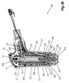
- Fig. 3a and 3b show an embodiment of a steam plasma burner 6, in particular burner insert, in a sectional view.
- the water vapor plasma burner 6 is at rest, where the cathode 22 is pressed against the anode 23 formed as a nozzle 23.
- the steam plasma burner comprises a housing 21, a heater 26, a combustion chamber 27, in which the vaporized liquid 8 is formed as a medium for the plasma jet, which emerges through the outlet opening 25 of the nozzle 23.
- the cathode 22 is connected to a cathode holder 28, preferably via a screw thread 29.
- the cathode holder 28 is pressed against the nozzle 23 via a spring 30 (shown in dashed lines).
- the steam plasma burner 6 is supplied with the liquid 8.
- the cathode 22 is designed to be axially displaceable with the cathode holder 28.
- the liquid supply line 32 is available the cathode holder 28 in such a way that when the liquid is supplied, the cathode 22 is lifted from the nozzle 23, so that an arc between the cathode 22 and the anode 24 can be ignited. This happens because the liquid 8 is guided by the liquid supply line 32 into a space around the cathode holder 28, which is bounded by a piston element 31. By the water pressure, the piston member 31 is moved together with the cathode holder 28 and the cathode 22 against the force of the spring 30 to the rear, as in Fig. 3b shown.
- the liquid 8 then passes via a cooling channel 33, which is preferably arranged spirally around the cathode holder 28, to a deflecting element 34, which is designed as a sealing ring 35.
- the sealing ring 35 also allows a centered mounting of the axially displaceable cathode holder 28.
- the liquid 8 is returned to the heater 26, where it is evaporated in a spiral channel 37. Due to the helical arrangement of the channel 37, the vaporized liquid 8 in an annulus 38, which merges into the combustion chamber 27, swirled.
- the plasma-capable medium is formed by the arc between the cathode 22 and the anode 24 to a plasma jet, which emerges via the outlet opening 25 of the nozzle.
- the thread 29 for connecting the cathode 22 to the cathode holder 28 is formed as long as possible. So that the cathode 22 is not screwed too far into the cathode holder 28, there is a stop flange 39 at the cathode 22.
- the cathode 22 may be made of copper or a copper alloy at best with a ceramic coating.
- an anti-rotation protection can be arranged, which can be formed, for example, by an axis 40 in a transverse hole 41.
- the nozzle 23 forms a further wearing part which can be exchanged, for example via a thread 42, with the housing 21 or another. Part of the steam plasma burner 6 may be connected. About a sealing ring 43 is a seal of the Nozzle 23 opposite the combustion chamber 27. At the nozzle 23, a spacer 44 may be arranged, which is arranged around the outlet opening 25 and the nozzle 23 from damage by contact of the workpiece 20 (not shown) protects.
- the spacer 44 which may be formed by a clip-on wire hanger or an attachable protective sleeve, is preferably formed from or coated with an electrically insulating material.
- a circuit breaker 45 may be arranged, which is operable in a properly arranged housing 21. This ensures that operation of the steam plasma burner 6 is possible only when the housing 21 is properly fastened. As a result, injuries are effectively prevented by, for example, touching the heater 26.
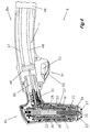
- Fig. 4 is now the entire steam burner 6, so the burner handle 6a and the burner body 6b, shown schematically and partially cut, wherein schematically the connection of a hose assembly 46, in which all lines are summarized, indicated.
- a closed cooling circuit 11 has been created in the burner handle 6a by connecting the cooling circuit feed line 47 to the cooling circuit return line 48, for example via a connecting element 49.
- the connecting element 49 has a bypass line 50, which is connected to the liquid supply line 32 in the burner body 6b, as indicated schematically.
- the bypass line 50 preferably has a smaller cross section than the cooling circuit feed line 47 and the cooling circuit return line 48, so that only a small proportion of liquid 8 is taken from the closed cooling circuit 11 in the burner handle 6a.
- a corresponding element or valve in the connecting element 49 is arranged, via which the amount of liquid to be removed can be adjusted electronically or mechanically, so that only a certain amount or a certain volume is passed into the burner body 6b.
- This configuration of the steam burner 6 now ensures that the user finds optimal cooling of the burner handle 6a and thus it can not happen that the heat transferred back from the burner body 6b heats the burner handle 6a to such an extent that the user can cause burns Handle of the torch handle 6a becomes so hot that the user can no longer pick it up.
- a much higher flow velocity in the cooling circuit is made possible because a larger cross-section of the cooling circuit supply line 47 and the cooling circuit return line 48 can be used as if the cooling circuit 11 would be performed on the burner body 6b, as in the burner body 6a less space is available. This can also be transported away more heat returned.
- this also ensures that when terminating a cutting process, the liquid 8 can be better recycled from the burner body 6b, as a Durckabfall arises and thus the liquid 8 is automatically withdrawn into the cooling circuit, ie, that when finishing the process, the pressure in the Cooling circuit inlet 47 and cooling circuit return line 48 is reduced, but in the burner body 6b, in particular in the liquid supply 32 due to the smaller cross section is still upright, so that the liquid 8 from the burner body 6b, in particular the liquid supply line 32, now in the cooling circuit 11, ie in the cooling circuit supply line 47 or cooling circuit return line 48, flows back and the hot liquid 8 is immediately removed via the cooling circuit 11 in the burner handle 6a.
- overheating of the torch body 6b after completion of the cutting process is prevented.
- bypass line 50 may have the same cross-section or diameter as the cooling circuit feed line 47 and the cooling circuit return line 48, since in the burner body 6b, in particular in the liquid feed line 32, a reduction in diameter or diameter reduction is performed, so that only as much liquid 8 to the combustion chamber 27, which is necessary for a cutting or welding process, wherein a Control of the amount of liquid 8, however, can be done via the pressure.
- the button 18 is designed as a safety switch 51, which ensures that when storing the steam burner 6, this safety switch 51 can not be activated.
- the safety switch 51 has a safety bar 52, which is arranged via a switching element 53.
- the safety latch 52 is a release device, which may be executed for example by a micro-switch (not shown), activated, whereby a signal is sent to the control device 3 by pressing the switching element 53.
- a release device ensures that only when you press the safety bar 52, the switching element 53 can be activated so that when a broken safety bar 52, the switching element 53 can not be activated.
- the cathode 22 is designed accordingly, so that the heat from the region of the combustion chamber 27 can be passed into the underlying region of the cathode holder 28.
- the cathode 22 has a plane or planar end face which, when screwed into the cathode holder 28, preferably has a full surface connection with the material of the cathode holder 28. This ensures that the rear stop of the cathode 22 with the cathode holder 28 is used for optimal heat dissipation and thus more heat energy via the screw thread 29 and the rear stop of the cathode 22 can be discharged.
- the cathode holder 28 has a coating, in particular a ceramic coating with additional sealing layer, whereby an even better heat dissipation from the cathode holder 28 is given to the liquid 8 of the parallel running cooling channel.
- the sealing layer is formed of resin base, whereby high temperature resistance is given.
- the Kermik layer preferably has a thickness of between 100 ⁇ m and 400 ⁇ m, in particular 200 ⁇ m.
- the surface of the ceramic coating may have a certain structure, in particular the largest possible surface roughness (roughness depth), so that the surface is enlarged and thus more heat can be dissipated.
- a roughness depth in the region of the seal of the cathode holder 28, a roughness depth of 0.2 .mu.m to 1 .mu.m, preferably 0.5 .mu.m, on, so that a permanent seal is given.
- this at the threaded neck has a cylindrical portion which is between 2mm to 5mm in length, and whose outer diameter corresponds to the inner diameter of the screw thread 29 in the cathode holder 28.
- a centering and alignment is achieved, so that by a simple rotational movement and pressure, the cathode can be easily screwed into the cathode holder 28.
- the cathode 22 in the region of the thread on a centering surface which is arranged in the end region of the thread in the direction of the combustion chamber 27, that is, that the thread between the cylindrical portion and the centering surface is formed.
- the centering surface has a certain length between 2mm and 8mm, preferably 4.5mm.
- transverse hole 40 not only serves as torsion protection, but also as a defined stop when lifting the cathode 22, in particular of the cathode holder 22, is responsible.
Landscapes
- Physics & Mathematics (AREA)
- Engineering & Computer Science (AREA)
- Plasma & Fusion (AREA)
- Spectroscopy & Molecular Physics (AREA)
- Plasma Technology (AREA)
- Arc Welding Control (AREA)
Description
- Die Erfindung betrifft einen Wasserdampfplasmabrenner mit einem Brennergriff und einem Brennerkörper, wobei im Brennerkörper eine Flüssigkeitszuleitung, eine Heizeinrichtung, eine Brennkammer, eine mit dem Kathodenhalter verbundene Kathode und eine als Düse ausgebildete Anode mit einer Austrittsöffnung angeordnet ist.
- Bei Wasserdampfplasmabrennern der gegenständlichen Art wird über eine Stromquelle ein Lichtbogen zwischen einer negativ gepolten Kathode und einer positiv gepolten Anode, welche als Düse an der Spitze des Brenners ausgebildet ist, gezündet. Flüssigkeit bzw. Wasser wird von einem Tank über eine entsprechende Leitung zum Brenner geführt und dort mittels einer Heizeinrichtung zu Dampf erhitzt und über entsprechende Kanäle in die Brennkammer geleitet, wo es als Plasma-bildendes Medium ein Plasma erzeugt. Der Plasmastrahl tritt stromlos aus der Düse aus, wo er aufgrund der hohen Energiedichte zum Aufschmelzen von Werkstücken verwendet werden kann. Da der Plasmastrahl stromlos aus der Düse des Brenners austritt und kein Lichtbogen zwischen der Düse zu dem zu bearbeitenden Werkstück erzeugt wird, können auch nicht leitende Werkstoffe thermisch bearbeitet werden. Neben dem Schneiden von Werkstücken kann mittels eines Wasserdampfplasmabrenners auch ein Verbinden von Werkstücken durchgeführt werden.
- Beispielsweise beschreibt die
DE 100 08 255 A1 einen Wasserdampfplasmabrenner, der speziell ausgebildet ist, um niedrigere Energieniveaus an der Plasmabrennerspitze für andere Anwendungen zu erzielen. - Ein Lichtbogenplasmabrenner der gegenständlichen Art, bei dem der Behälter für das Arbeitsfluid im Brenner integriert ist, wird in der
EP 0 640 426 A1 beschrieben. - Die
EP 1 050 200 B1 beschreibt einen Wasserdampfplasmabrenner, der für eine möglichst lange Laufzeit für einen Schneidvorgang speziell ausgebildet ist. - Die
US 3 242 305 A beschreibt einen Plasmabrenner, welcher einen axial verschiebbare Elektrode aufweist. Durch das Abheben der Elektrode von der Düse kann eine Kompaktzündung vorgenommen werden. - Die
JP 2004 268089 - Die Aufgabe der vorliegenden Erfindung besteht in der Schaffung eines oben genannten Wasserdampfplasmabrenners, der eine möglichst exakte Zündung des Lichtbogens zulässt und für einen optimalen Betrieb möglichst gut gekühlt werden kann.
- Gelöst wird die erfindungsgemäße Aufgabe durch einen oben genannten Wasserdampfplasmabrenner, bei dem die im Brennerkörper angeordnete Flüssigkeitszuleitung zur Brennkammer derart ausgebildet ist, dass die zugeführte Flüssigkeit zuerst entlang des Kathodenhalters über einen Kühlkanal geführt ist, und anschließend entlang der Heizeinrichtung zur Brennkammer verläuft. Durch diese Maßnahme wird ein Wasserdampfplasmabrenner geschaffen, dessen Kathode durch die Flüssigkeit bzw. das Wasser besser gekühlt wird. Durch die Wärmeaufnahme der Flüssigkeit wird in der Folge weniger Energie für die Verdampfung benötigt.
- Vorteilhafterweise ist um den Kathodenhalter ein von einem Kolbenelement begrenzter Raum angeordnet, der mit der Flüssigkeitszuleitung verbunden ist, so dass durch Zufuhr von Flüssigkeit der Raum gefüllt wird und der Kathodenhalter mit der Kathode von der Düse abhebt.
- Um eine annähernde Abdichtung der Düse im Ruhezustand des Plasmabrenners zu erzielen und Beschädigungen der Kathode oder Düse durch eine Verteilung der Kräfte zu vermeiden, stimmt die Form der Spitze der Kathode vorzugsweise mit der Form der Innenseite der Düse überein. Bei der Formgestaltung werden scharfe Kanten oder Ecken vorzugsweise vermieden.
- Da die Kathode und der Kathodenhalter axial verschiebbar ausgebildet sind, werden am Kathodenhalter bevorzugterweise Dichtungsringe angeordnet. Diese Dichtungsringe sind aus elastischem Material gebildet, welches die bei Wasserdampfplasmabrennern üblichen Temperaturen aushalten, beispielsweise aus Silikonverbundwerkstoffen oder Teflonverbundwerkstoffen. Über den oder die Dichtungsringe kann auch eine Zentrierung des Kathodenhalters im umgebenden Zylinder des Wasserdampfplasmabrenners erfolgen.
- Um eine Verbindung der stromführenden Kathode mit anderen Bauelementen des Wasserdampfplasmabrenners zu verhindern, weist der Kathodenhalter eine elektrisch isolierende Beschichtung auf. Dabei soll die Beschichtung eine gute elektrische Isolierung aber auch eine gute Wärmeleitung zum Abführen der entstehenden Wärme aufweisen. Zusätzlich erfolgt bevorzugt eine Versiegelung der isolierenden Beschichtung.
- Die Kathode des Wasserdampfplasmabrenners besteht gemäß einem weiteren Merkmal der Erfindung aus Kupfer oder einer Kupferlegierung.
- Um die Kathode vor den auftretenden hohen Temperaturen zu schützen, kann diese zumindest teilweise mit einer elektrischen Isolation, insbesondere einer Keramikbeschichtung, versehen sein.
- Um einen raschen Tausch der Kathode zu ermöglichen, ist diese vorzugsweise mit dem Kathodenhalter über ein Gewinde verbunden. Um einen möglichst guten Wärmeübergang von der Kathode zum Kathodenhalter zu erzielen ist das Gewinde relativ lang ausgebildet.
- Vorzugsweise weist die Kathode einen Anschlagflansch auf, der verhindert, dass die Kathode zu weit in den Kathodenhalter gedreht wird, was zu einer Zerstörung des Gewindes führen könnte. Darüber hinaus wird die Verbindungsstelle zwischen Kathode und Kathodenhalter über den Anschlagflansch abgedichtet und verhindert ein Eindringen des Arbeitsmediums.
- Um zu verhindern, dass sich der Kathodenhalter beim Montieren bzw. Demontieren der Kathode verdreht, ist am Kathodenhalter vorzugsweise eine Einrichtung zum Schutz vor Verdrehung angeordnet, welche beispielsweise durch eine Achse gebildet ist, welche in einem Querloch des Kathodenhalters angeordnet ist.
- Um eine ausreichende Kühlung des Wasserdampfplasmabrenners zu erzielen, ist der Kathodenhalter von zumindest einem Kühlkanal umgeben, welcher mit der Flüssigkeitszuleitung in Verbindung steht, so dass eine Flüssigkeit, insbesondere Wasser bzw. ein entsprechendes Wassergemisch, als Kühlmedium verwendbar ist. Dabei wird die Flüssigkeit von der Flüssigkeitszuleitung in eine Kammer um den Kathodenhalter gefördert und entlang des zumindest einen Kühlkanals um den Kathodenhalter befördert, so dass der Kathodenhalter durch die Flüssigkeit gekühlt wird. Da als Kühlmedium die Flüssigkeit des Wasserdampfplasmabrenners verwendet wird, braucht kein eigener Kühlkreislauf mit einem eigenen Kühlmedium angeordnet werden.
- Der zumindest eine Kühlkanal verläuft um den Kathodenhalter entlang, vorzugsweise spiralförmig. Durch diese Führung des Kühlkanals wird eine gleichmäßige Verteilung des Wassers um den Kathodenhalter gewährleistet. Zusätzlich zum Kühlkanal ist es von Vorteil, wenn ein schmaler Ringspalt um den gesamten Kathodenhalter frei bleibt, in den das Kühlmedium eindringen kann. Dadurch wird eine sichere Benetzung der gesamten Oberfläche des Kathodenhalters erzielt und lokale Überhitzungen des Kathodenhalters vermieden.
- Um den Wasserdampfplasmabrenner in seiner Baugröße kompakt zu halten, wird die Flüssigkeit, welche zur Kühlung des Kathodenhalters diesen umströmt hat, über einen Rückführungskanal wieder zur Heizeinrichtung zurückgeführt.
- Die Heizeinrichtung weist vorzugsweise einen spiralförmigen Kanal zur Durchführung der Flüssigkeit auf, in welchem diese verdampft wird. Der spiralförmige Kanal hat den Vorteil, dass die in der meist durch eine elektrische Heizung ausgebildeten Heizeinrichtung verdampfte Flüssigkeit verwirbelt wird und in diesem verwirbelten Zustand in die Brennkammer gelangt.
- Um eine Inbetriebnahme des Wasserdampfplasmabrenners bei nicht ordnungsgemäß angeordnetem Gehäuse zu verhindern, kann ein Schutzschalter vorgesehen sein, der nur bei ordnungsgemäß angeordnetem Gehäuse betätigbar ist. Dieser Schutzschalter kann durch einen Mikrotaster gebildet sein, der durch das ordnungsgemäß aufgeschraubte oder aufgesteckte Gehäuse betätigt wird. Erst bei geschlossenem Schutzschalter wird eine Zufuhr der Flüssigkeit und ein Einschalten der elektrischen Versorgung ermöglicht.
- Um eine Kühlung auch der Düse des Wasserdampfplasmabrenners zu ermöglichen, kann die Düse auch Kühlkanäle zur Führung eines Kühlfluids aufweisen. Eine gewisse Kühlung der Düse kann auch dadurch erfolgen, dass die Düse über ein Gewinde mit dem Gehäuse verbunden ist. Somit kann die an der Düse entstehende Wärme über das Gewinde an das Gehäuse abgeführt werden.
- Um die Düse vor mechanischer Beschädigung zu schützen und einen gewissen Mindestabstand zum Werkstück einzuhalten, kann an der Düse ein Abstandhalter angeordnet sein.
- Dabei ist der Abstandhalter vorzugsweise ringförmig um die Austrittsöffnung angeordnet.
- Der Abstandhalter kann auch einstückig mit der Düse hergestellt sein.
- Ebenso kann der Abstandhalter durch einen aufsteckbaren Drahtbügel gebildet sein. Dies bietet eine besonders einfache und kostengünstige Realisierungsmöglichkeit. Ebenso kann der Abstandhalter durch eine aufsteckbare Schutzhülse gebildet sein.
- Der Abstandhalter ist aus elektrisch isolierendem Material gebildet oder mit einem solchen beschichtet. Dadurch ist die stromführende Anode bei einem nicht übertragenen Lichtbogen von der Umgebung isoliert.
- Weitere Merkmale gehen aus der obigen Beschreibung des Wasserdampfplasmabrenners hervor.
- Die vorliegende Erfindung wird anhand der beigefügten Zeichnungen näher erläutert. Darin zeigen:
-
Fig. 1 eine schematische Darstellung eines Wasserdampf-Schneidgeräts; -
Fig. 2a und 2b schematische Darstellungen eines Wasserdampfplasmabrenners mit einer erfindungsgemäß axial verschiebbaren Kathode im Ruhezustand und in Betriebsstellung; -
Fig. 3a und3b Schnittbilder einer Ausführungsform eines Wasserdampfplasmabrenners im Ruhezustand und im Betriebszustand; und -
Fig. 4 eine schematische Darstellung des Wasserdampfplasmabrenners mit dem Brennergriff und dem Brennerkörper. - In
Fig. 1 ist ein Wasserdampf-Schneidgerät 1 mit einem Grundgerät 1a für ein Wasserdampf-Schneidverfahren gezeigt. Das Grundgerät 1a umfasst eine Stromquelle 2, eine Steuervorrichtung 3 und ein der Steuervorrichtung 3 zugeordnetes Sperrelement 4. Das Sperrelement 4 ist mit einem Behälter 5 und einem Wasserdampfplasmabrenner 6, der einen Brennergriff 6a und einen Brennerkörper 6b umfasst, über eine Versorgungsleitung 7 verbunden, so dass der Wasserdampfplasmabrenner 6 mit einer im Behälter 5 angeordneten Flüssigkeit 8 versorgt werden kann. Die Versorgung des Wasserdampfplasmabrenners 6 mit elektrischer Energie erfolgt über Leitungen 9, 10 von der Stromquelle 2. - Zum Kühlen des Wasserdampfplasmabrenners 6 ist dieser über einen Kühlkreislauf 11 allenfalls unter Zwischenschaltung eines Strömungswächters 12 mit einem Flüssigkeitsbehälter 13 verbunden. Bei der Inbetriebnahme des Brenners 6 bzw. des Grundgerätes 1a kann der Kühlkreislauf 11 von der Steuervorrichtung 3 gestartet und somit eine Kühlung des Brenners 6 über den Kühlkreislauf 11 erreicht werden. Zur Bildung des Kühlkreislaufs 11 wird der Brenner 6 über Kühlleitungen 14, 15 mit dem Flüssigkeitsbehälter 13 verbunden.
- Weiters kann das Grundgerät 1a eine Eingabe- und/oder Anzeigevorrichtung 16 aufweisen, über welche die unterschiedlichsten Parameter bzw. Betriebsarten des Wasserdampf-Schneidgerätes 1 eingestellt und angezeigt werden können. Die über die Eingabe- und/oder Anzeigevorrichtung 16 eingestellten Parameter werden an die Steuervorrichtung 3 weitergeleitet, welche die einzelnen Komponenten des Wasserdampf-Schneidgerätes 1 entsprechend ansteuert.
- Weiters kann der Wasserdampfplasmabrenner 6 zumindest ein Bedienungselement 17, insbesondere einen Taster 18, aufweisen. Über das Bedienungselement 17, insbesondere den Taster 18, kann der Benutzer durch Aktivieren und/oder Deaktivieren des Tasters 18 der Steuervorrichtung 3 vom Brenner 6 aus mitteilen, dass ein Wasserdampf-Schneidverfahren gestartet bzw. durchgeführt werden soll. Des Weiteren können an der Eingabe- und/oder Anzeigevorrichtung 16 beispielsweise Voreinstellungen getroffen werden, insbesondere, dass das zu schneidende Material, die verwendete Flüssigkeit und beispielsweise Kennlinien des Stromes und der Spannung vordefiniert werden. Selbstverständlich können weitere Bedienelemente am Brenner 6 angeordnet sein, über die ein oder mehrere Betriebsparameter des Wasserdampf-Schneidgerätes 1 vom Brenner 6 aus eingestellt werden. Hierzu können diese Bedienelemente direkt über Leitungen oder über ein Bussystem mit dem Grundgerät 1a, insbesondere der Steuervorrichtung 3, verbunden sein.
- Die Steuervorrichtung 3 aktiviert nach dem Betätigen des Tasters 18 die einzelnen für das Wasserdampf-Schneidverfahren benötigten Komponenten. Beispielsweise werden zuerst eine Pumpe (nicht dargestellt), das Sperrelement 4 sowie die Stromquelle 2 angesteuert, wodurch eine Versorgung des Brenners 6 mit der Flüssigkeit 8 sowie mit elektrischer Energie eingeleitet wird. Anschließend aktiviert die Steuervorrichtung 3 den Kühlkreislauf 11, so dass eine Kühlung des Brenners 6 ermöglicht wird. Durch die Versorgung des Brenners 6 mit der Flüssigkeit 8 und mit Energie, insbesondere mit Strom und Spannung, wird nunmehr im Brenner 6 die Flüssigkeit 8 in ein Gas 19, insbesondere in Plasma, mit hoher Temperatur umgewandelt, so dass durch das aus dem Brenner 6 ausströmende Gas 19 ein Schneidprozess an einem Werkstück 20 durchgeführt werden kann.
- Die
Fig. 2a und 2b zeigen schematische Darstellungen eines erfindungsgemäßen Wasserdampfplasmabrenners 6, insbesondere der Brennerdüse 6b, im Ruhezustand und im Betriebszustand. Der Wasserdampfplasmabrenner 6 weist ein Gehäuse 21 auf, in dem eine Kathode 22 angeordnet ist, die mit der Stromquelle 2 verbunden ist. Die als Düse 23 ausgebildete Anode 24 ist mit dem positiven Pol der Stromquelle 2 verbunden. Im Ruhezustand gemäßFig. 2a wird die erfindungsgemäß axial verschiebbare Kathode 22 an die Düse 23 gepresst. In diesem Modus kann zwischen der Kathode 22 und der Anode 24 kein Lichtbogen gezündet werden, da ein Kurzschluss besteht. Die im Wasserdampfplasmabrenner 6 enthaltene Heizeinrichtung 25 zum Verdampfen des Wassers kann bereits eingeschaltet werden, so dass das Arbeitsmedium bereits vorgeheizt wird. - Zum Zünden eines Lichtbogens zwischen der Kathode 22 und der Anode 24, also einen nicht übertragenen Lichtbogen wird gemäß
Fig. 2b die Zufuhr des Arbeitsfluids im gegenständlichen Fall der Flüssigkeit 8 eingeschaltet, wodurch sich die axial verschiebbare Kathode 22 von der Düse 23 abhebt und bei Vorhandensein eines entsprechenden Stromes ein Lichtbogen zwischen der Kathode 22 und der Anode 24 gezündet. Das in der Heizeinrichtung verdampfte Wasser wird in die Brennkammer 27 geleitet, wo es als Medium für einen Plasmastrahl dient. Der Plasmastrahl wird durch die Öffnung 25 in der Düse 23 herausgepresst und kann aufgrund seiner hohen Energiedichte zum Schneiden aber auch Verbinden von Werkstücken 20 eingesetzt werden. -
Fig. 3a und3b zeigen eine Ausführungsform eines Wasserdampfplasmabrenners 6, insbesondere Brennereinsatz, in geschnittener Darstellung. GemäßFig. 3a befindet sich der Wasserdampfplasmabrenner 6 im Ruhezustand, wo die Kathode 22 an die als Düse 23 ausgebildete Anode 24 gepresst wird. Der Wasserdampfplasmabrenner umfasst ein Gehäuse 21, eine Heizeinrichtung 26, eine Brennkammer 27, in der die verdampfte Flüssigkeit 8 als Medium für den Plasmastrahl gebildet wird, der durch die Austrittsöffnung 25 der Düse 23 austritt. Die Kathode 22 ist mit einem Kathodenhalter 28, vorzugsweise über ein Schraubgewinde 29, verbunden. Der Kathodenhalter 28 wird über eine Feder 30 (strichliert gezeigt) gegen die Düse 23 gepresst. Über eine Flüssigkeitszuleitung 32 wird der Wasserdampfplasmabrenner 6 mit der Flüssigkeit 8 versorgt. Die Kathode 22 ist mit dem Kathodenhalter 28 axial verschiebbar ausgebildet. Die Flüssigkeitszuleitung 32 steht mit dem Kathodenhalter 28 derart in Verbindung, dass bei Flüssigkeitszufuhr die Kathode 22 von der Düse 23 abgehoben wird, so dass ein Lichtbogen zwischen der Kathode 22 und der Anode 24 gezündet werden kann. Dies geschieht dadurch, dass die Flüssigkeit 8 von der Flüssigkeitszuleitung 32 in einen Raum um den Kathodenhalter 28 geleitet wird, der von einem Kolbenelement 31 begrenzt wird. Durch den Wasserdruck wird das Kolbenelement 31 zusammen mit dem Kathodenhalter 28 und der Kathode 22 gegen die Kraft der Feder 30 nach hinten verschoben, wie inFig. 3b dargestellt. - Die Flüssigkeit 8 gelangt anschließend über einen Kühlkanal 33, der vorzugsweise spiralförmig um den Kathodenhalter 28 entlang angeordnet ist, zu einem Umlenkelement 34, welches als Dichtring 35 ausgebildet ist. Der Dichtring 35 ermöglicht auch eine zentrierte Lagerung des axial verschiebbaren Kathodenhalters 28. Über einen Rückführungskanal 36 wird die Flüssigkeit 8 zur Heizeinrichtung 26 zurückgeführt, wo diese in einem spiralförmigen Kanal 37 verdampft wird. Durch die spiralförmige Anordnung des Kanals 37 wird die verdampfte Flüssigkeit 8 in einem Ringraum 38, der in die Brennkammer 27 übergeht, verwirbelt. Das plasmafähige Medium wird durch den Lichtbogen zwischen der Kathode 22 und der Anode 24 zu einem Plasmastrahl, der über die Austrittsöffnung 25 der Düse austritt. Um eine optimale Wärmeabfuhr von der Kathode 22 zum Kathodenhalter 28 zu garantieren, ist das Gewinde 29 zur Verbindung der Kathode 22 mit dem Kathodenhalter 28 möglichst lang ausgebildet. Damit die Kathode 22 nicht zu weit in den Kathodenhalter 28 eingeschraubt wird, befindet sich ein Anschlagflansch 39 an der Kathode 22. Die Kathode 22 kann aus Kupfer oder einer Kupferlegierung allenfalls mit einer Keramikbeschichtung hergestellt sein. Um den Kathodenhalter 28 beim Auf- oder Abschrauben der Kathode 22 vor Verdrehen zu sichern, kann ein Verdrehschutz angeordnet sein, welcher beispielsweise durch eine Achse 40 in einem Querloch 41 gebildet sein kann.
- Die Düse 23 bildet einen weiteren Verschleißteil, der zum Wechseln beispielsweise über ein Gewinde 42 mit dem Gehäuse 21 oder einem anderen. Teil des Wasserdampfplasmabrenners 6 verbunden sein kann. Über einen Dichtring 43 erfolgt eine Abdichtung der Düse 23 gegenüber der Brennkammer 27. An der Düse 23 kann ein Abstandhalter 44 angeordnet sein, der um die Austrittsöffnung 25 angeordnet ist und die Düse 23 vor Beschädigung durch Berührung des Werkstücks 20 (nicht dargestellt) schützt. Der Abstandhalter 44, der durch einen aufsteckbaren Drahtbügel oder eine aufsteckbare Schutzhülse gebildet sein kann, ist vorzugsweise aus elektrisch isolierendem Material gebildet oder mit einem solchen beschichtet.
- Schließlich kann im Wasserdampfplasmabrenner 6 ein Schutzschalter 45 angeordnet sein, der bei ordnungsgemäß angeordnetem Gehäuse 21 betätigbar ist. Dadurch wird gewährleistet, dass nur bei ordnungsgemäß befestigtem Gehäuse 21 ein Betrieb des Wasserdampfplasmabrenners 6 möglich wird. Dadurch werden Verletzungen beispielsweise durch Berühren der Heizeinrichtung 26 wirkungsvoll verhindert.
- In
Fig. 4 ist nunmehr der gesamte Wasserdampfbrenner 6, also der Brennergriff 6a und der Brennerkörper 6b, schematisch und teilweise geschnitten dargestellt, wobei schematisch der Anschluss eines Schlauchpaketes 46, in dem sämtliche Leitungen zusammengefasst sind, angedeutet. - Erfindungsgemäß ist nunmehr ersichtlich, dass im Brennergriff 6a ein geschlossener Kühlkreislauf 11 durch verbinden der Kühlkreiszuleitung 47 mit der Kühlkreisrückleitung 48 beispielsweise über ein Verbindungselement 49 geschaffen wurde. Zusätzlich weißt das Verbindungselement 49 eine Bypass-Leitung 50 auf, die mit der Flüssigkeitszuleitung 32 im Brennerkörper 6b verbunden ist, wie schematisch angedeutet. Die Bypass-Leitung 50 weißt dabei bevorzugt einen geringeren Querschnitt auf, als die Kühlreiszuleitung 47 und Kühlkreisrückleitung 48, so dass nur ein geringer Anteil von Flüssigkeit 8 vom geschlossenen Kühlkreislauf 11 im Brennergriff 6a entnommen wird. Selbstverständlich ist es möglich, dass hierzu ein entsprechendes Element bzw. Ventil im Verbindungselement 49 angeordnet wird, über das die zu entnehmende Flüssigkeitsmenge elektronisch oder mechanisch eingestellt werden kann, so dass nur eine bestimmte Menge bzw. ein bestimmtes Volumen in den Brennerkörper 6b geleitet wird.
- Durch diese Ausbildung des Wasserdampfbrenners 6 wird nun erreicht, dass der Benutzer eine optimale Kühlung des Brennergriffes 6a vorfindet und es somit nicht passieren kann, dass die vom Brennerkörper 6b zurückübertragene Wärme den Brennergriff 6a soweit erhitzt, dass sich der Benutzer Verbrennungen zuführen kann bzw. die Griffschale des Brennergriffes 6a so heiß wird, dass der Benutzer sie nicht mehr in die Hand nehmen kann. Gleichzeitig wird dadurch auch erreicht, dass eine wesentlich höhere Durchflussgeschwindigkeit im Kühlkreislauf ermöglicht wird, da ein größerer Querschnitt der Kühlkreiszuleitung 47 und der Kühlkreisrückleitung 48 verwendet werden kann, als wenn der Kühlkreislauf 11 über den Brennerkörper 6b geführt werden würde, da im Brennerkörper 6a weniger Platz vorhanden ist. Damit kann auch mehr zurückgeführte Wärme abtransportiert werden.
- Weiters wird dadurch auch erreicht, dass beim Beenden eines Schneidprozesses die Flüssigkeit 8 aus dem Brennerkörper 6b besser rückgeführt werden kann, da ein Durckabfall entsteht und somit die Flüssigkeit 8 automatisch in den Kühlkreislauf zurückgezogen wird, d.h., dass beim Beenden des Prozesses der Druck in der Kühlkreiszuleitung 47 und Kühlkreisrückleitung 48 verringert wird, wobei jedoch im Brennerkörper 6b, insbesondere in der Flüssigkeitszuleitung 32 aufgrund des geringeren Querschnittes noch aufrecht ist, sodass die Flüssigkeit 8 vom Brennerkörper 6b, insbesondere der Flüssigkeitszuleitung 32, nun in den Kühlkreislauf 11, also in die Kühlkreiszuleitung 47 bzw. Kühlkreisrückleitung 48, zurück fließt und die heiße Flüssigkeit 8 sofort über den Kühlkreislauf 11 im Brennergriff 6a abtransportiert wird. Somit wird eine Überhitzung des Brennerkörpers 6b nach Beendigung des Schneidprozesses verhindert.
- Es ist auch möglich, dass die Bypass-Leitung 50 den gleichen Querschnitt bzw. Durchmesser wie die Kühlkreiszuleitung 47 und die Kühlkreisrückleitung 48 aufweisen kann, da im Brennerkörper 6b, insbesondere in der Flüssigkeitszuleitung 32, eine Querschnittsverringerung bzw. Durchmesserverringerung, durchgeführt wird, sodass nur soviel Flüssigkeit 8 zur Brennkammer 27, was für einen Schneid- bzw. Schweißprozess notwendig ist, wobei eine Regelung der Menge der Flüssigkeit 8 jedoch über den Druck erfolgen kann.
- Der Vollständigkeit halber wird noch erwähnt, dass zusätzliche Leitungen, wie die Stromleitungen für die Anode 24 und die Kathode 22 sowie eventuelle Steuerleitungen, der Übersicht halber nicht dargestellt wurden.
- Weiters ist in
Fig. 4 noch ersichtlich, dass der Taster 18 als Sicherheitsschalter 51 ausgebildet ist, wodurch sichergestellt ist, dass beim Ablegen des Wasserdampfbrenners 6 dieser Sicherheitsschalter 51 nicht aktiviert werden kann. Hierzu weist der Sicherheitsschalter 51 einen Sicherheitsbügel 52 auf, der über ein Schaltelement 53 angeordnet ist. Der Benutzer muss zur Betätigung des Schaltelementes 53 zuerst den Sicherheitsbügel 52 nach unten bzw. nach vor drücken, so dass er anschließend mit dem Finger zum Schaltelement 53 gelangen kann. Durch die Bewegung des Sicherheitsbügels 52 wird eine Freigabevorrichtung, die beispielsweise durch einen Mikroschalter ausgeführt sein kann (nicht dargestellt), aktiviert, wodurch durch Betätigen des Schaltelementes 53 ein Signal an die Steuervorrichtung 3 übersendet wird. Durch diese Freigabevorrichtung wird sichergestellt, dass nur bei Betätigen des Sicherheitsbügels 52 das Schaltelement 53 aktiviert werden kann, so dass bei einem abgebrochenen Sicherheitsbügel 52 das Schaltelement 53 nicht aktiviert werden kann. - Grundsätzlich ist zu dem Aufbau des Wasserdampfplasmabrenners 6 noch zu erwähnen, dass die Wärmerückführung der Teile im Bereich des Austritts des Plasmastrahls 25 von besonderer Bedeutung ist, damit eine Überhitzung des Brennerkörpers 6b während des Betriebes verhindert wird. Hierzu ist beispielsweise die Kathode 22 entsprechend ausgebildet, damit die Wärme vom Bereich der Brennkammer 27 in den dahinterliegenden Bereich des Kathodenhalters 28 geleitet werden kann. Die Kathode 22 weist hierzu im Bereich des Kathodenhalters 28 eine plane bzw. ebene Stirnfläche auf, die beim Einschrauben in den Kathodenhalter 28 mit dem Material des Kathodenhalters 28 bevorzugt vollflächig in Verbindung steht. Damit wird erreicht, dass auch der hintere Anschlag der Kathode 22 mit dem Kathodenhalter 28 zur optimalen Wärmeabfuhr dient und somit mehr Wärmeenergie über das Schraubgewinde 29 und dem hinteren Anschlag der Kathode 22 abgegeben werden kann.
- Weiters weist die Kathodenhalter 28 eine Beschichtung, insbesondere eine Keramikbeschichtung mit zusätzlicher Versiegelungschicht, auf, wodurch eine noch bessere Wärmeabführ vom Kathodenhalter 28 an die Flüssigkeit 8 des parallellaufenden Kühlkanales gegeben ist. Hierzu dient die Keramikbeschichtung zur Isolation des Kathodenhalters 28 gegenüber der Flüssigkeit 8 bzw. anderen anliegenden Teilen, wogegen die Versiegelungsschicht zum Abdichten der Keramikschicht gegenüber der Flüssigkeit 8 dient, sodass keine Flüssigkeit 8 durch die Keramikschicht an den Kathodenhalter durchdringen kann. Beispielsweise wird die Versiegelungsschicht aus Harzbasis gebildet ist, wodurch eine hohe Temperaturbeständigkeit gegeben ist. Bevorzugt weist die Kermikschicht eine Dicke zwischen 100µm und 400µm, insbesondere 200µm, auf.
- Um eine noch bessere Wärmeabfuhr zu erreichen, kann die Oberfläche der Keramikbeschichtung eine bestimmte Struktur, insbesondere eine möglichst große Oberflächenrauhigkeit (Rauhtiefe), aufweisen, sodass die Oberfläche vergrößert wird und somit mehr Wärme abgegeben werden kann. Hierbei wird im Bereich der Abdichtung des Kathodenhalters 28 eine Rauhtiefe von 0,2µm bis 1µm, bevorzugt 0,5µm, auf, damit eine dauerhafte Abdichtung gegeben ist.
- Vorteilhaft ist aber auch, dass für den Tausch der Kathode 22 diese am Gewindeansatz einen zylindrischen Bereich aufweist, der zwischen 2mm bis 5mm Länge beträgt, und dessen Außendurchmesser dem Innendurchmesser des Schraubgewindes 29 im Kathodenhalter 28 entspricht. Somit wird erreicht, dass beim Ansetzen der Kathode 22 am Kathodenhalter 28 eine Zentrierung und Ausrichtung erreicht wird, sodass durch eine einfache Drehbewegung und Druck die Kathode leicht in den Kathodenhalter 28 eingeschraubt werden kann. Darüber hinaus weist die Kathode 22 im Bereich des Gewindes eine Zentrierfläche auf, die im Endbereich des Gewindes in Richtung der Brennkammer 27 angeordnet ist, d.h., dass das Gewinde zwischen dem zylindrischen Bereich und der Zentrierfläche ausgebildet ist. Die Zentrierfläche weist eine bestimmte Länge zwischen 2mm und 8mm, bevorzugt, 4,5mm, auf.
- Schließlich ist es auch möglich, dass das Querloch 40 nicht nur als Verdrehschutz dient, sonder auch als definierter Anschlag beim Abheben der Kathode 22, insbesondere des Kathodenhalter 22, zuständig ist.
Claims (17)
- Wasserdampfplasmabrenner (6) mit einem Brennergriff (6a) und einem Brennerkörper (6b), wobei im Brennerkörper (6b) eine Flüssigkeitszuleitung (32), eine Heizeinrichtung (26), eine Brennkammer (27), eine mit einem Kathodenhalter (28) verbundene Kathode (22) und eine als Düse (23) ausgebildete Anode (24) mit einer Austrittsöffnung (25) angeordnet ist, dadurch gekennzeichnet, dass die im Brennerkörper (6b) angeordnete Flüssigkeitszuleitung (32) zur Brennkammer (27) derart ausgebildet ist, dass die zugeführte Flüssigkeit (8) zuerst entlang des Kathodenhalters (28) über einen Kühlkanal (33) geführt ist, und anschließend entlang der Heizeinrichtung (26) zur Brennkammer (27) verläuft.
- Wasserdampfplasmabrenner (6) nach Anspruch 1, dadurch gekennzeichnet, dass um den Kathodenhalter (28) ein von einem Kolbenelement (31) begrenzter Raum angeordnet ist, der mit der Flüssigkeitszuleitung (32) verbunden ist, so dass durch Zufuhr von Flüssigkeit (8) der Raum gefüllt wird und der Kathodenhalter (28) mit der Kathode (22) von der Düse (23) abhebt.
- Wasserdampfplasmabrenner (6) nach Anspruch 1 oder 2, dadurch gekennzeichnet, dass die Form der Spitze der Kathode (22) mit der Form der Innenseite der Düse (23) übereinstimmt.
- Wasserdampfplasmabrenner (6) nach einem der Ansprüche 1 bis 3, dadurch gekennzeichnet, dass am Kathodenhalter (28) Dichtungsringe (35) angeordnet sind.
- Wasserdampfplasmabrenner (6) nach einem der Ansprüche 1 bis 4, dadurch gekennzeichnet, dass der Kathodenhalter (28) eine elektrisch isolierende Beschichtung und bevorzugt eine Versiegelung aufweist.
- Wasserdampfplasmabrenner (6) nach einem der Ansprüche 1 bis 5, dadurch gekennzeichnet, dass die Kathode (22) aus Kupfer oder einer Kupferlegierung besteht.
- Wasserdampfplasmabrenner (6) nach einem der Ansprüche 1 bis 6, dadurch gekennzeichnet, dass die Kathode (22) zumindest teilweise mit einer elektrischen Isolierung, insbesondere einer Keramikbeschichtung versehen ist.
- Wasserdampfplasmabrenner (6) nach einem der Ansprüche 1 bis 7, dadurch gekennzeichnet, dass die Kathode (22) mit dem Kathodenhalter (28) über ein Gewinde (29) verbunden ist.
- Wasserdampfplasmabrenner (6) nach Anspruch 8, dadurch gekennzeichnet, dass die Kathode (22) einen Anschlagflansch (39) aufweist.
- Wasserdampfplasmabrenner (6) nach einem der Ansprüche 1 bis 9, dadurch gekennzeichnet, dass am Kathodenhalter (28) eine Einrichtung zum Schutz vor Verdrehung angeordnet ist, welche beispielsweise durch eine Achse (40) gebildet ist, welche in einem Querloch (41) des Kathodenhalters (28) angeordnet ist.
- Wasserdampfplasmabrenner (6) nach einem der Ansprüche 1 bis 10, dadurch gekennzeichnet, dass der Kathodenhalter (28) von zumindest einem Kühlkanal (33) umgeben ist, welcher mit der Flüssigkeitszuleitung (32) in Verbindung steht, so dass das Wasser als Kühlmedium verwendbar ist.
- Wasserdampfplasmabrenner (6) nach Anspruch 11, dadurch gekennzeichnet, dass der zumindest eine Kühlkanal (33) um den Kathodenhalter (28) entlang, vorzugsweise spiralförmig verläuft.
- Wasserdampfplasmabrenner (6) nach einem der Ansprüche 1 bis 12, dadurch gekennzeichnet, dass ein Rückführungskanal (36) zur Rückführung der Flüssigkeit zur Heizeinrichtung (26) angeordnet ist.
- Wasserdampfplasmabrenner (6) nach einem der Ansprüche 1 bis 13, dadurch gekennzeichnet, dass die Heizeinrichtung (26) einen spiralförmigen Kanal (37) zur Durchführung der Flüssigkeit aufweist.
- Wasserdampfplasmabrenner (6) nach einem der Ansprüche 1 bis 14, dadurch gekennzeichnet, dass ein Schutzschalter vorgesehen ist, der bei ordnungsgemäß angeordnetem Gehäuse (21) betätigbar ist.
- Wasserdampfplasmabrenner (6) nach einem der Ansprüche 1 bis 15, dadurch gekennzeichnet, dass die Düse (23) Kühlkanäle zur Führung eines Kühlfluids aufweist.
- Wasserdampfplasmabrenner (6) nach einem der Ansprüche 1 bis 16, dadurch gekennzeichnet, dass die Düse (23) über ein Gewinde (42) mit dem Gehäuse (21) verbunden ist.
Applications Claiming Priority (2)
| Application Number | Priority Date | Filing Date | Title |
|---|---|---|---|
| AT0147705A AT502448B1 (de) | 2005-09-09 | 2005-09-09 | Wasserdampfplasmabrenner |
| PCT/AT2006/000366 WO2007028183A2 (de) | 2005-09-09 | 2006-09-06 | Wasserdampfplasmabrenner |
Publications (2)
| Publication Number | Publication Date |
|---|---|
| EP1922909A2 EP1922909A2 (de) | 2008-05-21 |
| EP1922909B1 true EP1922909B1 (de) | 2016-11-16 |
Family
ID=37395990
Family Applications (1)
| Application Number | Title | Priority Date | Filing Date |
|---|---|---|---|
| EP06774764.2A Not-in-force EP1922909B1 (de) | 2005-09-09 | 2006-09-06 | Wasserdampfplasmabrenner |
Country Status (6)
| Country | Link |
|---|---|
| US (1) | US8212172B2 (de) |
| EP (1) | EP1922909B1 (de) |
| JP (1) | JP2009507347A (de) |
| CN (1) | CN101258785B (de) |
| AT (1) | AT502448B1 (de) |
| WO (1) | WO2007028183A2 (de) |
Families Citing this family (6)
| Publication number | Priority date | Publication date | Assignee | Title |
|---|---|---|---|---|
| US8975555B2 (en) | 2010-07-16 | 2015-03-10 | Hypertherm, Inc. | Protective shell for a hand held plasma cutting torch |
| AT510012B1 (de) | 2010-12-29 | 2012-01-15 | Fronius Int Gmbh | Heizelement, wasserdampf-schneidgerät und brenner einer stromerzeugungsvorrichtung |
| DE102014117860B4 (de) * | 2014-12-04 | 2016-09-01 | Jochen Zierhut | Verfahren zum Zünden eines Plasmabrenners und Plasmabrenner |
| FR3132408A1 (fr) * | 2022-01-31 | 2023-08-04 | Akryvia | Torche de coupage plasma avec refroidissement indirect des consommables |
| FR3132413A1 (fr) * | 2022-01-31 | 2023-08-04 | Akryvia | Électrode ameliorée pour une torche de coupage plasma |
| CN115625471B (zh) * | 2022-10-31 | 2024-05-28 | 陕西风润智能制造研究院有限公司 | 一种利用齿轮齿条实现大型工件升降翻转的装置 |
Citations (2)
| Publication number | Priority date | Publication date | Assignee | Title |
|---|---|---|---|---|
| US3501665A (en) * | 1967-01-20 | 1970-03-17 | Leitz Ernst Gmbh | Plasma torch |
| US4775774A (en) * | 1985-11-29 | 1988-10-04 | Caneer Jr Clifford | Plasma arc welding apparatus |
Family Cites Families (20)
| Publication number | Priority date | Publication date | Assignee | Title |
|---|---|---|---|---|
| US3004189A (en) | 1959-10-05 | 1961-10-10 | Plasmadyne Corp | Combination automatic-starting electrical plasma torch and gas shutoff valve |
| FR1322260A (fr) * | 1962-02-14 | 1963-03-29 | Saint Gobain | Chalumeau à flamme de plasma |
| US3242305A (en) * | 1963-07-03 | 1966-03-22 | Union Carbide Corp | Pressure retract arc torch |
| CH493183A (de) * | 1969-06-05 | 1970-06-30 | Lonza Ag | Verfahren zur Regelung der Strömung in einem flüssigkeitsstabilisierten Plasmagenerator |
| US4791268A (en) | 1987-01-30 | 1988-12-13 | Hypertherm, Inc. | Arc plasma torch and method using contact starting |
| US4902871A (en) * | 1987-01-30 | 1990-02-20 | Hypertherm, Inc. | Apparatus and process for cooling a plasma arc electrode |
| JPH0688597B2 (ja) * | 1988-09-12 | 1994-11-09 | 松下電器産業株式会社 | カートリッジタンク |
| IT1243170B (it) * | 1990-11-29 | 1994-05-24 | Trafimet Trafilerie Metalliche | Torcia per taglio al plasma con innesco per contatto |
| KR100272473B1 (ko) * | 1993-02-23 | 2000-11-15 | 알렉산드르 이바노비치 아푸네비치 | 전극 아크 플라즈마 토치 |
| JP3390788B2 (ja) * | 1993-09-13 | 2003-03-31 | 独立行政法人産業技術総合研究所 | 高周波誘導熱プラズマ発生方法および有機ハロゲン化合物の分解方法 |
| AUPM470994A0 (en) * | 1994-03-25 | 1994-04-21 | Commonwealth Scientific And Industrial Research Organisation | Plasma torch condition monitoring |
| US6084199A (en) * | 1997-08-01 | 2000-07-04 | Hypertherm, Inc. | Plasma arc torch with vented flow nozzle retainer |
| AT406559B (de) * | 1998-01-23 | 2000-06-26 | Fronius Schweissmasch | Brenner für schneidverfahren |
| DE19825555A1 (de) * | 1998-06-08 | 1999-12-09 | Plasma Scorpion Schneiden Und | Lichtbogen-Plasmagenerator |
| DE10008255A1 (de) | 1999-08-03 | 2001-02-15 | Peter Puschner | Plasmabrenner |
| AT411442B (de) * | 2001-02-09 | 2004-01-26 | Fronius Schweissmasch Prod | Verfahren zum löten von werkstücken |
| CN2544872Y (zh) | 2002-03-25 | 2003-04-16 | 上海波宝仟赫科技有限公司 | 手持式等离子切焊机 |
| JP2004111137A (ja) * | 2002-09-17 | 2004-04-08 | Fujimura Tadamasa | プラズマ反応法による水素の製造方法及び装置 |
| ITBO20030016A1 (it) | 2003-01-14 | 2004-07-15 | Cebora Spa | Torcia al plasma ad accensione per contatto. |
| JP3883005B2 (ja) | 2003-03-07 | 2007-02-21 | 株式会社レイテック | スチームプラズマトーチ |
-
2005
- 2005-09-09 AT AT0147705A patent/AT502448B1/de not_active IP Right Cessation
-
2006
- 2006-09-06 US US11/990,814 patent/US8212172B2/en not_active Expired - Fee Related
- 2006-09-06 JP JP2008529412A patent/JP2009507347A/ja active Pending
- 2006-09-06 EP EP06774764.2A patent/EP1922909B1/de not_active Not-in-force
- 2006-09-06 CN CN2006800326531A patent/CN101258785B/zh not_active Expired - Fee Related
- 2006-09-06 WO PCT/AT2006/000366 patent/WO2007028183A2/de not_active Ceased
Patent Citations (2)
| Publication number | Priority date | Publication date | Assignee | Title |
|---|---|---|---|---|
| US3501665A (en) * | 1967-01-20 | 1970-03-17 | Leitz Ernst Gmbh | Plasma torch |
| US4775774A (en) * | 1985-11-29 | 1988-10-04 | Caneer Jr Clifford | Plasma arc welding apparatus |
Also Published As
| Publication number | Publication date |
|---|---|
| AT502448A1 (de) | 2007-03-15 |
| CN101258785A (zh) | 2008-09-03 |
| AT502448B1 (de) | 2007-06-15 |
| WO2007028183A2 (de) | 2007-03-15 |
| CN101258785B (zh) | 2012-10-24 |
| JP2009507347A (ja) | 2009-02-19 |
| WO2007028183A3 (de) | 2007-07-26 |
| US8212172B2 (en) | 2012-07-03 |
| EP1922909A2 (de) | 2008-05-21 |
| US20090230096A1 (en) | 2009-09-17 |
Similar Documents
| Publication | Publication Date | Title |
|---|---|---|
| DE2025368C3 (de) | Elektrischer Lichtbogenbrenner | |
| EP2465334B1 (de) | Düsenschutzkappe und düsenschutzkappenhalter sowie lichtbogenplasmabrenner mit derselben und/oder demselben | |
| EP2804450B1 (de) | Mehrteiliges Isolierteil für einen Lichtbogenplasmabrenner, Brenner und zugehörige Anordnungen mit demselben und zugehörigen Verfahren | |
| EP2855071B1 (de) | BRENNER FÜR DAS WOLFRAM-INERTGAS-SCHWEIßEN | |
| DE102008018530A1 (de) | Düse für einen flüssigkeitsgekühlten Plasmabrenner, Anordnung aus derselben und einer Düsenkappe sowie flüssigkeitsgekühlter Plasmabrenner mit einer derartigen Anordnung | |
| EP2849542B1 (de) | Elektrodenaufbau für Plasmaschneidbrenner | |
| AT406559B (de) | Brenner für schneidverfahren | |
| WO2011000337A1 (de) | Düse für einen flüssigkeitsgekühlten plasmabrenner sowie plasmabrennerkopf mit derselben | |
| AT502423B1 (de) | Vorrichtung zum wechsel einer düse eines wasserdampfplasmabrenners | |
| EP1922909B1 (de) | Wasserdampfplasmabrenner | |
| EP2366485A1 (de) | Lichtbogenschweißgerät mit einem gesteuert gekühlten WIG-Brenner | |
| DE102017121722B4 (de) | Brennerkörper zum thermischen Fügen, Brenner mit Brennerkörper und Fügevorrichtung | |
| WO2021063670A1 (de) | Lichtbogen-drahtspritzeinrichtung | |
| DE102009031857A1 (de) | Düse für einen flüssigkeitsgekühlten Plasmabrenner sowie Plasmabrennerkopf mit derselben | |
| AT503647B1 (de) | Düse für einen wasserdampfplasmabrenner | |
| DE4314097C2 (de) | Lichtbogenschweiß- oder -schneidbrenner | |
| AT504409B1 (de) | Schutzring für einen wasserdampfplasmabrenner | |
| EP4029356A2 (de) | VERSCHLEIßTEIL FÜR EINEN LICHTBOGENBRENNER UND PLASMABRENNER SOWIE LICHTBOGENBRENNER UND PLASMABRENNER MIT DEMSELBEN UND VERFAHREN ZUM PLASMASCHNEIDEN SOWIE VERFAHREN ZUR HERSTELLUNG EINER ELEKTRODE FÜR EINEN LICHTBOGENBRENNER UND PLASMABRENNER | |
| EP4193811B1 (de) | Elektrode für einen plasmaschneidbrenner, plasmaschneidbrenner und verfahren mit derselben | |
| DE102006041514B4 (de) | Energiespardüse für eine Warmkammer-Druckgießmaschine | |
| EP1168896B1 (de) | Einrichtung, insbesondere Brenner, zur Erzeugung von Plasma | |
| DE1806858C (de) | Mikroplasmabrenner | |
| AT3421U1 (de) | Kaltgaskanäle | |
| DE9218876U1 (de) | Plasmaspritzgerät | |
| DE202006014254U1 (de) | Energiespardüse für eine Warmkammer-Druckgießmaschine |
Legal Events
| Date | Code | Title | Description |
|---|---|---|---|
| PUAI | Public reference made under article 153(3) epc to a published international application that has entered the european phase |
Free format text: ORIGINAL CODE: 0009012 |
|
| 17P | Request for examination filed |
Effective date: 20080226 |
|
| AK | Designated contracting states |
Kind code of ref document: A2 Designated state(s): AT BE BG CH CY CZ DE DK EE ES FI FR GB GR HU IE IS IT LI LT LU LV MC NL PL PT RO SE SI SK TR |
|
| RIN1 | Information on inventor provided before grant (corrected) |
Inventor name: STOEGER, MAX Inventor name: SILBERMAYR, FLORIAN Inventor name: LANGEDER, HARALD Inventor name: HEINRICH, MICHAL Inventor name: HABERLER, WOLFGANG Inventor name: PAUSER, HERIBERT |
|
| DAX | Request for extension of the european patent (deleted) | ||
| 17Q | First examination report despatched |
Effective date: 20150611 |
|
| GRAP | Despatch of communication of intention to grant a patent |
Free format text: ORIGINAL CODE: EPIDOSNIGR1 |
|
| INTG | Intention to grant announced |
Effective date: 20160419 |
|
| GRAS | Grant fee paid |
Free format text: ORIGINAL CODE: EPIDOSNIGR3 |
|
| RAP1 | Party data changed (applicant data changed or rights of an application transferred) |
Owner name: FRONIUS INTERNATIONAL GMBH |
|
| GRAA | (expected) grant |
Free format text: ORIGINAL CODE: 0009210 |
|
| AK | Designated contracting states |
Kind code of ref document: B1 Designated state(s): AT BE BG CH CY CZ DE DK EE ES FI FR GB GR HU IE IS IT LI LT LU LV MC NL PL PT RO SE SI SK TR |
|
| REG | Reference to a national code |
Ref country code: GB Ref legal event code: FG4D Free format text: NOT ENGLISH |
|
| REG | Reference to a national code |
Ref country code: CH Ref legal event code: EP |
|
| REG | Reference to a national code |
Ref country code: IE Ref legal event code: FG4D Free format text: LANGUAGE OF EP DOCUMENT: GERMAN |
|
| REG | Reference to a national code |
Ref country code: AT Ref legal event code: REF Ref document number: 846979 Country of ref document: AT Kind code of ref document: T Effective date: 20161215 |
|
| REG | Reference to a national code |
Ref country code: DE Ref legal event code: R096 Ref document number: 502006015243 Country of ref document: DE |
|
| PG25 | Lapsed in a contracting state [announced via postgrant information from national office to epo] |
Ref country code: LV Free format text: LAPSE BECAUSE OF FAILURE TO SUBMIT A TRANSLATION OF THE DESCRIPTION OR TO PAY THE FEE WITHIN THE PRESCRIBED TIME-LIMIT Effective date: 20161116 |
|
| REG | Reference to a national code |
Ref country code: NL Ref legal event code: MP Effective date: 20161116 |
|
| REG | Reference to a national code |
Ref country code: LT Ref legal event code: MG4D |
|
| PG25 | Lapsed in a contracting state [announced via postgrant information from national office to epo] |
Ref country code: SE Free format text: LAPSE BECAUSE OF FAILURE TO SUBMIT A TRANSLATION OF THE DESCRIPTION OR TO PAY THE FEE WITHIN THE PRESCRIBED TIME-LIMIT Effective date: 20161116 Ref country code: LT Free format text: LAPSE BECAUSE OF FAILURE TO SUBMIT A TRANSLATION OF THE DESCRIPTION OR TO PAY THE FEE WITHIN THE PRESCRIBED TIME-LIMIT Effective date: 20161116 Ref country code: NL Free format text: LAPSE BECAUSE OF FAILURE TO SUBMIT A TRANSLATION OF THE DESCRIPTION OR TO PAY THE FEE WITHIN THE PRESCRIBED TIME-LIMIT Effective date: 20161116 Ref country code: GR Free format text: LAPSE BECAUSE OF FAILURE TO SUBMIT A TRANSLATION OF THE DESCRIPTION OR TO PAY THE FEE WITHIN THE PRESCRIBED TIME-LIMIT Effective date: 20170217 |
|
| PG25 | Lapsed in a contracting state [announced via postgrant information from national office to epo] |
Ref country code: FI Free format text: LAPSE BECAUSE OF FAILURE TO SUBMIT A TRANSLATION OF THE DESCRIPTION OR TO PAY THE FEE WITHIN THE PRESCRIBED TIME-LIMIT Effective date: 20161116 Ref country code: ES Free format text: LAPSE BECAUSE OF FAILURE TO SUBMIT A TRANSLATION OF THE DESCRIPTION OR TO PAY THE FEE WITHIN THE PRESCRIBED TIME-LIMIT Effective date: 20161116 Ref country code: PL Free format text: LAPSE BECAUSE OF FAILURE TO SUBMIT A TRANSLATION OF THE DESCRIPTION OR TO PAY THE FEE WITHIN THE PRESCRIBED TIME-LIMIT Effective date: 20161116 Ref country code: PT Free format text: LAPSE BECAUSE OF FAILURE TO SUBMIT A TRANSLATION OF THE DESCRIPTION OR TO PAY THE FEE WITHIN THE PRESCRIBED TIME-LIMIT Effective date: 20170316 |
|
| PG25 | Lapsed in a contracting state [announced via postgrant information from national office to epo] |
Ref country code: DK Free format text: LAPSE BECAUSE OF FAILURE TO SUBMIT A TRANSLATION OF THE DESCRIPTION OR TO PAY THE FEE WITHIN THE PRESCRIBED TIME-LIMIT Effective date: 20161116 Ref country code: SK Free format text: LAPSE BECAUSE OF FAILURE TO SUBMIT A TRANSLATION OF THE DESCRIPTION OR TO PAY THE FEE WITHIN THE PRESCRIBED TIME-LIMIT Effective date: 20161116 Ref country code: RO Free format text: LAPSE BECAUSE OF FAILURE TO SUBMIT A TRANSLATION OF THE DESCRIPTION OR TO PAY THE FEE WITHIN THE PRESCRIBED TIME-LIMIT Effective date: 20161116 Ref country code: CZ Free format text: LAPSE BECAUSE OF FAILURE TO SUBMIT A TRANSLATION OF THE DESCRIPTION OR TO PAY THE FEE WITHIN THE PRESCRIBED TIME-LIMIT Effective date: 20161116 Ref country code: EE Free format text: LAPSE BECAUSE OF FAILURE TO SUBMIT A TRANSLATION OF THE DESCRIPTION OR TO PAY THE FEE WITHIN THE PRESCRIBED TIME-LIMIT Effective date: 20161116 |
|
| REG | Reference to a national code |
Ref country code: DE Ref legal event code: R097 Ref document number: 502006015243 Country of ref document: DE |
|
| PG25 | Lapsed in a contracting state [announced via postgrant information from national office to epo] |
Ref country code: BG Free format text: LAPSE BECAUSE OF FAILURE TO SUBMIT A TRANSLATION OF THE DESCRIPTION OR TO PAY THE FEE WITHIN THE PRESCRIBED TIME-LIMIT Effective date: 20170216 |
|
| PLBE | No opposition filed within time limit |
Free format text: ORIGINAL CODE: 0009261 |
|
| STAA | Information on the status of an ep patent application or granted ep patent |
Free format text: STATUS: NO OPPOSITION FILED WITHIN TIME LIMIT |
|
| REG | Reference to a national code |
Ref country code: FR Ref legal event code: PLFP Year of fee payment: 12 |
|
| 26N | No opposition filed |
Effective date: 20170817 |
|
| PG25 | Lapsed in a contracting state [announced via postgrant information from national office to epo] |
Ref country code: SI Free format text: LAPSE BECAUSE OF FAILURE TO SUBMIT A TRANSLATION OF THE DESCRIPTION OR TO PAY THE FEE WITHIN THE PRESCRIBED TIME-LIMIT Effective date: 20161116 |
|
| REG | Reference to a national code |
Ref country code: CH Ref legal event code: PL |
|
| PG25 | Lapsed in a contracting state [announced via postgrant information from national office to epo] |
Ref country code: MC Free format text: LAPSE BECAUSE OF FAILURE TO SUBMIT A TRANSLATION OF THE DESCRIPTION OR TO PAY THE FEE WITHIN THE PRESCRIBED TIME-LIMIT Effective date: 20161116 |
|
| REG | Reference to a national code |
Ref country code: IE Ref legal event code: MM4A |
|
| REG | Reference to a national code |
Ref country code: BE Ref legal event code: MM Effective date: 20170930 |
|
| PG25 | Lapsed in a contracting state [announced via postgrant information from national office to epo] |
Ref country code: LU Free format text: LAPSE BECAUSE OF NON-PAYMENT OF DUE FEES Effective date: 20170906 |
|
| PG25 | Lapsed in a contracting state [announced via postgrant information from national office to epo] |
Ref country code: IE Free format text: LAPSE BECAUSE OF NON-PAYMENT OF DUE FEES Effective date: 20170906 Ref country code: LI Free format text: LAPSE BECAUSE OF NON-PAYMENT OF DUE FEES Effective date: 20170930 Ref country code: CH Free format text: LAPSE BECAUSE OF NON-PAYMENT OF DUE FEES Effective date: 20170930 |
|
| PG25 | Lapsed in a contracting state [announced via postgrant information from national office to epo] |
Ref country code: BE Free format text: LAPSE BECAUSE OF NON-PAYMENT OF DUE FEES Effective date: 20170930 |
|
| REG | Reference to a national code |
Ref country code: FR Ref legal event code: PLFP Year of fee payment: 13 |
|
| REG | Reference to a national code |
Ref country code: AT Ref legal event code: MM01 Ref document number: 846979 Country of ref document: AT Kind code of ref document: T Effective date: 20170906 |
|
| PG25 | Lapsed in a contracting state [announced via postgrant information from national office to epo] |
Ref country code: AT Free format text: LAPSE BECAUSE OF NON-PAYMENT OF DUE FEES Effective date: 20170906 |
|
| PG25 | Lapsed in a contracting state [announced via postgrant information from national office to epo] |
Ref country code: HU Free format text: LAPSE BECAUSE OF FAILURE TO SUBMIT A TRANSLATION OF THE DESCRIPTION OR TO PAY THE FEE WITHIN THE PRESCRIBED TIME-LIMIT; INVALID AB INITIO Effective date: 20060906 |
|
| PG25 | Lapsed in a contracting state [announced via postgrant information from national office to epo] |
Ref country code: CY Free format text: LAPSE BECAUSE OF NON-PAYMENT OF DUE FEES Effective date: 20161116 |
|
| PG25 | Lapsed in a contracting state [announced via postgrant information from national office to epo] |
Ref country code: TR Free format text: LAPSE BECAUSE OF FAILURE TO SUBMIT A TRANSLATION OF THE DESCRIPTION OR TO PAY THE FEE WITHIN THE PRESCRIBED TIME-LIMIT Effective date: 20161116 |
|
| PG25 | Lapsed in a contracting state [announced via postgrant information from national office to epo] |
Ref country code: IS Free format text: LAPSE BECAUSE OF FAILURE TO SUBMIT A TRANSLATION OF THE DESCRIPTION OR TO PAY THE FEE WITHIN THE PRESCRIBED TIME-LIMIT Effective date: 20170316 |
|
| PGFP | Annual fee paid to national office [announced via postgrant information from national office to epo] |
Ref country code: GB Payment date: 20200925 Year of fee payment: 15 Ref country code: FR Payment date: 20200928 Year of fee payment: 15 |
|
| PGFP | Annual fee paid to national office [announced via postgrant information from national office to epo] |
Ref country code: IT Payment date: 20200923 Year of fee payment: 15 |
|
| PGFP | Annual fee paid to national office [announced via postgrant information from national office to epo] |
Ref country code: DE Payment date: 20201127 Year of fee payment: 15 |
|
| REG | Reference to a national code |
Ref country code: DE Ref legal event code: R119 Ref document number: 502006015243 Country of ref document: DE |
|
| GBPC | Gb: european patent ceased through non-payment of renewal fee |
Effective date: 20210906 |
|
| PG25 | Lapsed in a contracting state [announced via postgrant information from national office to epo] |
Ref country code: GB Free format text: LAPSE BECAUSE OF NON-PAYMENT OF DUE FEES Effective date: 20210906 Ref country code: FR Free format text: LAPSE BECAUSE OF NON-PAYMENT OF DUE FEES Effective date: 20210930 Ref country code: DE Free format text: LAPSE BECAUSE OF NON-PAYMENT OF DUE FEES Effective date: 20220401 |
|
| PG25 | Lapsed in a contracting state [announced via postgrant information from national office to epo] |
Ref country code: IT Free format text: LAPSE BECAUSE OF NON-PAYMENT OF DUE FEES Effective date: 20210906 |