EP1922945A1 - Bras de levier en particulier pour chaussures de sport - Google Patents
Bras de levier en particulier pour chaussures de sport Download PDFInfo
- Publication number
- EP1922945A1 EP1922945A1 EP07117916A EP07117916A EP1922945A1 EP 1922945 A1 EP1922945 A1 EP 1922945A1 EP 07117916 A EP07117916 A EP 07117916A EP 07117916 A EP07117916 A EP 07117916A EP 1922945 A1 EP1922945 A1 EP 1922945A1
- Authority
- EP
- European Patent Office
- Prior art keywords
- arms
- lever arm
- wire
- arm according
- base
- Prior art date
- Legal status (The legal status is an assumption and is not a legal conclusion. Google has not performed a legal analysis and makes no representation as to the accuracy of the status listed.)
- Withdrawn
Links
- 239000002184 metal Substances 0.000 claims description 9
- 239000000463 material Substances 0.000 claims description 6
- 230000002787 reinforcement Effects 0.000 claims description 2
- 230000002860 competitive effect Effects 0.000 description 4
- 238000004519 manufacturing process Methods 0.000 description 3
- 230000000670 limiting effect Effects 0.000 description 2
- 238000007730 finishing process Methods 0.000 description 1
- 238000000034 method Methods 0.000 description 1
- 238000012986 modification Methods 0.000 description 1
- 230000004048 modification Effects 0.000 description 1
Images


Classifications
-
- A—HUMAN NECESSITIES
- A43—FOOTWEAR
- A43C—FASTENINGS OR ATTACHMENTS OF FOOTWEAR; LACES IN GENERAL
- A43C11/00—Other fastenings specially adapted for shoes
- A43C11/14—Clamp fastenings, e.g. strap fastenings; Clamp-buckle fastenings; Fastenings with toggle levers
- A43C11/1406—Fastenings with toggle levers; Equipment therefor
-
- A—HUMAN NECESSITIES
- A43—FOOTWEAR
- A43C—FASTENINGS OR ATTACHMENTS OF FOOTWEAR; LACES IN GENERAL
- A43C11/00—Other fastenings specially adapted for shoes
- A43C11/14—Clamp fastenings, e.g. strap fastenings; Clamp-buckle fastenings; Fastenings with toggle levers
- A43C11/1406—Fastenings with toggle levers; Equipment therefor
- A43C11/1413—Equipment for fastening toggle lever fastenings
Definitions
- the present invention relates to a lever arm particularly for sports shoes.
- levers which comprise a base which can be coupled rigidly to a flap of the shoe and from the longitudinal ends of which there protrude approximately at right angles two tabs between which a lever arm is rotatably associated.
- the lever arm typically made of folded or stamped metal plate, or alternately of rigid plastic material, is approximately U-shaped in plan view, and has an approximately flat head adapted to be gripped by the user and from one end of which two arms protrude approximately at right angles, such arms being pivoted, at their free end, to the tabs of the base.
- a pivot is supported transversely between the head and the free ends of the arms, and a hollow cylinder is rotatably associated with said pivot, is threaded internally and is open at its end which is directed away from the head; a complementarily threaded shaft is associated axially with the cylinder and its free end is associated rotatably with an element for temporary connection, such as for example a grip ring or tooth for a rack, which can be associated with a second flap of the shoe.
- lever arm has a drawback: if they are made of metal plate, they can in fact have sharp or pointed edges, which can injure the user during operations for opening and fastening the shoe, especially if the operation is performed with one's bare hands; in this case, the low temperature of the environment makes the fingers less sensitive, consequently making it less likely for the user to notice promptly any cuts in his/her skin.
- lever arm made of plastic material do not suffer the drawbacks mentioned above but have the disadvantage that they are more fragile than metal ones and therefore are not suitable for example for use for competitive practice, during which the shoe is subjected to intense stresses which might break them.
- the aim of the present invention is to solve the above-mentioned problems, eliminating the drawbacks of the cited background art, by providing a lever arm, particularly for sports shoes, which can be used safely by the user.
- an object of the present invention is to provide a lever arm which is reliable and strong and therefore can be used both in amateur practice and in competitive practice, maintaining its strength characteristic at a high level.
- Another object is to provide a lever arm which is structurally simple and has low manufacturing costs.
- a lever arm particularly for sports shoes, which can be associated with a base which can be rigidly coupled to a first flap of a shoe from which two first perforated tabs protrude, characterized in that it is constituted by a rigid wire-like element which is approximately U-shaped so as to form two first arms which are folded, at a first end, so as to form seats for first means for pivoting to said pair of first tabs, a stiffening cage being associated with said wire-like element and having second pivoting means for an element for interconnection to means for engaging a second flap of said shoe.
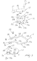
- the reference numeral 1 generally designates a lever arm, particularly for sports shoes, which can be associated with a base 2 which can be rigidly coupled to a first flap of the shoe, which is not shown in the accompanying figures.
- the base 2 has an approximately flat surface 3 and an approximately rectangular plan shape with appropriately rounded corners, from the longitudinal perimetric edges of which there protrude, approximately at right angles and preferably proximate to one of its ends, two first tabs 4a, 4b, which are mutually parallel and on which two first holes 5a, 5b are formed along a same axis.
- the lever arm 1 comprises a rigid wire-like element 6, which is preferably provided by means of a metal wire which is appropriately treated and bent until it assumes an approximately U-shaped plan configuration, in which there are two first arms, designated by the reference numerals 7a and 7b, which are bent so as to form a curl at their first ends 8a, 8b so as to form respectively two seats 9a, 9b for first means for pivoting to the pair of first tabs 4a, 4b.
- the first ends 8a, 8b of the first arms 7a, 7b have such a mutual distance as to allow their placement, during use, in the interspace and adjacent with respect to the first tabs 4a, 4b, respectively, of the base 2, preferably in engagement with their lateral surfaces, which face each other; advantageously, the first ends 8a, 8b are rotatably coupled to the contiguous first tabs 4a, 4b by means of the first pivoting means, which are constituted for example by two rivets 10a, 10b, which can be arranged in the first holes 5a, 5b and in the seats 9a, 9b.
- the two first arms 7a, 7b are connected, on the opposite side with respect to the first ends 8a, 8b, to a first base 11, which has in plan view an approximately teardrop-shaped configuration so as to form two arms, designated by the reference numerals 12a and 12b, which are mutually connected at the vertex 11a of the first base 11.
- the arms 12a, 12b are approximately V-shaped and comprise first portions 13a, 13b which are substantially straight and are connected respectively to the first arms 7a, 7b and mutually diverge away from said arms.
- the first portions 13a, 13b are connected, at the opposite end with respect to the first arms 7a, 7b, respectively to two second portions, designated by the reference numerals 14a, 14b, which are inclined by a suitable angle with respect to the first portions 13a, 13b and mutually converge toward the vertex 11a of the first base 11.
- a stiffening cage 15 is associated with the wire-like element 6 and is constituted preferably by a plate 16 which is conveniently flat and preferably made of metal or plastic material and advantageously has an approximately U-shaped plan configuration; advantageously, the cage 15 can be associated in an upper region with the wire-like element 6 by way of suitable engagement means described hereinafter.
- the plate 16 has a second base 17, which is arranged between the first portions 13a, 13b and from which two second arms 18a, 18b protrude approximately at right angles and are arranged, during use, above the first arms 7a, 7b of the wire-like element 6.
- the dimensions of the second arms 18a, 18b are such that they protrude laterally beyond the underlying first arms 7a, 7b of the wire-like element 6, so as to surround them at least partially.
- the second base 17 acts as a reinforcement to avoid possible deformations of the wire-like element 6 transversely thereto, thus increasing its solidity.
- the second free ends 19a, 19b of the second arms 18a, 18b are folded so as to partially wrap around the underlying first arms 7a, 7b of the wire-like element 6, so as to constitute said means for engaging the cage 15 with the wire-like element 6.
- the cage 15 further comprises two wings, designated respectively by the reference numerals 20a and 20b, which protrude at the connecting region between the first arms 7a, 7b and the second base 17 and are inclined with respect to the latter, so as to be superimposed during use on the first portions 13a, 13b of the first base 11 of the wire-like element 6.
- the third free ends 21a, 21b of the wings 20a, 20b are folded so as to wrap around the underlying first portions 13a, 13b of the wire-like element 6, so as to form additional means for engaging the cage 15 with the wire-like element 6.
- the cage 15 has second pivoting means for an element 22 for interconnection to appropriately provided means for engaging a second flap of said shoe, not shown in the accompanying figures.
- Such second pivoting means advantageously comprise two second tabs 23a, 23b, which protrude approximately at right angles from the non-facing longitudinal perimetric edges of the second arms 18a, 18b and in the direction of the underlying first arms 7a, 7b of the wire-like element 6 and have such dimensions as to protrude downward from them.
- the interconnection element 22 is constituted by a hollow and internally threaded cylinder 26, and is open at its end which is directed away from the second head 17 of the cage 15, in which a through opening 26a is provided transversely and within which the pivot 25 can be accommodated.
- a complementarily threaded shaft 27 is associated inside the cylinder 26 and its free end is associated rotatably with said grip means, which are constituted for example by an engagement tooth 28, which can be associated selectively with a rack 29 which in turn is associated with a second flap of the shoe, not shown in the accompanying figures.
- the lever arm according to the invention is therefore as follows.
- the cylinder 26 is arranged between the second tabs 23a and 23b of the cage 15 and is then rotatably associated with them by means of the pivot 25.
- the first ends 8a, 8b of the first arms 7a, 7b of the wire-like element 6 are then associated rotatably with the first tabs 4a, 4b of the base 2 by means of the rivets 10a, 10b, and the latter can be fixed to a first flap of a shoe, which is not shown in the accompanying figures.
- lever arm according to the invention is very strong and therefore can be used both for amateur practice and for competitive practice; in particular, a lever arm in which the cage is made of plastic material (which is cheaper but less strong than metal) can be used advantageously for amateur practice, while a metal cage can be preferred in competitive practice.
- lever arm according to the invention can be provided with production costs which are lower than those of known types of metal lever arm.
Landscapes
- Footwear And Its Accessory, Manufacturing Method And Apparatuses (AREA)
Applications Claiming Priority (1)
| Application Number | Priority Date | Filing Date | Title |
|---|---|---|---|
| ITTV20060208 ITTV20060208A1 (it) | 2006-11-16 | 2006-11-16 | Struttura di braccio leva, particolarmente per calzature sportive |
Publications (1)
| Publication Number | Publication Date |
|---|---|
| EP1922945A1 true EP1922945A1 (fr) | 2008-05-21 |
Family
ID=38828502
Family Applications (1)
| Application Number | Title | Priority Date | Filing Date |
|---|---|---|---|
| EP07117916A Withdrawn EP1922945A1 (fr) | 2006-11-16 | 2007-10-04 | Bras de levier en particulier pour chaussures de sport |
Country Status (2)
| Country | Link |
|---|---|
| EP (1) | EP1922945A1 (fr) |
| IT (1) | ITTV20060208A1 (fr) |
Cited By (6)
| Publication number | Priority date | Publication date | Assignee | Title |
|---|---|---|---|---|
| ITTV20080097A1 (it) * | 2008-07-25 | 2010-01-26 | Giorgio Baggio | Procedimento per la realizzazione di semilavorati atti a formare leve, particolarmente per calzature sportive e leve ottenute con detto procedimento. |
| ITVE20110045A1 (it) * | 2011-06-15 | 2012-12-16 | Am Teknostampi S P A | Dispositivo di chiusura a leva, in particolare per calzature sportive. |
| ITTV20130005A1 (it) * | 2013-01-17 | 2014-07-18 | Amteknostampi Spa | Struttura di dispositivo di apertura e particolarmente leve per calzature sportive |
| ITUA20164063A1 (it) * | 2016-06-01 | 2017-12-01 | Tecnica Group Spa | Dispositivo di chiusura per una calzatura sportiva |
| IT201700009944A1 (it) * | 2017-01-30 | 2018-07-30 | Tecnica Group Spa | Dispositivo di chiusura per calzatura sportiva provvisto di una leva di azionamento migliorata |
| IT201700055878A1 (it) * | 2017-05-23 | 2018-11-23 | Vega S R L | Dispositivo di chiusura |
Citations (4)
| Publication number | Priority date | Publication date | Assignee | Title |
|---|---|---|---|---|
| US1404757A (en) * | 1918-06-24 | 1922-01-31 | George N Goudy | Shoe fastener |
| US3902226A (en) * | 1973-12-03 | 1975-09-02 | Joseph F Messenbaugh | Tool for fastening a ski boot buckle |
| IT1054289B (it) * | 1976-01-21 | 1981-11-10 | Nordica S A S Di Franco | Gruppo di chiusura per scarpe da sci |
| EP0880912A2 (fr) * | 1997-05-29 | 1998-12-02 | Bauer Italia S.p.A. | Procédé de fabrication d'un dispositif de fermeture à levier et dispositif ainsi obtenu |
-
2006
- 2006-11-16 IT ITTV20060208 patent/ITTV20060208A1/it unknown
-
2007
- 2007-10-04 EP EP07117916A patent/EP1922945A1/fr not_active Withdrawn
Patent Citations (4)
| Publication number | Priority date | Publication date | Assignee | Title |
|---|---|---|---|---|
| US1404757A (en) * | 1918-06-24 | 1922-01-31 | George N Goudy | Shoe fastener |
| US3902226A (en) * | 1973-12-03 | 1975-09-02 | Joseph F Messenbaugh | Tool for fastening a ski boot buckle |
| IT1054289B (it) * | 1976-01-21 | 1981-11-10 | Nordica S A S Di Franco | Gruppo di chiusura per scarpe da sci |
| EP0880912A2 (fr) * | 1997-05-29 | 1998-12-02 | Bauer Italia S.p.A. | Procédé de fabrication d'un dispositif de fermeture à levier et dispositif ainsi obtenu |
Cited By (9)
| Publication number | Priority date | Publication date | Assignee | Title |
|---|---|---|---|---|
| ITTV20080097A1 (it) * | 2008-07-25 | 2010-01-26 | Giorgio Baggio | Procedimento per la realizzazione di semilavorati atti a formare leve, particolarmente per calzature sportive e leve ottenute con detto procedimento. |
| EP2147609A1 (fr) * | 2008-07-25 | 2010-01-27 | Premec S.P.A. | Procédé de fabrication de produits semi-finis adaptés pour former des leviers, en particulier pour chaussures de ski, et leviers obtenus par ce procédé |
| ITVE20110045A1 (it) * | 2011-06-15 | 2012-12-16 | Am Teknostampi S P A | Dispositivo di chiusura a leva, in particolare per calzature sportive. |
| ITTV20130005A1 (it) * | 2013-01-17 | 2014-07-18 | Amteknostampi Spa | Struttura di dispositivo di apertura e particolarmente leve per calzature sportive |
| ITUA20164063A1 (it) * | 2016-06-01 | 2017-12-01 | Tecnica Group Spa | Dispositivo di chiusura per una calzatura sportiva |
| EP3251537A1 (fr) * | 2016-06-01 | 2017-12-06 | Tecnica Group S.p.A. | Dispositif de fermeture pour chaussures de sport |
| IT201700009944A1 (it) * | 2017-01-30 | 2018-07-30 | Tecnica Group Spa | Dispositivo di chiusura per calzatura sportiva provvisto di una leva di azionamento migliorata |
| EP3354148A1 (fr) * | 2017-01-30 | 2018-08-01 | Tecnica Group S.p.A. | Dispositif de fermeture pour une chaussure de sport comportant un levier d'actionnement amelioré |
| IT201700055878A1 (it) * | 2017-05-23 | 2018-11-23 | Vega S R L | Dispositivo di chiusura |
Also Published As
| Publication number | Publication date |
|---|---|
| ITTV20060208A1 (it) | 2008-05-17 |
Similar Documents
| Publication | Publication Date | Title |
|---|---|---|
| EP1922945A1 (fr) | Bras de levier en particulier pour chaussures de sport | |
| WO2007011737A3 (fr) | Chaussure a lacage | |
| KR101585076B1 (ko) | 네일 교정 장치 | |
| EP0756833B1 (fr) | Dispositif de fermeture pour chaussures de sport | |
| CN107408799A (zh) | 抓线器 | |
| US20150122285A1 (en) | Eyelash curler and additional member for eyelash curler | |
| US5870826A (en) | Nail clipper gripping aid | |
| US5899483A (en) | Device for retaining a boot on a gliding board, the device including a journalled dorsal support element | |
| EP0945080A1 (fr) | Dispositif de fixation à levier pour chaussures de sport | |
| TW201139070A (en) | Pliers | |
| JPS6259595B2 (fr) | ||
| EP1774864A1 (fr) | Dispositif de fermeture à levier pour chaussures de sport | |
| EP2201855B1 (fr) | Dispositif de fermeture, en particulier pour chaussures de sport | |
| EP2165618A1 (fr) | Plaque de support pour levier, en particulier pour chaussures de sport, et procédé de fabrication | |
| EP0880912A2 (fr) | Procédé de fabrication d'un dispositif de fermeture à levier et dispositif ainsi obtenu | |
| US2712317A (en) | Eyelash curler | |
| EP1935271A1 (fr) | Levier en particulier pour chaussures de sport | |
| JP3180229U (ja) | 皮むき器 | |
| JP4904453B2 (ja) | 美容用ピンセット | |
| EP3354148B1 (fr) | Dispositif de fermeture pour une chaussure de sport comportant un levier d'actionnement amélioré | |
| KR20160064430A (ko) | 인조 속눈썹 보조장치 | |
| JP7005044B1 (ja) | ネクタイ止め | |
| KR20090102137A (ko) | 니퍼날체 및 이를 이용한 니퍼 | |
| JP4921608B1 (ja) | 爪矯正具 | |
| KR100391780B1 (ko) | 장갑 셋팅장치 |
Legal Events
| Date | Code | Title | Description |
|---|---|---|---|
| PUAI | Public reference made under article 153(3) epc to a published international application that has entered the european phase |
Free format text: ORIGINAL CODE: 0009012 |
|
| AK | Designated contracting states |
Kind code of ref document: A1 Designated state(s): AT BE BG CH CY CZ DE DK EE ES FI FR GB GR HU IE IS IT LI LT LU LV MC MT NL PL PT RO SE SI SK TR |
|
| AX | Request for extension of the european patent |
Extension state: AL BA HR MK RS |
|
| AKX | Designation fees paid | ||
| REG | Reference to a national code |
Ref country code: DE Ref legal event code: 8566 |
|
| STAA | Information on the status of an ep patent application or granted ep patent |
Free format text: STATUS: THE APPLICATION IS DEEMED TO BE WITHDRAWN |
|
| 18D | Application deemed to be withdrawn |
Effective date: 20081122 |