EP1922953A2 - Träger für einen ausziehbaren Tisch - Google Patents
Träger für einen ausziehbaren Tisch Download PDFInfo
- Publication number
- EP1922953A2 EP1922953A2 EP07120452A EP07120452A EP1922953A2 EP 1922953 A2 EP1922953 A2 EP 1922953A2 EP 07120452 A EP07120452 A EP 07120452A EP 07120452 A EP07120452 A EP 07120452A EP 1922953 A2 EP1922953 A2 EP 1922953A2
- Authority
- EP
- European Patent Office
- Prior art keywords
- tubular body
- leg part
- inner leg
- splines
- support according
- Prior art date
- Legal status (The legal status is an assumption and is not a legal conclusion. Google has not performed a legal analysis and makes no representation as to the accuracy of the status listed.)
- Granted
Links
- 229910000831 Steel Inorganic materials 0.000 claims description 4
- XAGFODPZIPBFFR-UHFFFAOYSA-N aluminium Chemical group [Al] XAGFODPZIPBFFR-UHFFFAOYSA-N 0.000 claims description 4
- 229910052782 aluminium Inorganic materials 0.000 claims description 4
- 239000004411 aluminium Substances 0.000 claims description 4
- 230000002093 peripheral effect Effects 0.000 claims description 4
- 239000010959 steel Substances 0.000 claims description 4
- 230000004308 accommodation Effects 0.000 description 2
- 238000004519 manufacturing process Methods 0.000 description 2
- 239000000654 additive Substances 0.000 description 1
- 239000000853 adhesive Substances 0.000 description 1
- 230000001070 adhesive effect Effects 0.000 description 1
- 150000001875 compounds Chemical group 0.000 description 1
- 238000010276 construction Methods 0.000 description 1
- 230000005489 elastic deformation Effects 0.000 description 1
- 238000001125 extrusion Methods 0.000 description 1
- 238000002347 injection Methods 0.000 description 1
- 239000007924 injection Substances 0.000 description 1
- 239000000463 material Substances 0.000 description 1
- 230000007246 mechanism Effects 0.000 description 1
- 238000000034 method Methods 0.000 description 1
- 239000002991 molded plastic Substances 0.000 description 1
- NJPPVKZQTLUDBO-UHFFFAOYSA-N novaluron Chemical compound C1=C(Cl)C(OC(F)(F)C(OC(F)(F)F)F)=CC=C1NC(=O)NC(=O)C1=C(F)C=CC=C1F NJPPVKZQTLUDBO-UHFFFAOYSA-N 0.000 description 1
- -1 polytetrafluorethylene Polymers 0.000 description 1
- 229920001343 polytetrafluoroethylene Polymers 0.000 description 1
- 238000005096 rolling process Methods 0.000 description 1
- 239000000126 substance Chemical group 0.000 description 1
- 238000003466 welding Methods 0.000 description 1
Images


Classifications
-
- A—HUMAN NECESSITIES
- A47—FURNITURE; DOMESTIC ARTICLES OR APPLIANCES; COFFEE MILLS; SPICE MILLS; SUCTION CLEANERS IN GENERAL
- A47B—TABLES; DESKS; OFFICE FURNITURE; CABINETS; DRAWERS; GENERAL DETAILS OF FURNITURE
- A47B13/00—Details of tables or desks
- A47B13/02—Underframes
- A47B13/023—Underframes with a central column
-
- A—HUMAN NECESSITIES
- A47—FURNITURE; DOMESTIC ARTICLES OR APPLIANCES; COFFEE MILLS; SPICE MILLS; SUCTION CLEANERS IN GENERAL
- A47B—TABLES; DESKS; OFFICE FURNITURE; CABINETS; DRAWERS; GENERAL DETAILS OF FURNITURE
- A47B9/00—Tables with tops of variable height
- A47B9/04—Tables with tops of variable height with vertical spindle
-
- A—HUMAN NECESSITIES
- A47—FURNITURE; DOMESTIC ARTICLES OR APPLIANCES; COFFEE MILLS; SPICE MILLS; SUCTION CLEANERS IN GENERAL
- A47B—TABLES; DESKS; OFFICE FURNITURE; CABINETS; DRAWERS; GENERAL DETAILS OF FURNITURE
- A47B9/00—Tables with tops of variable height
- A47B9/20—Telescopic guides
-
- A—HUMAN NECESSITIES
- A47—FURNITURE; DOMESTIC ARTICLES OR APPLIANCES; COFFEE MILLS; SPICE MILLS; SUCTION CLEANERS IN GENERAL
- A47B—TABLES; DESKS; OFFICE FURNITURE; CABINETS; DRAWERS; GENERAL DETAILS OF FURNITURE
- A47B2220/00—General furniture construction, e.g. fittings
- A47B2220/0022—Slides
- A47B2220/0025—Slides having telescoping guides with friction reducing pieces, e.g. balls between inner and outer profiles
Definitions
- Table or desk tops are often supported by one or more telescopic supports, such that the table or desk top can be raised or lowered to meet the needs of users.
- a common application is an overbed table with vertical adjustability, as found in hospitals and the like.
- this functionality is met by providing inner and outer tubes separated by, preferably, a self-lubricating bearing material such as polytetrafluorethylene. While this arrangement provides adequate utility, in order to provide a telescopic support which extends and retracts smoothly, the components need to be manufactured with relatively high precision, which entails substantial costs.
- a telescopic support forms one aspect for the invention.
- the support comprises an outer leg part and an inner leg part.
- the outer leg part has: a tubular body defining a longitudinal axis and having an interior passage through which the longitudinal axis extends centrally; and one or more longitudinally-extending splines extending radially, inwardly from the tubular body.
- the inner leg part has: a shuttle body part disposed at least in part in the tubular body; and rollers rotatably mounted to the shuttle body part to support the inner leg part for longitudinal reciprocating movement in the tubular body.
- the rollers include, for at least one of said one or more splines, at least one grooved roller having a peripheral groove which receives said spline during said reciprocating movement to constrain said outer and inner leg parts against relative rotation about the longitudinal axis.
- a height-adjustable pedestal-style table forms another aspect of the invention and comprises a foot, a telescopic support and a member.
- the foot defines a base for the table in use.
- the telescopic support comprises: an outer leg part having a tubular body secured to the foot and extending vertically therefrom in use, said tubular body defining a longitudinal axis and having an interior passage through which the longitudinal axis extends centrally; and one or more longitudinally-extending splines extending radially, inwardly from the tubular body.
- the inner leg part has: a shuttle body part disposed at least in part in the tubular body; and rollers rotatably mounted to the shuttle body part to support the inner leg part for longitudinal reciprocating movement in the tubular body.
- the rollers include, for at least one of said one or more splines, at least one grooved roller having a peripheral groove which receives said spline during said reciprocating movement to constrain said outer and inner leg parts against relative rotation about the longitudinal axis.
- the member is secured to the inner leg part and defines a work surface of the table in use.
- a telescopic support forms another aspect of the invention.
- This support comprises an outer leg part and an inner leg part.
- the outer leg part has a tubular body defining a longitudinal axis and having an interior passage through which the longitudinal axis extends centrally.
- the inner leg part has a shuttle body part and rollers.
- the shuttle body part is disposed at least in part in the tubular body.
- the rollers are rotatably mounted to the shuttle body part to support the inner leg part for longitudinal reciprocating movement in the tubular body.
- the fit between the outer leg part and the inner leg part defines a negative allowance and the tubular body deforms elastically during said reciprocating movement to accommodate such negative allowance.
- the invention permits the relatively inexpensive construction of relatively robust desks and tables that can be relatively smoothly raised and lowered.
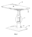
- Figure 1 is a perspective, partially cut-away view of a telescopic support constructed according to a preferred embodiment of the invention in use in a height-adjustable, pedestal-style desk which forms another preferred embodiment of the invention;
- Figure 2 is an enlarged view of encircled area 2 in Figure 1;
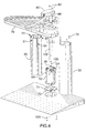
- Figure 3 is an exploded, perspective view of the desk of Figure 1, with the desk top removed, for clarity;
- Figure 4 is a view similar to Figure 3, with some parts repositioned;
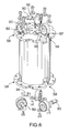
- Figure 5 is an enlarged view of encircled area 5 in Figure 3;
- Figure 6 is an exploded view of the structure of Figure 5;
- Figure 7 is a view along arrow A of Figure 4.
- Figure 8 is a cross-sectional view along axis X-X at elevation B of Figure 1.
- a height-adjustable pedestal-style table or desk constructed according to a preferred embodiment of the invention and designated with general reference numeral 20 is illustrated in partially-cut away perspective view in Figure 1 and will be seen to comprise, generally, a foot 22, a telescopic support 24 and a desk or table top member 26.
- the telescopic support 24 which will be described initially, is shown in exploded view in Figure 3 and will be seen to comprise an outer leg part 28 and an inner leg part 30.
- the outer leg part 28 has an extruded aluminium tubular body 32 which defines a longitudinal axis X-X and has an interior passage 34 through which the longitudinal axis X-X extends centrally.
- the body 32 is generally thin-shelled, but includes a plurality of longitudinally-extending stiffening ribs 36, 36', best seen in Figure 8.
- ribs 36 Six of these ribs 36 are disposed in three pairs 38, wherein the paired ribs 36 are closely-spaced to one another, the three pairs 38 being equally-spaced around the interior passage 34.
- the remaining ribs 36' are somewhat larger in cross-section than ribs 36.
- the outer leg part 28 also has at least one, specifically three, longitudinally-extending splines 40 extending radially, inwardly from the tubular body 32.
- the splines 40 are formed separately from the tubular body 32 and take the form of steel rods, each snap-fit between the ribs 36 of a respective pair 38, as shown in Figure 7, wherein the ribs 36 of each pair 38 will be seen to define a channel of semi-circular cross-section which receive in tight-fitting relation the respective spline rods 40.
- the inner leg part 30 has a shuttle body part 42, rollers 44, 46 and a fluted body part 50.
- the shuttle body part 42 is disposed at least in part in the tubular body 32 and, as best seen in Figure 5, has a substantially cylindrical centre portion 52 and notched plates 54,56 secured to the centre portion 52 and forming longitudinally-spaced upper and lower ends of the shuttle body part 42 in use.
- the rollers 44, 46 are steel, are six in number and are arranged in three pairs 48. In each pair 48, the rollers 44,46 are longitudinally-spaced from one another, each at a respective end of the shuttle body part 42 and fitted in a respective notch 58 defined in the notched plate 54,56 defining said end. The three pairs 48 are equally spaced around the shuttle body part 42.
- Each of the rollers 44, 46 is a grooved roller having a groove 60 in receipt of a respective spline 40, as shown in Figures 1 and 8, and is mounted to the shuttle body part 42 for rotation by means of an axle 90 having a ball bearing.
- Each axle 90 has an associated socket 92 in which it is received and captured by a pair of washers 94 and bolts 96, as indicated in Figures 5 and 6.
- the fluted body part 50 is an aluminium extruded member secured by bolts or screws 64 to the upper notched plate 54 of the shuttle body part 42 so as to extend longitudinally therefrom.
- the fluted body part 50 has a plurality of longitudinally-extending external grooves 51.
- the rollers 44,46 roll along the splines 40, to permit telescopic longitudinal reciprocating movement of the outer leg part 28 and the inner leg part 30.
- the engagement between the grooves 60 and splines 40 both constrains the outer 28 and inner 30 leg parts against relative rotation about the longitudinal axis X-X and provides for longitudinal alignment of the outer 28 and inner 30 leg parts, to permit constrained reciprocating relative movement parallel to the longitudinal axis X-X.
- the fit between the inner leg part 30 and outer body part 28 is of a negative allowance nature, that is, the interior dimension of the tubular body 32 and splines 40 is smaller than the exterior dimensions of the shuttle body part 42 and rollers 44,46.
- the tubular body 32 elastically deforms to receive the inner leg part 30.
- This arrangement permits smooth reciprocating motion, notwithstanding minor manufacturing imperfections that may exist.
- Further assisting this smooth reciprocating motion is a sliding fit between at least one of rollers 44 and its respective axle 90 and at least one of rollers 46 and its respective axle; such rollers 44, 46 can slide ⁇ 4 mm along their rotational axes to accommodate extrusion imperfections, etc.
- the accommodation provided by flexure of the tubular body 32 permits the various components to be manufactured relatively inexpensively, i.e. without the need for unduly high precision, with confidence that the product will still reciprocate relatively smoothly in use.
- the structure is also relatively robust.
- the foot 22 forms a base for the table 20
- the telescopic support 24, specifically, the tubular body 32 is fitted to the foot 22 to extend vertically-upwardly therefrom
- the table top member 26 is fitted to the inner leg part 28 to define a substantially horizontal, planar work surface 64, the elevation of said surface 64 being amenable to adjustment via extension or retraction of the telescopic support 24 associated with said reciprocating movement of the inner 28 and outer 30 leg parts.
- the foot 22 is a substantially wedge-shaped member which defines a socket 66 for receiving the lower end of the telescopic support 24 and has an inclined upper surface 68 that is textured for grip.
- a bottom plate 70 is secured to the lower end of the tubular body 32 by bolts 72 which engage the lower ends of spline rods 40. Bolts 72 are also fitted to the upper ends of spline rods 40, such that the spline rods 40 are locked as against longitudinal movement relative to the outer body part 32.
- a riser bracket 98 To the bottom plate 70 is secured, by bolts 74, a riser bracket 98. In turn, bracket 98 is secured by bolts 100 to a drive nut riser 102.
- Bolts 106 extend through the foot 22 and bottom plate 70 to secure tubular body 32 to foot 22.
- the table top member 26 is secured to the upper end of the fluted body 50. Such securement in the application shown is provided by an intermediate bracket 76, which is secured by bolts 78 to the upper end of the fluted body 50, and to which the table top 26 is secured by screws (not shown).
- An electrical motor 80 is secured by bolts 82 in a recess 84 of the intermediate bracket 76, and has drivably coupled thereto a threaded driveshaft 86 which, in use, extends into and is threadably received by the drive nut riser 102, such that rotation of the driveshaft 86 causes extension and retraction of the telescopic support 24, and cessation of rotation forms a mechanical lock against extension and retraction.
- rollers For example, whereas only three longitudinally-spaced pair of rollers are shown, greater numbers of longitudinally-spaced rollers could be provided. For example, four pairs of longitudinally-spaced rollers could be provided, each pair being spaced 90° from the other.
- the splines could be formed integrally, could take the form of tubes rather than rods, could have cross-sections other than round, and could be secured by welding, adhesive, rivets, screws, etc.
- outer leg part need not be extruded, nor of steel and could be formed, by way of example, by blow or rotationally-moulded plastics, or by sonically-welded injection moulded components.
- inner leg part need not be hollow, nor fluted, and mechanisms other than threaded shafts could be utilized for vertical adjustment and locking.
Landscapes
- Tables And Desks Characterized By Structural Shape (AREA)
- Workshop Equipment, Work Benches, Supports, Or Storage Means (AREA)
- Legs For Furniture In General (AREA)
- Machine Tool Units (AREA)
- Bearings For Parts Moving Linearly (AREA)
- Mutual Connection Of Rods And Tubes (AREA)
- Ladders (AREA)
- Arc Welding In General (AREA)
- Electrical Discharge Machining, Electrochemical Machining, And Combined Machining (AREA)
- Sink And Installation For Waste Water (AREA)
Applications Claiming Priority (1)
| Application Number | Priority Date | Filing Date | Title |
|---|---|---|---|
| CA2568078A CA2568078C (en) | 2006-11-14 | 2006-11-14 | Telescopic table support |
Publications (3)
| Publication Number | Publication Date |
|---|---|
| EP1922953A2 true EP1922953A2 (de) | 2008-05-21 |
| EP1922953A3 EP1922953A3 (de) | 2008-06-25 |
| EP1922953B1 EP1922953B1 (de) | 2010-06-30 |
Family
ID=38917719
Family Applications (1)
| Application Number | Title | Priority Date | Filing Date |
|---|---|---|---|
| EP07120452A Not-in-force EP1922953B1 (de) | 2006-11-14 | 2007-11-12 | Träger für einen ausziehbaren Tisch |
Country Status (6)
| Country | Link |
|---|---|
| US (1) | US8011308B2 (de) |
| EP (1) | EP1922953B1 (de) |
| AT (1) | ATE472269T1 (de) |
| CA (1) | CA2568078C (de) |
| DE (1) | DE602007007422D1 (de) |
| ES (1) | ES2348385T3 (de) |
Cited By (1)
| Publication number | Priority date | Publication date | Assignee | Title |
|---|---|---|---|---|
| ITBS20100022A1 (it) * | 2010-02-09 | 2011-08-10 | Bamelux S R L | Colonna di supporto di un piano tavolo regolabile in altezza |
Families Citing this family (90)
| Publication number | Priority date | Publication date | Assignee | Title |
|---|---|---|---|---|
| US7955357B2 (en) | 2004-07-02 | 2011-06-07 | Ellipse Technologies, Inc. | Expandable rod system to treat scoliosis and method of using the same |
| US20080087775A1 (en) * | 2006-10-11 | 2008-04-17 | Cherng Jyieh Corp. | Ascending/descending guiding structure of a support arm of a display |
| US7862502B2 (en) | 2006-10-20 | 2011-01-04 | Ellipse Technologies, Inc. | Method and apparatus for adjusting a gastrointestinal restriction device |
| US8057472B2 (en) | 2007-10-30 | 2011-11-15 | Ellipse Technologies, Inc. | Skeletal manipulation method |
| US11202707B2 (en) | 2008-03-25 | 2021-12-21 | Nuvasive Specialized Orthopedics, Inc. | Adjustable implant system |
| AU2009257352A1 (en) | 2008-06-13 | 2009-12-17 | Hill-Rom Services, Inc. | Item support apparatuses and systems for bedside |
| EP2160958B1 (de) * | 2008-09-08 | 2016-06-29 | Linak A/S | Höhenverstellbarer Tisch |
| US11241257B2 (en) | 2008-10-13 | 2022-02-08 | Nuvasive Specialized Orthopedics, Inc. | Spinal distraction system |
| US8382756B2 (en) | 2008-11-10 | 2013-02-26 | Ellipse Technologies, Inc. | External adjustment device for distraction device |
| US8197490B2 (en) | 2009-02-23 | 2012-06-12 | Ellipse Technologies, Inc. | Non-invasive adjustable distraction system |
| US9622792B2 (en) | 2009-04-29 | 2017-04-18 | Nuvasive Specialized Orthopedics, Inc. | Interspinous process device and method |
| US20110010854A1 (en) | 2009-07-15 | 2011-01-20 | Zerhusen Robert M | Siderail with storage area |
| KR101710741B1 (ko) * | 2009-09-04 | 2017-02-27 | 누베이시브 스페셜라이즈드 오소페딕스, 인크. | 뼈 성장 기구 및 방법 |
| IT1397416B1 (it) * | 2010-01-12 | 2013-01-10 | Barracchia | Tavolo con base telescopica-basculante. |
| US9248043B2 (en) | 2010-06-30 | 2016-02-02 | Ellipse Technologies, Inc. | External adjustment device for distraction device |
| EP2597992B1 (de) * | 2010-07-29 | 2015-10-07 | Linak A/S | Hebesäule, vorzugsweise für höhenverstellbare tische |
| US8734488B2 (en) | 2010-08-09 | 2014-05-27 | Ellipse Technologies, Inc. | Maintenance feature in magnetic implant |
| US8522511B2 (en) * | 2010-12-20 | 2013-09-03 | Raytheon Company | Methods and apparatus for mast system with enhanced load bearing |
| CN102039650A (zh) * | 2010-12-24 | 2011-05-04 | 上海雷博司电器有限公司 | 内套支撑装置 |
| US8852187B2 (en) | 2011-02-14 | 2014-10-07 | Ellipse Technologies, Inc. | Variable length device and method |
| USD655109S1 (en) * | 2011-05-13 | 2012-03-06 | Steelcase Inc. | Table |
| US10743794B2 (en) | 2011-10-04 | 2020-08-18 | Nuvasive Specialized Orthopedics, Inc. | Devices and methods for non-invasive implant length sensing |
| WO2013066946A1 (en) | 2011-11-01 | 2013-05-10 | Ellipse Technologies, Inc. | Adjustable magnetic devices and methods of using same |
| US20130141902A1 (en) * | 2011-12-01 | 2013-06-06 | Sol Inc. | Pole support system |
| US20130338714A1 (en) | 2012-06-15 | 2013-12-19 | Arvin Chang | Magnetic implants with improved anatomical compatibility |
| USD692702S1 (en) * | 2012-07-18 | 2013-11-05 | Stander Inc. | Bedrail and tray |
| US9089217B2 (en) | 2012-09-21 | 2015-07-28 | Baultar I.D. Inc. | Seat adjustment system |
| US9044281B2 (en) | 2012-10-18 | 2015-06-02 | Ellipse Technologies, Inc. | Intramedullary implants for replacing lost bone |
| EP3760147B1 (de) | 2012-10-29 | 2022-11-30 | NuVasive Specialized Orthopedics, Inc. | Einstellbare vorrichtungen zur behandlung von arthritis des kniegelenks |
| US9179938B2 (en) | 2013-03-08 | 2015-11-10 | Ellipse Technologies, Inc. | Distraction devices and method of assembling the same |
| US9271569B2 (en) | 2013-03-11 | 2016-03-01 | Herman Miller, Inc. | Reconfigurable table |
| USD743189S1 (en) | 2013-03-15 | 2015-11-17 | Herman Miller, Inc. | Workstation |
| US10226242B2 (en) | 2013-07-31 | 2019-03-12 | Nuvasive Specialized Orthopedics, Inc. | Noninvasively adjustable suture anchors |
| US9801734B1 (en) | 2013-08-09 | 2017-10-31 | Nuvasive, Inc. | Lordotic expandable interbody implant |
| USD719382S1 (en) * | 2013-09-18 | 2014-12-16 | Wire Fab Company | Shoe display stand |
| USD718960S1 (en) * | 2013-09-18 | 2014-12-09 | Wire Fab Company | Shoe display stand |
| USD718959S1 (en) * | 2013-09-18 | 2014-12-09 | Wire Fab Company | Shoe display stand |
| US10751094B2 (en) | 2013-10-10 | 2020-08-25 | Nuvasive Specialized Orthopedics, Inc. | Adjustable spinal implant |
| AU2015253313B9 (en) | 2014-04-28 | 2020-09-10 | Nuvasive Specialized Orthopedics, Inc. | System for informational magnetic feedback in adjustable implants |
| US9371663B2 (en) * | 2014-05-07 | 2016-06-21 | Us Tower Corporation | Internally keyed extruded mast system |
| CN104075090B (zh) * | 2014-06-16 | 2016-08-24 | 苏州市电子产品检验所有限公司 | Led显示屏检测支架 |
| TWM496965U (zh) * | 2014-10-09 | 2015-03-11 | Chun-Tsair Wang | 伸縮支撐裝置及伸縮支撐柱 |
| USD799864S1 (en) | 2014-10-13 | 2017-10-17 | Sheri Bauer | Table |
| WO2016065205A1 (en) | 2014-10-23 | 2016-04-28 | Ellipse Technologies, Inc. | Remotely adjustable interactive bone reshaping implant |
| EP3236867B1 (de) | 2014-12-26 | 2022-02-23 | NuVasive Specialized Orthopedics, Inc. | Distraktionssysteme |
| US9380866B1 (en) | 2015-02-11 | 2016-07-05 | Bradford L. Davis | Telescopic support |
| US10238427B2 (en) | 2015-02-19 | 2019-03-26 | Nuvasive Specialized Orthopedics, Inc. | Systems and methods for vertebral adjustment |
| USD774322S1 (en) * | 2015-10-01 | 2016-12-20 | GCX Corporation | Over bed table |
| US9788647B2 (en) | 2015-10-13 | 2017-10-17 | Nishan Joshi | Overbed table |
| EP3361960B1 (de) | 2015-10-16 | 2023-05-10 | NuVasive Specialized Orthopedics, Inc. | Einstellbare vorrichtungen zur behandlung von arthritis des kniegelenks |
| CN108601611B (zh) | 2015-12-10 | 2021-11-02 | 诺威适骨科专科公司 | 用于牵张装置的外部调节装置 |
| CN108882953B (zh) | 2016-01-28 | 2021-09-03 | 诺威适骨科专科公司 | 骨搬移用的系统 |
| WO2017139548A1 (en) | 2016-02-10 | 2017-08-17 | Nuvasive Specialized Orthopedics, Inc. | Systems and methods for controlling multiple surgical variables |
| USD805799S1 (en) * | 2016-08-29 | 2017-12-26 | Tri-Nix Llc | Bedside table |
| US9854913B1 (en) * | 2017-05-11 | 2018-01-02 | Ann Yang Inc. | Telescopic leg unit for table and chair |
| TWM550795U (zh) * | 2017-07-12 | 2017-10-21 | Jarllytec Co Ltd | 用於升降裝置的滑移機構 |
| CA3017867C (en) * | 2017-09-18 | 2021-04-27 | Coast Dynamics Group Ltd. | Suspension pedestal |
| EP3706598B1 (de) * | 2017-11-09 | 2022-01-05 | Oelschläger Metalltechnik GmbH | Teleskopierbare säule, insbesondere für möbel, wie tische, und tisch mit einer derartigen säule |
| CN107928108A (zh) * | 2017-12-25 | 2018-04-20 | 江阴市高奕机械工业有限公司 | 桌子升降装置 |
| CN107928105A (zh) * | 2017-12-25 | 2018-04-20 | 江阴市高奕机械工业有限公司 | 单柱升降桌 |
| CN108937140A (zh) * | 2018-07-24 | 2018-12-07 | 合肥爱玩动漫有限公司 | 一种方便调节高度的动漫设计用画板支架 |
| US20200254283A1 (en) | 2019-02-07 | 2020-08-13 | Nuvasive Specialized Orthopedics, Inc. | Medical devices for ultrasonic therapy |
| US11589901B2 (en) | 2019-02-08 | 2023-02-28 | Nuvasive Specialized Orthopedics, Inc. | External adjustment device |
| US11371644B2 (en) * | 2019-05-31 | 2022-06-28 | Apple Inc. | Dual display stand |
| EP4025140B1 (de) | 2019-09-03 | 2025-07-09 | NuVasive Specialized Orthopedics, Inc. | Akustische meldung für dynamische implantate |
| US12108872B2 (en) | 2019-09-06 | 2024-10-08 | Itc Incorporated | Pedestal leg assembly |
| US11304509B2 (en) * | 2019-09-06 | 2022-04-19 | Itc Incorporated | Pedestal leg assembly |
| US11459787B2 (en) * | 2020-02-21 | 2022-10-04 | Kane Innovations, Inc. | Reinforced mechanical post |
| US12605192B2 (en) | 2020-07-15 | 2026-04-21 | Globus Medical, Inc. | Ultrasonic communication in adjustable implants |
| US12213708B2 (en) | 2020-09-08 | 2025-02-04 | Nuvasive Specialized Orthopedics, Inc. | Remote control module for adjustable implants |
| USD953341S1 (en) * | 2020-09-30 | 2022-05-31 | Shenzhen Boyata Electronic Co., Ltd. | Monitor stand |
| CN115803534A (zh) * | 2020-11-25 | 2023-03-14 | 张小川 | 一种任意停阻力伸缩杆及其设备装置以及使用方法 |
| EP4297674A1 (de) | 2021-02-23 | 2024-01-03 | NuVasive Specialized Orthopedics, Inc. | Einstellbares implantat, system und verfahren |
| JP7593223B2 (ja) | 2021-05-10 | 2024-12-03 | コクヨ株式会社 | 天板付き家具 |
| US11737787B1 (en) | 2021-05-27 | 2023-08-29 | Nuvasive, Inc. | Bone elongating devices and methods of use |
| US12023073B2 (en) | 2021-08-03 | 2024-07-02 | Nuvasive Specialized Orthopedics, Inc. | Adjustable implant |
| CN215936801U (zh) * | 2021-08-16 | 2022-03-04 | 邵武市枫桦机电设计有限公司 | 一种可调的支撑装配构件 |
| USD965601S1 (en) * | 2021-09-22 | 2022-10-04 | Shenzhen Bestqi Innovation Technology Co., Ltd | Laptop stand |
| CN114190692B (zh) * | 2021-10-09 | 2023-01-20 | 青岛问峰实业有限公司 | 升降桌 |
| USD991938S1 (en) * | 2021-11-18 | 2023-07-11 | ACCO Brands Corporation | Electronic device stand |
| CN114321176B (zh) * | 2021-12-31 | 2024-02-20 | 常州市双爱家私股份有限公司 | 一种升降桌椅用内置滑动装置 |
| USD1025082S1 (en) * | 2022-04-08 | 2024-04-30 | Shenzhen Jianyi Technology Co., Ltd. | Laptop stand |
| US12551240B2 (en) | 2022-06-13 | 2026-02-17 | Nuvasive Inc. | Distraction loss magnet on-off mechanism |
| US12458417B2 (en) | 2022-08-15 | 2025-11-04 | Nuvasive Specialized Orthopedics Inc. | Intermedullary lengthening implant with integrated load sensor |
| CN115316783B (zh) * | 2022-08-27 | 2024-04-19 | 乐歌人体工学科技股份有限公司 | 带健身杆的电动升降桌 |
| US12508058B2 (en) | 2022-10-07 | 2025-12-30 | Nuvasive Specialized Orthopedics, Inc. | Adjustable tether implant |
| US11920728B1 (en) | 2022-12-22 | 2024-03-05 | MillerKnoll, Inc. | Accessory mounting system |
| US12558133B2 (en) | 2023-04-25 | 2026-02-24 | Nuvasive, Inc. | Flat plate mechanisms for bone lengthening |
| US12533164B2 (en) | 2023-05-03 | 2026-01-27 | Nuvasive Specialized Orthopedics, Inc. | Adjustable implant |
| USD1093006S1 (en) | 2024-03-15 | 2025-09-16 | Stander, Inc. | Furniture tray table |
Citations (2)
| Publication number | Priority date | Publication date | Assignee | Title |
|---|---|---|---|---|
| US4381095A (en) | 1980-10-14 | 1983-04-26 | Mayline Co., Inc. | Apparatus for supporting a work surface |
| EP1270972A1 (de) | 2001-06-21 | 2003-01-02 | Steelcase Sa | Teleskopische Führungseinrichtung eines inneren Rohres in einer äusseren rohrförmigen Umhüllung |
Family Cites Families (17)
| Publication number | Priority date | Publication date | Assignee | Title |
|---|---|---|---|---|
| US1919114A (en) * | 1931-07-07 | 1933-07-18 | Ley George Albert | Lamp stand |
| US2684159A (en) * | 1950-07-12 | 1954-07-20 | Warner Swasey Co | Telescoping boom actuating mechanism |
| FR1531447A (fr) * | 1967-04-11 | 1968-07-05 | Table à dessiner | |
| US3521341A (en) * | 1968-06-17 | 1970-07-21 | Reinhard Hornlein Kg | Method of assembling and forming an extensible column |
| US3776500A (en) * | 1971-07-16 | 1973-12-04 | Picker Corp | X-ray apparatus having a telescopic columnar support |
| CH589437A5 (de) * | 1975-09-30 | 1977-07-15 | Contraves Ag | |
| DE3635700A1 (de) * | 1986-10-21 | 1988-04-28 | Michael Schmeller | Hubeinrichtung |
| US5249881A (en) * | 1992-03-20 | 1993-10-05 | A-Dec, Inc. | Telescoping arm apparatus |
| US5339750A (en) * | 1992-03-27 | 1994-08-23 | Hamilton Industries | Adjustable work table |
| US5385323A (en) * | 1993-10-14 | 1995-01-31 | Garelick; Richard J. | Telescoped tubular support members |
| US5845590A (en) * | 1995-01-31 | 1998-12-08 | Krueger International, Inc. | Adjustable height table |
| US6378816B1 (en) * | 1999-06-04 | 2002-04-30 | Joel W. Pfister | Linear motion table leg |
| DE10054236A1 (de) * | 2000-11-02 | 2002-07-25 | Okin Ges Fuer Antriebstechnik | Teleskoparm |
| US6443406B1 (en) * | 2001-02-16 | 2002-09-03 | Kompan A/S | Means of mounting and adjusting telescopic metal tubes |
| DE20214378U1 (de) * | 2002-09-16 | 2004-02-26 | Herbert Grüttner GmbH & Co. KG | Teleskopsäule (III) |
| SE524071C2 (sv) * | 2002-11-08 | 2004-06-22 | Rol Ergonomic Ab | Anordning för kontrollerad teleskopering av flerstegs teleskoprör samt sätt att medelst en dylik anordning synkronisera samverkande teleskoprörsektioner med avseende på deras rörelseförlopp |
| WO2006066116A2 (en) * | 2004-12-17 | 2006-06-22 | Steelcase Development Corporation | Height adjustable table |
-
2006
- 2006-11-14 CA CA2568078A patent/CA2568078C/en not_active Expired - Fee Related
-
2007
- 2007-11-12 EP EP07120452A patent/EP1922953B1/de not_active Not-in-force
- 2007-11-12 ES ES07120452T patent/ES2348385T3/es active Active
- 2007-11-12 AT AT07120452T patent/ATE472269T1/de not_active IP Right Cessation
- 2007-11-12 DE DE602007007422T patent/DE602007007422D1/de active Active
- 2007-11-13 US US11/938,924 patent/US8011308B2/en active Active
Patent Citations (2)
| Publication number | Priority date | Publication date | Assignee | Title |
|---|---|---|---|---|
| US4381095A (en) | 1980-10-14 | 1983-04-26 | Mayline Co., Inc. | Apparatus for supporting a work surface |
| EP1270972A1 (de) | 2001-06-21 | 2003-01-02 | Steelcase Sa | Teleskopische Führungseinrichtung eines inneren Rohres in einer äusseren rohrförmigen Umhüllung |
Cited By (1)
| Publication number | Priority date | Publication date | Assignee | Title |
|---|---|---|---|---|
| ITBS20100022A1 (it) * | 2010-02-09 | 2011-08-10 | Bamelux S R L | Colonna di supporto di un piano tavolo regolabile in altezza |
Also Published As
| Publication number | Publication date |
|---|---|
| CA2568078C (en) | 2014-03-18 |
| ES2348385T3 (es) | 2010-12-03 |
| ATE472269T1 (de) | 2010-07-15 |
| US8011308B2 (en) | 2011-09-06 |
| CA2568078A1 (en) | 2008-05-14 |
| EP1922953B1 (de) | 2010-06-30 |
| DE602007007422D1 (de) | 2010-08-12 |
| EP1922953A3 (de) | 2008-06-25 |
| US20080121150A1 (en) | 2008-05-29 |
Similar Documents
| Publication | Publication Date | Title |
|---|---|---|
| EP1922953B1 (de) | Träger für einen ausziehbaren Tisch | |
| US9247806B2 (en) | Lifting column preferably for height-adjustable tables | |
| US7163498B1 (en) | Cantilevering linear motion exercise device and method of physical exercise | |
| US20040211275A1 (en) | Telescopically moving structure | |
| US20190174913A1 (en) | Device for table elevation | |
| AU2001260086A1 (en) | Telescopically moving structure | |
| US9005086B1 (en) | Portable rowing machine | |
| CN208166526U (zh) | 调整机构,及具有该调整机构的升降装置 | |
| US9833377B2 (en) | Walker | |
| CN212282678U (zh) | 一种哑铃及其手柄和底座 | |
| CN115038364B (zh) | 具有可逆腿组合件的桌组合件 | |
| CA3162086C (en) | LOCKING DEVICE FOR A TELESCOPIC LEG | |
| CN111315258A (zh) | 具体用于家具例如桌子的可伸缩柱以及具有该柱的桌子 | |
| CN210943416U (zh) | 可调高度的输送滚筒 | |
| US20140087929A1 (en) | Motion muscle relaxer | |
| CN101554268B (zh) | 伸缩式工作台支架 | |
| CN1250135C (zh) | 支承表面的高度可调节腿 | |
| CN215351762U (zh) | 一种伸缩支承机构和包含该机构的跳马 | |
| SE544482C2 (en) | Adjustable telescopic leg with locking mechanism comprising a resilitently loaded fixating member | |
| CN213308120U (zh) | 一种设有稳定连接结构的桌子 | |
| EP1080665A1 (de) | Regelbarer, teleskopischer Aufbau | |
| CN110005923B (zh) | 升降可调式电脑显示器柱座部件 | |
| US20060118682A1 (en) | Furniture leg assembly | |
| CN223399039U (zh) | 一种单手操作伸缩杆 | |
| CN218853381U (zh) | 一种伸缩式单杠 |
Legal Events
| Date | Code | Title | Description |
|---|---|---|---|
| PUAI | Public reference made under article 153(3) epc to a published international application that has entered the european phase |
Free format text: ORIGINAL CODE: 0009012 |
|
| AK | Designated contracting states |
Kind code of ref document: A2 Designated state(s): AT BE BG CH CY CZ DE DK EE ES FI FR GB GR HU IE IS IT LI LT LU LV MC MT NL PL PT RO SE SI SK TR |
|
| AX | Request for extension of the european patent |
Extension state: AL BA HR MK RS |
|
| PUAL | Search report despatched |
Free format text: ORIGINAL CODE: 0009013 |
|
| AK | Designated contracting states |
Kind code of ref document: A3 Designated state(s): AT BE BG CH CY CZ DE DK EE ES FI FR GB GR HU IE IS IT LI LT LU LV MC MT NL PL PT RO SE SI SK TR |
|
| AX | Request for extension of the european patent |
Extension state: AL BA HR MK RS |
|
| 17P | Request for examination filed |
Effective date: 20081218 |
|
| AKX | Designation fees paid |
Designated state(s): AT BE BG CH CY CZ DE DK EE ES FI FR GB GR HU IE IS IT LI LT LU LV MC MT NL PL PT RO SE SI SK TR |
|
| 17Q | First examination report despatched |
Effective date: 20090205 |
|
| GRAP | Despatch of communication of intention to grant a patent |
Free format text: ORIGINAL CODE: EPIDOSNIGR1 |
|
| GRAS | Grant fee paid |
Free format text: ORIGINAL CODE: EPIDOSNIGR3 |
|
| GRAA | (expected) grant |
Free format text: ORIGINAL CODE: 0009210 |
|
| AK | Designated contracting states |
Kind code of ref document: B1 Designated state(s): AT BE BG CH CY CZ DE DK EE ES FI FR GB GR HU IE IS IT LI LT LU LV MC MT NL PL PT RO SE SI SK TR |
|
| REG | Reference to a national code |
Ref country code: CH Ref legal event code: EP Ref country code: GB Ref legal event code: FG4D |
|
| REG | Reference to a national code |
Ref country code: IE Ref legal event code: FG4D |
|
| REF | Corresponds to: |
Ref document number: 602007007422 Country of ref document: DE Date of ref document: 20100812 Kind code of ref document: P |
|
| REG | Reference to a national code |
Ref country code: NL Ref legal event code: VDEP Effective date: 20100630 |
|
| PG25 | Lapsed in a contracting state [announced via postgrant information from national office to epo] |
Ref country code: LT Free format text: LAPSE BECAUSE OF FAILURE TO SUBMIT A TRANSLATION OF THE DESCRIPTION OR TO PAY THE FEE WITHIN THE PRESCRIBED TIME-LIMIT Effective date: 20100630 Ref country code: SE Free format text: LAPSE BECAUSE OF FAILURE TO SUBMIT A TRANSLATION OF THE DESCRIPTION OR TO PAY THE FEE WITHIN THE PRESCRIBED TIME-LIMIT Effective date: 20100630 |
|
| REG | Reference to a national code |
Ref country code: ES Ref legal event code: FG2A Effective date: 20101123 |
|
| LTIE | Lt: invalidation of european patent or patent extension |
Effective date: 20100630 |
|
| PG25 | Lapsed in a contracting state [announced via postgrant information from national office to epo] |
Ref country code: FI Free format text: LAPSE BECAUSE OF FAILURE TO SUBMIT A TRANSLATION OF THE DESCRIPTION OR TO PAY THE FEE WITHIN THE PRESCRIBED TIME-LIMIT Effective date: 20100630 Ref country code: SI Free format text: LAPSE BECAUSE OF FAILURE TO SUBMIT A TRANSLATION OF THE DESCRIPTION OR TO PAY THE FEE WITHIN THE PRESCRIBED TIME-LIMIT Effective date: 20100630 Ref country code: AT Free format text: LAPSE BECAUSE OF FAILURE TO SUBMIT A TRANSLATION OF THE DESCRIPTION OR TO PAY THE FEE WITHIN THE PRESCRIBED TIME-LIMIT Effective date: 20100630 Ref country code: LV Free format text: LAPSE BECAUSE OF FAILURE TO SUBMIT A TRANSLATION OF THE DESCRIPTION OR TO PAY THE FEE WITHIN THE PRESCRIBED TIME-LIMIT Effective date: 20100630 |
|
| PG25 | Lapsed in a contracting state [announced via postgrant information from national office to epo] |
Ref country code: PL Free format text: LAPSE BECAUSE OF FAILURE TO SUBMIT A TRANSLATION OF THE DESCRIPTION OR TO PAY THE FEE WITHIN THE PRESCRIBED TIME-LIMIT Effective date: 20100630 |
|
| PG25 | Lapsed in a contracting state [announced via postgrant information from national office to epo] |
Ref country code: NL Free format text: LAPSE BECAUSE OF FAILURE TO SUBMIT A TRANSLATION OF THE DESCRIPTION OR TO PAY THE FEE WITHIN THE PRESCRIBED TIME-LIMIT Effective date: 20100630 Ref country code: EE Free format text: LAPSE BECAUSE OF FAILURE TO SUBMIT A TRANSLATION OF THE DESCRIPTION OR TO PAY THE FEE WITHIN THE PRESCRIBED TIME-LIMIT Effective date: 20100630 |
|
| PG25 | Lapsed in a contracting state [announced via postgrant information from national office to epo] |
Ref country code: BE Free format text: LAPSE BECAUSE OF FAILURE TO SUBMIT A TRANSLATION OF THE DESCRIPTION OR TO PAY THE FEE WITHIN THE PRESCRIBED TIME-LIMIT Effective date: 20100630 Ref country code: IS Free format text: LAPSE BECAUSE OF FAILURE TO SUBMIT A TRANSLATION OF THE DESCRIPTION OR TO PAY THE FEE WITHIN THE PRESCRIBED TIME-LIMIT Effective date: 20101030 Ref country code: CZ Free format text: LAPSE BECAUSE OF FAILURE TO SUBMIT A TRANSLATION OF THE DESCRIPTION OR TO PAY THE FEE WITHIN THE PRESCRIBED TIME-LIMIT Effective date: 20100630 Ref country code: RO Free format text: LAPSE BECAUSE OF FAILURE TO SUBMIT A TRANSLATION OF THE DESCRIPTION OR TO PAY THE FEE WITHIN THE PRESCRIBED TIME-LIMIT Effective date: 20100630 Ref country code: CY Free format text: LAPSE BECAUSE OF FAILURE TO SUBMIT A TRANSLATION OF THE DESCRIPTION OR TO PAY THE FEE WITHIN THE PRESCRIBED TIME-LIMIT Effective date: 20100630 Ref country code: PT Free format text: LAPSE BECAUSE OF FAILURE TO SUBMIT A TRANSLATION OF THE DESCRIPTION OR TO PAY THE FEE WITHIN THE PRESCRIBED TIME-LIMIT Effective date: 20101102 Ref country code: SK Free format text: LAPSE BECAUSE OF FAILURE TO SUBMIT A TRANSLATION OF THE DESCRIPTION OR TO PAY THE FEE WITHIN THE PRESCRIBED TIME-LIMIT Effective date: 20100630 |
|
| PG25 | Lapsed in a contracting state [announced via postgrant information from national office to epo] |
Ref country code: DK Free format text: LAPSE BECAUSE OF FAILURE TO SUBMIT A TRANSLATION OF THE DESCRIPTION OR TO PAY THE FEE WITHIN THE PRESCRIBED TIME-LIMIT Effective date: 20100630 Ref country code: GR Free format text: LAPSE BECAUSE OF FAILURE TO SUBMIT A TRANSLATION OF THE DESCRIPTION OR TO PAY THE FEE WITHIN THE PRESCRIBED TIME-LIMIT Effective date: 20101001 |
|
| PLBE | No opposition filed within time limit |
Free format text: ORIGINAL CODE: 0009261 |
|
| STAA | Information on the status of an ep patent application or granted ep patent |
Free format text: STATUS: NO OPPOSITION FILED WITHIN TIME LIMIT |
|
| 26N | No opposition filed |
Effective date: 20110331 |
|
| PG25 | Lapsed in a contracting state [announced via postgrant information from national office to epo] |
Ref country code: MC Free format text: LAPSE BECAUSE OF NON-PAYMENT OF DUE FEES Effective date: 20101130 |
|
| REG | Reference to a national code |
Ref country code: DE Ref legal event code: R097 Ref document number: 602007007422 Country of ref document: DE Effective date: 20110330 |
|
| PG25 | Lapsed in a contracting state [announced via postgrant information from national office to epo] |
Ref country code: IE Free format text: LAPSE BECAUSE OF NON-PAYMENT OF DUE FEES Effective date: 20101112 |
|
| PG25 | Lapsed in a contracting state [announced via postgrant information from national office to epo] |
Ref country code: IT Free format text: LAPSE BECAUSE OF NON-PAYMENT OF DUE FEES Effective date: 20101112 Ref country code: MT Free format text: LAPSE BECAUSE OF FAILURE TO SUBMIT A TRANSLATION OF THE DESCRIPTION OR TO PAY THE FEE WITHIN THE PRESCRIBED TIME-LIMIT Effective date: 20100630 |
|
| REG | Reference to a national code |
Ref country code: CH Ref legal event code: PL |
|
| GBPC | Gb: european patent ceased through non-payment of renewal fee |
Effective date: 20111112 |
|
| PG25 | Lapsed in a contracting state [announced via postgrant information from national office to epo] |
Ref country code: CH Free format text: LAPSE BECAUSE OF NON-PAYMENT OF DUE FEES Effective date: 20111130 Ref country code: LI Free format text: LAPSE BECAUSE OF NON-PAYMENT OF DUE FEES Effective date: 20111130 |
|
| PG25 | Lapsed in a contracting state [announced via postgrant information from national office to epo] |
Ref country code: BG Free format text: LAPSE BECAUSE OF FAILURE TO SUBMIT A TRANSLATION OF THE DESCRIPTION OR TO PAY THE FEE WITHIN THE PRESCRIBED TIME-LIMIT Effective date: 20100630 Ref country code: HU Free format text: LAPSE BECAUSE OF FAILURE TO SUBMIT A TRANSLATION OF THE DESCRIPTION OR TO PAY THE FEE WITHIN THE PRESCRIBED TIME-LIMIT Effective date: 20110101 Ref country code: LU Free format text: LAPSE BECAUSE OF NON-PAYMENT OF DUE FEES Effective date: 20101112 |
|
| PG25 | Lapsed in a contracting state [announced via postgrant information from national office to epo] |
Ref country code: GB Free format text: LAPSE BECAUSE OF NON-PAYMENT OF DUE FEES Effective date: 20111112 Ref country code: TR Free format text: LAPSE BECAUSE OF FAILURE TO SUBMIT A TRANSLATION OF THE DESCRIPTION OR TO PAY THE FEE WITHIN THE PRESCRIBED TIME-LIMIT Effective date: 20100630 |
|
| PG25 | Lapsed in a contracting state [announced via postgrant information from national office to epo] |
Ref country code: BG Free format text: LAPSE BECAUSE OF FAILURE TO SUBMIT A TRANSLATION OF THE DESCRIPTION OR TO PAY THE FEE WITHIN THE PRESCRIBED TIME-LIMIT Effective date: 20100930 |
|
| REG | Reference to a national code |
Ref country code: FR Ref legal event code: PLFP Year of fee payment: 9 |
|
| REG | Reference to a national code |
Ref country code: FR Ref legal event code: PLFP Year of fee payment: 10 |
|
| REG | Reference to a national code |
Ref country code: FR Ref legal event code: PLFP Year of fee payment: 11 |
|
| PGFP | Annual fee paid to national office [announced via postgrant information from national office to epo] |
Ref country code: DE Payment date: 20191129 Year of fee payment: 13 |
|
| PGFP | Annual fee paid to national office [announced via postgrant information from national office to epo] |
Ref country code: IT Payment date: 20191107 Year of fee payment: 13 Ref country code: FR Payment date: 20191129 Year of fee payment: 13 |
|
| PGFP | Annual fee paid to national office [announced via postgrant information from national office to epo] |
Ref country code: ES Payment date: 20200227 Year of fee payment: 13 |
|
| REG | Reference to a national code |
Ref country code: DE Ref legal event code: R119 Ref document number: 602007007422 Country of ref document: DE |
|
| PG25 | Lapsed in a contracting state [announced via postgrant information from national office to epo] |
Ref country code: FR Free format text: LAPSE BECAUSE OF NON-PAYMENT OF DUE FEES Effective date: 20201130 Ref country code: IT Free format text: LAPSE BECAUSE OF NON-PAYMENT OF DUE FEES Effective date: 20201112 |
|
| PG25 | Lapsed in a contracting state [announced via postgrant information from national office to epo] |
Ref country code: DE Free format text: LAPSE BECAUSE OF NON-PAYMENT OF DUE FEES Effective date: 20210601 |
|
| REG | Reference to a national code |
Ref country code: ES Ref legal event code: FD2A Effective date: 20220201 |
|
| PG25 | Lapsed in a contracting state [announced via postgrant information from national office to epo] |
Ref country code: ES Free format text: LAPSE BECAUSE OF NON-PAYMENT OF DUE FEES Effective date: 20201113 |