EP1922970A2 - Staubsauger mit Plattenfilter - Google Patents
Staubsauger mit Plattenfilter Download PDFInfo
- Publication number
- EP1922970A2 EP1922970A2 EP07121077A EP07121077A EP1922970A2 EP 1922970 A2 EP1922970 A2 EP 1922970A2 EP 07121077 A EP07121077 A EP 07121077A EP 07121077 A EP07121077 A EP 07121077A EP 1922970 A2 EP1922970 A2 EP 1922970A2
- Authority
- EP
- European Patent Office
- Prior art keywords
- vacuum
- filter
- inlet opening
- housing
- suction inlet
- Prior art date
- Legal status (The legal status is an assumption and is not a legal conclusion. Google has not performed a legal analysis and makes no representation as to the accuracy of the status listed.)
- Granted
Links
- 238000004891 communication Methods 0.000 claims description 6
- 238000003780 insertion Methods 0.000 claims description 5
- 230000037431 insertion Effects 0.000 claims description 5
- 239000000463 material Substances 0.000 description 8
- 238000004140 cleaning Methods 0.000 description 3
- 238000010276 construction Methods 0.000 description 2
- 239000012530 fluid Substances 0.000 description 2
- 230000008878 coupling Effects 0.000 description 1
- 238000010168 coupling process Methods 0.000 description 1
- 238000005859 coupling reaction Methods 0.000 description 1
- 239000013536 elastomeric material Substances 0.000 description 1
- 230000009467 reduction Effects 0.000 description 1
- 238000007789 sealing Methods 0.000 description 1
Images


Classifications
-
- A—HUMAN NECESSITIES
- A47—FURNITURE; DOMESTIC ARTICLES OR APPLIANCES; COFFEE MILLS; SPICE MILLS; SUCTION CLEANERS IN GENERAL
- A47L—DOMESTIC WASHING OR CLEANING; SUCTION CLEANERS IN GENERAL
- A47L9/00—Details or accessories of suction cleaners, e.g. mechanical means for controlling the suction or for effecting pulsating action; Storing devices specially adapted to suction cleaners or parts thereof; Carrying-vehicles specially adapted for suction cleaners
- A47L9/10—Filters; Dust separators; Dust removal; Automatic exchange of filters
- A47L9/12—Dry filters
- A47L9/122—Dry filters flat
Definitions
- the present disclosure relates to vacuum filters, and more particularly, to a vacuum having a panel filter that is removable externally of the vacuum to allow easy cleaning and replacement of the filter panel without disassembly of the vacuum.
- Vacuums particularly industrial shop vacuums may be equipped with a filter unit which is attached directly to an inlet passage of the vacuum head that is connected to the vacuum source.
- the vacuum head In order to access this vacuum filter, the vacuum head must be removed from the canister. Then, the vacuum filter must be either removed, or cleaned while mounted securely to the vacuum head. Cleaning and/or removing the filter can be cumbersome and messy.
- the present disclosure provides a vacuum including a housing defining a suction inlet opening and a debris chamber in communication with the suction inlet opening.
- a vacuum pressure source is disposed in the housing for providing a vacuum pressure to the suction inlet opening.
- a removable filter tray is accessible from the exterior of the housing and is disposed in an airflow path between the suction inlet opening and the vacuum pressure source.
- the removable filter tray can be inserted at an angle between 10 and 30 degrees relative to horizontal so that the filter tray can extend partially into the housing canister.
- the vacuum pressure source can include an electric motor operable to drive an impeller.
- the electric motor and the impeller can be disposed in the housing for providing a vacuum pressure to the suction inlet opening and a drive shaft of the electric mower can be angled between 10 and 30 degrees from vertical in order to correspond to an angled orientation of the removable filter tray within the vacuum head.
- the vacuum 10 may include a canister 12 and a vacuum head 14 that closes the canister 12.
- the vacuum head may support a drive motor 16.
- the drive motor 16 may support a suction fan 18, which may be provided in a fan chamber 20 of the vacuum head 14.
- the fan chamber 20 may be in fluid communication with an exhaust port 22 and an intake port 24.
- the intake port 24 may be covered by a filter assembly 26 situated in a filter housing 28 of the vacuum head 14.
- the filter housing 28 may include ramps 30 that may influence the filter assembly 26 toward and into sealed engagement with an opening of the intake port 24.
- the motor 16 when powered up, may rotate the suction fan 18 to draw air into the suction inlet opening 31 and through the canister 12, through the filter assembly 26, through the intake port 24 and into the fan chamber 20.
- the suction fan 18 may push the air in the fan chamber 20 through the exhaust port 22 and out of the vacuum 10.
- a hose 32 can be attached to the inlet opening 31.
- the filter assembly 26 may include a frame 36 supporting a panel filter 38.
- the panel filter 38 may be a corrugated paper filter.
- the panel filter 38 may be fabricated from numerous and alternative materials that are well known in the art.
- the panel filter 38 may include an input side that faces away from the intake port 24 and an output side that faces into the intake port 24.
- the frame 36 may include a handle 40.
- the frame 36 and the handle 40 may be of a unitary one-piece construction.
- the frame 36 and the handle 40 may be separate and distinct components that are assembled together.
- the frame 36 may be fabricated from a material with sufficient rigidity to allow a user to grasp the handle 36 and shake and or bang the filter assembly 26 to clean the filter 38.
- the frame 36 may be fabricated from plastic materials and/or numerous and varied alternative materials that are well known in the art.
- the filter assembly 26 may have a square shape, or in alternative embodiments, the filter assembly 26 may have any geometric shape that extends across and covers the intake port 24. Further, in the illustrated embodiment, the filter assembly 26 may have a flat (or planar) profile. In alternative embodiments, the filter assembly 26 may have numerous and varied profiles. By way of example only, the filter assembly 26 may have a concave profile toward the canister side of the filter assembly 26. In this way, the effective cleaning area of the panel filter 26 may be increased.
- the filter assembly 26 may be accessed via a door 42 mounted on either the canister 12 or the vacuum head 14. In this example embodiment, the bottom side of the door 42 may be hingedly coupled to the canister 12.
- the top side of the door 42 and the canister 12 may include conventional features such as latches and/or cooperating ribs, that cooperate to provisionally secure the door 42 in a closed condition.
- another side of the door 42 other than the bottom side, may be hingedly coupled to the canister 12.
- a lateral side of the door 42 may be hinge coupled to the canister 12 so that the opposite side surface of the door 42 may be swung open.
- the door 42 may be slidably mounted in opposed grooves provided in the canister 12, and without using any hinge couplings.
- a gasket 44 may be interposed between the canister 12 and the door 42 to improve air-tightness.
- the gasket 44 may be mounted on the canister 12, as shown.
- the gasket 44 may be mounted on the door 42.
- the door 42 may include a saddle 46 that interacts with the handle 40 to improve air-tightness between the filter assembly 26 and the intake port 24.
- the saddle 46 may abut against the handle 40.
- the saddle 46 may push the filter assembly 26 laterally into the filter housing 28 of the vacuum head 14.
- the saddle 46 may also push the filter assembly 26 upward and against the intake port 24 due to the arcuate travel path of the door 42.
- a user may gain access to the filter assembly 26 without having to remove the vacuum head 14 from the canister 12. For example, the user may open the door 42, grab the handle 40, and pull the filter assembly 26 out of the filter housing 28. The user may then shake and/or bang the filter assembly 26 to remove debris from the panel filter 38 or to replace the filter 38 with a new one. Further, the low profile filter assembly 26 may increase the capacity of the canister 12.
- the vacuum 60 includes a canister 62 and a vacuum head 64 that closes the canister 62.
- the vacuum head 64 may support a drive motor 66.
- the drive motor 66 may support a suction fan 68, which may be provided in a fan chamber 70 of the vacuum head 64.
- the fan chamber 70 may be in fluid communication with an exhaust port 72 and an intake port 74.
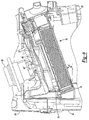
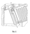
- the intake port 74 may be covered by a filter assembly 76 situated in a filter housing 78 of the vacuum head 64.
- the filter housing 78 may include a ramp 80 that may influence the filter assembly 76 toward and into engagement with an opening of the intake port 74.
- the ramp 80 provided on the interior surface of the filter housing 78 directs the filter assembly 76 in an upward direction so that a continuous gasket 82 provided around the perimeter of the filter engages a projecting rib 84 surrounding the intake opening 74 to provide a sealed connection between the filter assembly 76 and the intake opening 74.
- the gasket 82 is also shown in Figure 10 engaging the projecting rib 84 at the proximal end of the filter assembly 76.
- the motor 66 when powered up, may rotate the suction fan 68 to draw air through a suction inlet 85 into the canister 62, from the canister 62 through the filter assembly 76, through the intake port 74 and into the fan chamber 70.
- the suction fan 68 may push the air in the fan chamber 70 through the exhaust port 72 and out of the vacuum 60.
- the filter assembly 76 may include a frame 90 supporting a panel filter 92.
- the panel filter 92 may be a corrugated paper filter having a plastic, elastomeric or rubber frame portion 96 surrounding the corrugated paper filter.
- the frame portion 96 can include a recess 97 therein for receiving the gasket 82 therein.
- the gasket 82 and frame portion 96 can be integrally formed in order to eliminate additional components.
- the combined filter frame and gasket can be formed from a soft elastomeric material in order to encourage a sealing engagement between the gasket and the projecting portion 84 surrounding the intake passage 74.
- the panel filter 92 may be fabricated from numerous and alternative materials that are well known in the art.
- the panel filter 92 may include an input side 92a that faces away from the intake port 74 and an output side 92b that faces into the intake port 74.
- the tray frame 90 may include a handle 100.
- the frame 90 and the handle 100 may be of a unitary one-piece construction.
- the frame 90 and the handle 100 may be separate and distinct components that are assembled together.
- the frame 90 may be fabricated from a material with sufficient rigidity to allow a user a grasp the handle 100 and shake and/or bang the filter assembly 76 to clean the filter 92.
- the frame 90 may be fabricated from plastic materials, and/or numerous and varied alternative materials that are well known in the art.
- the filter assembly 76 has a rectangular shape. However, the filter assembly 76 may have any geometric shape that extends across and covers the intake port 74.
- the filter 76 may be accessed via the handle 100 which is exposed to the exterior of the vacuum 60 as illustrated in Figure 5.
- the filter assembly 76 is slidably received within the filter housing 78 as illustrated in Figure 8.
- the insertion direction of the removable filter tray 76 can be disposed at an angle ⁇ 1 which can be between 10 and 45 degrees relative to horizontal an angle of.
- the filter housing 78 of the vacuum head 64 may extend downward into the canister 62 at the filter housing's most inward end.
- the angled orientation of the filter tray assembly 76 thus allows the motor 66 and suction fan 68 to be oriented such that the drive shaft 67 of the motor 66 is disposed at the angle ⁇ 2 relative to vertical, as illustrated in Figure 9.
- the angel ⁇ 2 can be between 10 and 45 degrees relative to vertical, or if preferred, out of line.
- the angles ⁇ 1 and ⁇ 2 can be the same or approximately the same as one another although they can also be varied from one another.
- the angled orientation of the filter tray assembly 76, the electric motor 66 and suction fan 68 allows the overall stack height of the motor, fan and filter to be reduced in the vertical direction in order to minimize the overall height of the vacuum 60. Furthermore, the angled orientation of the filter assembly 76 allows the filter to be oriented more inline with the suction inlet 85 of the canister 62, as illustrated in Figure 9.
- the filter housing 78 can be provided with projecting ribs 106, which engage a corresponding projecting rib 108 provided on the surface of the tray 90.
- the projecting ribs 106 and 108 engage one another in order to secure the tray 90 within the filter housing 78.
- the ribs 106, 108 provide the user with a tactile indicator letting them know that the tray 90 is properly inserted into the filter housing 78.
- Additional seals 110 can be provided for sealingly engaging the handle portion of the tray against the opening leading into the filter housing 78. This sealed connection prevents air from being drawn into the vacuum around the opening of the tray housing thus, eliminating undesirable noises and reductions in vacuum pressure utilized for picking up debris.
Landscapes
- Engineering & Computer Science (AREA)
- Mechanical Engineering (AREA)
- Filters For Electric Vacuum Cleaners (AREA)
Applications Claiming Priority (2)
| Application Number | Priority Date | Filing Date | Title |
|---|---|---|---|
| US85994406P | 2006-11-20 | 2006-11-20 | |
| US11/870,822 US7797791B2 (en) | 2006-11-20 | 2007-10-11 | Vacuum with panel filter |
Publications (3)
| Publication Number | Publication Date |
|---|---|
| EP1922970A2 true EP1922970A2 (de) | 2008-05-21 |
| EP1922970A3 EP1922970A3 (de) | 2009-07-08 |
| EP1922970B1 EP1922970B1 (de) | 2013-07-10 |
Family
ID=39049632
Family Applications (1)
| Application Number | Title | Priority Date | Filing Date |
|---|---|---|---|
| EP07121077.7A Not-in-force EP1922970B1 (de) | 2006-11-20 | 2007-11-20 | Staubsauger mit Plattenfilter |
Country Status (2)
| Country | Link |
|---|---|
| US (1) | US7797791B2 (de) |
| EP (1) | EP1922970B1 (de) |
Cited By (3)
| Publication number | Priority date | Publication date | Assignee | Title |
|---|---|---|---|---|
| WO2014019620A1 (de) * | 2012-08-01 | 2014-02-06 | Alfred Kärcher Gmbh & Co. Kg | Selbstfahrende bodenreinigungsmaschine mit filtersystemmodul |
| EP3498141A1 (de) * | 2017-12-15 | 2019-06-19 | Hilti Aktiengesellschaft | Filterkassette |
| WO2022157469A1 (en) * | 2021-01-22 | 2022-07-28 | Dyson Technology Limited | A filter arrangement for a vacuum cleaning appliance |
Families Citing this family (23)
| Publication number | Priority date | Publication date | Assignee | Title |
|---|---|---|---|---|
| KR20090046052A (ko) * | 2007-11-05 | 2009-05-11 | 삼성광주전자 주식회사 | 배기장치 및 이를 포함하는 진공청소기 |
| CA2687871C (en) * | 2008-12-08 | 2018-01-02 | Emerson Electric Co. | Slide out drum with filter for a wet/dry vacuum appliance |
| US8191343B1 (en) * | 2009-06-26 | 2012-06-05 | Hydro-Gear Limited Partnership | Systems and methods for cooling a controller assembly |
| DE102010040664A1 (de) * | 2010-09-13 | 2012-03-15 | Alfred Kärcher Gmbh & Co. Kg | Saugreinigungsvorrichtung |
| US9121638B2 (en) * | 2012-03-26 | 2015-09-01 | Dri-Eaz Products, Inc. | Surface dryers producing uniform exit velocity profiles, and associated systems and methods |
| US9155433B2 (en) | 2012-11-27 | 2015-10-13 | Panasonic Corporation Of North America | Floor cleaning apparatus with filter drawer |
| WO2014176233A1 (en) | 2013-04-22 | 2014-10-30 | Techtronic Floor Care Technology Limited | Vacuum cleaner filter housing |
| WO2017200344A1 (ko) | 2016-05-20 | 2017-11-23 | 엘지전자 주식회사 | 로봇 청소기 |
| WO2017200353A1 (ko) | 2016-05-20 | 2017-11-23 | 엘지전자 주식회사 | 로봇 청소기 |
| US10524628B2 (en) | 2016-05-20 | 2020-01-07 | Lg Electronics Inc. | Autonomous cleaner |
| US10463221B2 (en) * | 2016-05-20 | 2019-11-05 | Lg Electronics Inc. | Autonomous cleaner |
| US10481611B2 (en) | 2016-05-20 | 2019-11-19 | Lg Electronics Inc. | Autonomous cleaner |
| US10420448B2 (en) | 2016-05-20 | 2019-09-24 | Lg Electronics Inc. | Autonomous cleaner |
| US10342400B2 (en) | 2016-05-20 | 2019-07-09 | Lg Electronics Inc. | Autonomous cleaner |
| EP3459419B1 (de) | 2016-05-20 | 2022-10-26 | LG Electronics Inc. | Roboterreiniger |
| WO2017200351A1 (ko) | 2016-05-20 | 2017-11-23 | 엘지전자 주식회사 | 로봇 청소기 |
| US10362916B2 (en) | 2016-05-20 | 2019-07-30 | Lg Electronics Inc. | Autonomous cleaner |
| WO2017200350A1 (ko) | 2016-05-20 | 2017-11-23 | 엘지전자 주식회사 | 로봇 청소기 |
| KR102258616B1 (ko) | 2018-01-10 | 2021-05-28 | 주식회사 엘지화학 | 반도체 패키지용 절연층 제조방법 및 이에 의해 형성된 반도체 패키지용 절연층 |
| CA3060770A1 (en) * | 2018-10-30 | 2020-04-30 | Shop Vac Corporation | Filter system for a vacuum cleaner |
| USD998923S1 (en) * | 2022-01-11 | 2023-09-12 | Beijing Roborock Technology Co., Ltd. | Dust filter for cleaning robot |
| CA212644S (en) * | 2022-01-24 | 2023-03-02 | Beijing Roborock Technology Co Ltd | Dust filter for cleaning robot |
| US12533619B1 (en) * | 2025-05-16 | 2026-01-27 | Groove Technologies, Llc | Cabin air filter removal and installation tool and method of using the same |
Family Cites Families (24)
| Publication number | Priority date | Publication date | Assignee | Title |
|---|---|---|---|---|
| US3570222A (en) | 1969-05-13 | 1971-03-16 | Singer Co | Wet or dry shop vacuum cleaner |
| DE2944749A1 (de) | 1979-11-06 | 1981-05-14 | Rommag P. Wörwag & Co., Romanshorn | Staubsauger |
| US4776060A (en) * | 1987-05-11 | 1988-10-11 | Jiing Lai Chang | Automatic termination and alarm structure for motors used in versatile vacuum cleaner |
| US5150499A (en) * | 1990-11-16 | 1992-09-29 | Shop Vac Corporation | Static electric discharge for dust collector |
| US5829092A (en) | 1996-09-23 | 1998-11-03 | Hobbs; Roy | Vacuum cleaner |
| FR2776908B1 (fr) | 1998-04-02 | 2000-06-09 | Seb Sa | Appareil electrique recuperateur de dechets |
| US6210469B1 (en) | 1999-02-26 | 2001-04-03 | Donaldson Company, Inc. | Air filter arrangement having first and second filter media dividing a housing and methods |
| US6378165B1 (en) | 2000-02-17 | 2002-04-30 | Emerson Electric Co. | Pull handle with interlocking mounting mechanism for wet/dry vacuum appliance |
| KR100433408B1 (ko) | 2002-03-05 | 2004-05-31 | 삼성광주전자 주식회사 | 진공청소기 |
| KR100437116B1 (ko) | 2002-05-22 | 2004-06-23 | 삼성광주전자 주식회사 | 진공청소기 |
| DE60334381D1 (de) * | 2002-07-25 | 2010-11-11 | Toshiba Tec Kk | Staubsauger |
| US7305735B2 (en) | 2002-10-11 | 2007-12-11 | Panasonic Corporation Of North America | Vacuum cleaner equipped with dirt cup and separate filter drawer |
| US7185394B2 (en) | 2002-11-07 | 2007-03-06 | Panasonic Corporation Of North America | Dirt cup assembly with attachable and detachable external filter holder |
| US7653963B2 (en) | 2002-11-12 | 2010-02-02 | Black & Decker Inc. | AC/DC hand portable wet/dry vacuum having improved portability and convenience |
| KR100485714B1 (ko) | 2003-04-04 | 2005-04-28 | 삼성광주전자 주식회사 | 백레스 진공청소기 |
| KR100470561B1 (ko) | 2003-04-28 | 2005-03-10 | 삼성광주전자 주식회사 | 진공청소기용 사이클론 집진장치 |
| US7008465B2 (en) | 2003-06-19 | 2006-03-07 | Donaldson Company, Inc. | Cleanable high efficiency filter media structure and applications for use |
| GB2418600B (en) | 2003-07-22 | 2006-11-22 | Panasonic Corp North America | Bagless vacuum cleaner system |
| US7614113B2 (en) | 2003-07-31 | 2009-11-10 | Panasonic Corporation Of North America | Motor enclosure for a vacuum cleaner |
| DE602004025846D1 (de) * | 2003-12-08 | 2010-04-15 | Shop Vac Corp | Staubsauger mit wieder aufladbarer batterie |
| US7235121B2 (en) | 2003-12-26 | 2007-06-26 | West Timothy J | Externally removable vacuum cleaner filter apparatus |
| DE102004046382B4 (de) | 2004-09-24 | 2007-12-13 | Stein & Co Gmbh | Gehäuseunterteil für Handstaubsauger |
| AU2006218540B2 (en) * | 2005-02-28 | 2011-03-31 | Shop Vac Corporation | Dual-tank vacuum cleaner |
| KR20060128388A (ko) | 2005-06-10 | 2006-12-14 | 엘지전자 주식회사 | 진공 청소기 |
-
2007
- 2007-10-11 US US11/870,822 patent/US7797791B2/en active Active
- 2007-11-20 EP EP07121077.7A patent/EP1922970B1/de not_active Not-in-force
Non-Patent Citations (1)
| Title |
|---|
| None |
Cited By (6)
| Publication number | Priority date | Publication date | Assignee | Title |
|---|---|---|---|---|
| WO2014019620A1 (de) * | 2012-08-01 | 2014-02-06 | Alfred Kärcher Gmbh & Co. Kg | Selbstfahrende bodenreinigungsmaschine mit filtersystemmodul |
| EP3498141A1 (de) * | 2017-12-15 | 2019-06-19 | Hilti Aktiengesellschaft | Filterkassette |
| WO2019115157A1 (de) * | 2017-12-15 | 2019-06-20 | Hilti Aktiengesellschaft | Filterkassette |
| US12414662B2 (en) | 2017-12-15 | 2025-09-16 | Hilti Aktiengesellschaft | Filter cassette |
| WO2022157469A1 (en) * | 2021-01-22 | 2022-07-28 | Dyson Technology Limited | A filter arrangement for a vacuum cleaning appliance |
| US12514416B2 (en) | 2021-01-22 | 2026-01-06 | Dyson Technology Limited | Filter arrangement for a vacuum cleaning appliance |
Also Published As
| Publication number | Publication date |
|---|---|
| EP1922970A3 (de) | 2009-07-08 |
| EP1922970B1 (de) | 2013-07-10 |
| US7797791B2 (en) | 2010-09-21 |
| US20080115315A1 (en) | 2008-05-22 |
Similar Documents
| Publication | Publication Date | Title |
|---|---|---|
| US7797791B2 (en) | Vacuum with panel filter | |
| KR100917853B1 (ko) | 이중 탱크 진공 청소기 | |
| EP1674017B1 (de) | Staubsammelanordnung und Staubsauger mit derselben | |
| US7900316B2 (en) | Filter for a vacuum cleaner | |
| US6442792B1 (en) | Vacuum cleaner | |
| US20060156508A1 (en) | Vacuum cleaner with cyclonic separating dirt cup and dirt cup door | |
| CA2660913C (en) | Easy access filter assembly for a wet/dry vacuum appliance | |
| MXPA01008886A (es) | Aspirador de polvo con escape soplador desprendible con silenciador. | |
| CN1310655A (zh) | 带有吸尘装置的手工工具机 | |
| EP1495710A3 (de) | Staubsauger | |
| CN107837038A (zh) | 真空吸尘器 | |
| JP2013141514A (ja) | 電気掃除機 | |
| CN201123780Y (zh) | 真空吸尘器 | |
| US20070039124A1 (en) | Exhaust structure of vacuum cleaner | |
| JP5460495B2 (ja) | 電気掃除機 | |
| US20120210685A1 (en) | Apparatus of centrifugal fan and a dust-collecting module using the same | |
| CN213030578U (zh) | 多风机吸尘器 | |
| RU2728134C1 (ru) | Напольный пылесос | |
| CN100515306C (zh) | 电动吸尘器 | |
| CN213030582U (zh) | 带有抖尘功能的桶式吸尘器 | |
| EP4452031B1 (de) | Saugrohranordnung für eine staubsauger | |
| US20240324831A1 (en) | Surface cleaner | |
| JP4269315B2 (ja) | 電気掃除機 | |
| CN211022466U (zh) | 收纳盒及清洁机器人 | |
| KR100338889B1 (ko) | 전기청소기 |
Legal Events
| Date | Code | Title | Description |
|---|---|---|---|
| PUAI | Public reference made under article 153(3) epc to a published international application that has entered the european phase |
Free format text: ORIGINAL CODE: 0009012 |
|
| AK | Designated contracting states |
Kind code of ref document: A2 Designated state(s): AT BE BG CH CY CZ DE DK EE ES FI FR GB GR HU IE IS IT LI LT LU LV MC MT NL PL PT RO SE SI SK TR |
|
| AX | Request for extension of the european patent |
Extension state: AL BA HR MK RS |
|
| PUAL | Search report despatched |
Free format text: ORIGINAL CODE: 0009013 |
|
| AK | Designated contracting states |
Kind code of ref document: A3 Designated state(s): AT BE BG CH CY CZ DE DK EE ES FI FR GB GR HU IE IS IT LI LT LU LV MC MT NL PL PT RO SE SI SK TR |
|
| AX | Request for extension of the european patent |
Extension state: AL BA HR MK RS |
|
| 17P | Request for examination filed |
Effective date: 20090806 |
|
| 17Q | First examination report despatched |
Effective date: 20090903 |
|
| AKX | Designation fees paid |
Designated state(s): DE GB IT SE |
|
| GRAP | Despatch of communication of intention to grant a patent |
Free format text: ORIGINAL CODE: EPIDOSNIGR1 |
|
| GRAS | Grant fee paid |
Free format text: ORIGINAL CODE: EPIDOSNIGR3 |
|
| GRAA | (expected) grant |
Free format text: ORIGINAL CODE: 0009210 |
|
| AK | Designated contracting states |
Kind code of ref document: B1 Designated state(s): DE GB IT SE |
|
| REG | Reference to a national code |
Ref country code: GB Ref legal event code: FG4D |
|
| REG | Reference to a national code |
Ref country code: DE Ref legal event code: R096 Ref document number: 602007031522 Country of ref document: DE Effective date: 20130905 |
|
| PG25 | Lapsed in a contracting state [announced via postgrant information from national office to epo] |
Ref country code: SE Free format text: LAPSE BECAUSE OF FAILURE TO SUBMIT A TRANSLATION OF THE DESCRIPTION OR TO PAY THE FEE WITHIN THE PRESCRIBED TIME-LIMIT Effective date: 20130710 |
|
| PLBE | No opposition filed within time limit |
Free format text: ORIGINAL CODE: 0009261 |
|
| STAA | Information on the status of an ep patent application or granted ep patent |
Free format text: STATUS: NO OPPOSITION FILED WITHIN TIME LIMIT |
|
| PG25 | Lapsed in a contracting state [announced via postgrant information from national office to epo] |
Ref country code: IT Free format text: LAPSE BECAUSE OF FAILURE TO SUBMIT A TRANSLATION OF THE DESCRIPTION OR TO PAY THE FEE WITHIN THE PRESCRIBED TIME-LIMIT Effective date: 20130710 |
|
| 26N | No opposition filed |
Effective date: 20140411 |
|
| REG | Reference to a national code |
Ref country code: DE Ref legal event code: R097 Ref document number: 602007031522 Country of ref document: DE Effective date: 20140411 |
|
| PGFP | Annual fee paid to national office [announced via postgrant information from national office to epo] |
Ref country code: GB Payment date: 20191122 Year of fee payment: 13 |
|
| PGFP | Annual fee paid to national office [announced via postgrant information from national office to epo] |
Ref country code: DE Payment date: 20201110 Year of fee payment: 14 |
|
| GBPC | Gb: european patent ceased through non-payment of renewal fee |
Effective date: 20201120 |
|
| PG25 | Lapsed in a contracting state [announced via postgrant information from national office to epo] |
Ref country code: GB Free format text: LAPSE BECAUSE OF NON-PAYMENT OF DUE FEES Effective date: 20201120 |
|
| REG | Reference to a national code |
Ref country code: DE Ref legal event code: R119 Ref document number: 602007031522 Country of ref document: DE |
|
| PG25 | Lapsed in a contracting state [announced via postgrant information from national office to epo] |
Ref country code: DE Free format text: LAPSE BECAUSE OF NON-PAYMENT OF DUE FEES Effective date: 20220601 |