EP1923155A1 - Verfahren zum Herstellen von zusammengesetzten Sintermaschinenbauteilen - Google Patents
Verfahren zum Herstellen von zusammengesetzten Sintermaschinenbauteilen Download PDFInfo
- Publication number
- EP1923155A1 EP1923155A1 EP07021509A EP07021509A EP1923155A1 EP 1923155 A1 EP1923155 A1 EP 1923155A1 EP 07021509 A EP07021509 A EP 07021509A EP 07021509 A EP07021509 A EP 07021509A EP 1923155 A1 EP1923155 A1 EP 1923155A1
- Authority
- EP
- European Patent Office
- Prior art keywords
- inner member
- pillars
- interference
- fitted
- outer member
- Prior art date
- Legal status (The legal status is an assumption and is not a legal conclusion. Google has not performed a legal analysis and makes no representation as to the accuracy of the status listed.)
- Granted
Links
- 238000000034 method Methods 0.000 title claims abstract description 32
- 238000004519 manufacturing process Methods 0.000 title claims abstract description 16
- 239000002131 composite material Substances 0.000 title claims abstract description 13
- 239000000843 powder Substances 0.000 claims abstract description 18
- XEEYBQQBJWHFJM-UHFFFAOYSA-N Iron Chemical compound [Fe] XEEYBQQBJWHFJM-UHFFFAOYSA-N 0.000 claims abstract description 16
- 238000005245 sintering Methods 0.000 claims abstract description 14
- 229910052742 iron Inorganic materials 0.000 claims abstract description 6
- 239000011812 mixed powder Substances 0.000 claims abstract description 4
- 239000000956 alloy Substances 0.000 claims abstract description 3
- 229910045601 alloy Inorganic materials 0.000 claims abstract description 3
- 239000000203 mixture Substances 0.000 claims description 11
- 239000000969 carrier Substances 0.000 description 5
- 238000009792 diffusion process Methods 0.000 description 5
- 239000000314 lubricant Substances 0.000 description 5
- 230000003247 decreasing effect Effects 0.000 description 4
- 238000012360 testing method Methods 0.000 description 4
- 230000005540 biological transmission Effects 0.000 description 3
- 238000005219 brazing Methods 0.000 description 3
- 239000004615 ingredient Substances 0.000 description 3
- XOOUIPVCVHRTMJ-UHFFFAOYSA-L zinc stearate Chemical compound [Zn+2].CCCCCCCCCCCCCCCCCC([O-])=O.CCCCCCCCCCCCCCCCCC([O-])=O XOOUIPVCVHRTMJ-UHFFFAOYSA-L 0.000 description 3
- OKTJSMMVPCPJKN-UHFFFAOYSA-N Carbon Chemical compound [C] OKTJSMMVPCPJKN-UHFFFAOYSA-N 0.000 description 2
- 239000000654 additive Substances 0.000 description 2
- 230000000996 additive effect Effects 0.000 description 2
- 238000013459 approach Methods 0.000 description 2
- 238000005255 carburizing Methods 0.000 description 2
- 230000002093 peripheral effect Effects 0.000 description 2
- 239000012071 phase Substances 0.000 description 2
- RYGMFSIKBFXOCR-UHFFFAOYSA-N Copper Chemical compound [Cu] RYGMFSIKBFXOCR-UHFFFAOYSA-N 0.000 description 1
- 239000001273 butane Substances 0.000 description 1
- 229910052799 carbon Inorganic materials 0.000 description 1
- 230000006835 compression Effects 0.000 description 1
- 238000007906 compression Methods 0.000 description 1
- 238000005520 cutting process Methods 0.000 description 1
- 238000013461 design Methods 0.000 description 1
- 238000009826 distribution Methods 0.000 description 1
- 230000000694 effects Effects 0.000 description 1
- 229910002804 graphite Inorganic materials 0.000 description 1
- 239000010439 graphite Substances 0.000 description 1
- 239000007791 liquid phase Substances 0.000 description 1
- 238000003754 machining Methods 0.000 description 1
- 239000000463 material Substances 0.000 description 1
- 239000002184 metal Substances 0.000 description 1
- 229910052751 metal Inorganic materials 0.000 description 1
- IJDNQMDRQITEOD-UHFFFAOYSA-N n-butane Chemical compound CCCC IJDNQMDRQITEOD-UHFFFAOYSA-N 0.000 description 1
- OFBQJSOFQDEBGM-UHFFFAOYSA-N n-pentane Natural products CCCCC OFBQJSOFQDEBGM-UHFFFAOYSA-N 0.000 description 1
- 238000003825 pressing Methods 0.000 description 1
- 230000002265 prevention Effects 0.000 description 1
- 238000012545 processing Methods 0.000 description 1
Images


Classifications
-
- B—PERFORMING OPERATIONS; TRANSPORTING
- B22—CASTING; POWDER METALLURGY
- B22F—WORKING METALLIC POWDER; MANUFACTURE OF ARTICLES FROM METALLIC POWDER; MAKING METALLIC POWDER; APPARATUS OR DEVICES SPECIALLY ADAPTED FOR METALLIC POWDER
- B22F7/00—Manufacture of composite layers, workpieces, or articles, comprising metallic powder, by sintering the powder, with or without compacting wherein at least one part is obtained by sintering or compression
- B22F7/02—Manufacture of composite layers, workpieces, or articles, comprising metallic powder, by sintering the powder, with or without compacting wherein at least one part is obtained by sintering or compression of composite layers
-
- B—PERFORMING OPERATIONS; TRANSPORTING
- B22—CASTING; POWDER METALLURGY
- B22F—WORKING METALLIC POWDER; MANUFACTURE OF ARTICLES FROM METALLIC POWDER; MAKING METALLIC POWDER; APPARATUS OR DEVICES SPECIALLY ADAPTED FOR METALLIC POWDER
- B22F5/00—Manufacture of workpieces or articles from metallic powder characterised by the special shape of the product
- B22F5/08—Manufacture of workpieces or articles from metallic powder characterised by the special shape of the product of toothed articles, e.g. gear wheels; of cam discs
-
- B—PERFORMING OPERATIONS; TRANSPORTING
- B22—CASTING; POWDER METALLURGY
- B22F—WORKING METALLIC POWDER; MANUFACTURE OF ARTICLES FROM METALLIC POWDER; MAKING METALLIC POWDER; APPARATUS OR DEVICES SPECIALLY ADAPTED FOR METALLIC POWDER
- B22F5/00—Manufacture of workpieces or articles from metallic powder characterised by the special shape of the product
- B22F5/10—Manufacture of workpieces or articles from metallic powder characterised by the special shape of the product of articles with cavities or holes, not otherwise provided for in the preceding subgroups
- B22F5/106—Tube or ring forms
-
- B—PERFORMING OPERATIONS; TRANSPORTING
- B22—CASTING; POWDER METALLURGY
- B22F—WORKING METALLIC POWDER; MANUFACTURE OF ARTICLES FROM METALLIC POWDER; MAKING METALLIC POWDER; APPARATUS OR DEVICES SPECIALLY ADAPTED FOR METALLIC POWDER
- B22F7/00—Manufacture of composite layers, workpieces, or articles, comprising metallic powder, by sintering the powder, with or without compacting wherein at least one part is obtained by sintering or compression
- B22F7/06—Manufacture of composite layers, workpieces, or articles, comprising metallic powder, by sintering the powder, with or without compacting wherein at least one part is obtained by sintering or compression of composite workpieces or articles from parts, e.g. to form tipped tools
- B22F7/062—Manufacture of composite layers, workpieces, or articles, comprising metallic powder, by sintering the powder, with or without compacting wherein at least one part is obtained by sintering or compression of composite workpieces or articles from parts, e.g. to form tipped tools involving the connection or repairing of preformed parts
-
- Y—GENERAL TAGGING OF NEW TECHNOLOGICAL DEVELOPMENTS; GENERAL TAGGING OF CROSS-SECTIONAL TECHNOLOGIES SPANNING OVER SEVERAL SECTIONS OF THE IPC; TECHNICAL SUBJECTS COVERED BY FORMER USPC CROSS-REFERENCE ART COLLECTIONS [XRACs] AND DIGESTS
- Y10—TECHNICAL SUBJECTS COVERED BY FORMER USPC
- Y10T—TECHNICAL SUBJECTS COVERED BY FORMER US CLASSIFICATION
- Y10T29/00—Metal working
- Y10T29/49—Method of mechanical manufacture
- Y10T29/49826—Assembling or joining
Definitions
- the present invention relates to processes for manufacturing machine components such as carriers for a planetary gear system that is included in an automatic transmission of an automobile (hereinafter called a "planetary carrier") by a powdered metallurgical method.
- the present invention relates to a process for manufacturing composite sintered machine components in which a compact (an inner member) having plural pillars and another compact (an outer member) having holes corresponding to the pillars are tightly fitted and are sintered so as to bond each other.
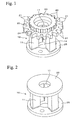
- planetary carriers differ in design according to the type of transmission, they usually comprise a cylindrical drum, flanges formed at both ends or at the middle of the drum, and a center shaft hole into which a shaft of a transmission is inserted.
- the drum is formed with plural openings for holding planetary gears (not shown in the figure).
- Fig. 1 shows an example of such a planetary carrier, and each of the plural (in this case, three) openings 11 formed on a drum 10 is rotatably mounted with a planetary gear (not shown in the figure).
- the planetary gear is engaged with a sun gear of a shaft (not shown in the figure) inserted into a center shaft hole 12 of the drum 10 at the inner side of the drum 10, and it is engaged with a ring gear (not shown in the figure) at the outer side of the drum 10.
- Flanges 20 and 25 are formed at the upper end and the lower end of the drum 10, and the flange 20 in the upper side of the figure is formed with spur teeth 21 for transmitting a torque.
- a boss 23 is concentrically formed on the upper surface of the upper flange 20, and the boss 23 is formed with a spline 24 for engaging a clutch system (not shown in the figure).
- planetary carriers since a planetary carrier has such a complicated structure, if it is mass-produced by machining process such as cutting, great number of processing steps are required, whereby there are disadvantages in cost and accuracy of shape and size. Therefore, planetary carriers are usually manufactured by a powdered metallurgical method that is suitable for manufacturing products uniformly in large quantities; however, in the case of planetary carriers having openings forming undercuts, which are provided on a drum, it is difficult to form them unitarily in a die.
- a required shape is divided into several portions, and after the portions are individually formed and sintered, they are combined to form the required shape.
- a planetary carrier will be described based on a schematic shape shown in Fig. 2 hereinafter.
- the planetary carrier shown in Fig. 2 has a simple flange 20 at the upper end and a simple flange 25 at the lower end on a cylindrical drum 10, and it has three openings 11 at equal intervals in the circumferential direction of the drum 10.
- the spur teeth 21 and the boss 23 of the flange 20 are omitted.
- the planetary carrier is divided into two portions by separating one flange 20 (25) from the drum 10.
- a planetary carrier is divided into a disk-shaped member 30 (corresponding to the flange 20 in Fig. 2) having a center shaft hole 31 and a body member 40, and the disk-shaped member 30 and the body member 40 are individually formed and sintered so as to make two portions. Then, the sintered disk-shaped member 30 and the sintered body member 40 are mated and bonded by brazing at the divided surfaces.
- Fig. 3A is a top view of the disk-shaped member 30
- Fig. 3B is a longitudinal sectional view of the disk-shaped member 30
- Fig. 3C is a top view of the body member 40
- Fig. 3D is a longitudinal sectional view of the body member 40
- FIG. 3E shows a condition in which the disk-shaped member 30 and the body member 40 are bonded, that is, it is a top view showing a condition shown in Fig. 2, and Fig. 3F is a longitudinal sectional view of the condition shown in Fig. 3E.
- the drum of the body member 40 has relatively large openings, and the appearance thereof may be described as "three fan-shaped pillars". Therefore, the drum will be called plural (three) pillars 42 hereinafter. That is, the body member 40 has a shape in which a disk-shaped portion 47 having a center shaft hole 41 is integrally fixed to ends of the plural pillars 42.
- the bonding strength of the disk-shaped member 30 and the body member 40 mainly depends on the strength of the brazing metal, whereby it is difficult to obtain the required level of strength.
- a body member 40 is a compact (inner member) in which fan-shaped pillars 42 are integrally formed
- a disk-shaped member 30 is a compact (outer member) in which holes 32 corresponding to the shape of the pillars 42 of the body member 40 are formed in connection with a center shaft hole 31. Then, the body member 40 and the disk-shaped member 30 are sintered in a condition in which the pillars 42 of the body portion 40 are tightly fitted to the holes 32 of the disk-shaped portion 30.
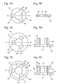
- Fig. 4A is a top view of the disk-shaped member 30
- Fig. 4B is a longitudinal sectional view of the disk-shaped member 30
- Fig. 4C is a top view of the body member 40
- Fig. 4D is a longitudinal sectional view of the body member 40
- Fig. 4E is a top view showing a condition in which the pillars 42 of the body member 40 are tightly fitted to the holes 32 of the disk-shaped member 30
- Fig. 4F is a longitudinal sectional view showing the condition shown in Fig. 4E.
- the above-mentioned misalignments of the centers and the phases do not occur, but the bonding surfaces of the inner member and the outer member tend to be insufficiently bonded each other, and the required level of the bonding strength may not be obtained. The reason for this is described hereinafter.
- the contacting surface of the disk-shaped member 30 and the body member 40 that is, the contacting surface of the pillars 42 and the inner surface of the holes 32 into which the pillars 42 are inserted, is not completely closed, and the contacting surface is open to the center shaft hole 31. Therefore, even though the amount of thermal expansion of the body member 40 is set to be relatively grater than that of the disk-shaped member 30 as in the methods disclosed in the patent documents 1 to 3, pressure due to the expansion of the pillars 42 impinges on the side of the center shaft hole 31, whereby the contacting surface of the disk-shaped member 30 and the body member 40 may not tightly contact, and the bonding strength is decreased.
- both sides 45 which are the sides of the pillars 42 provided to the body member 40 (inner member), are modified so as to have a refractile surface (stepped shape), and the outline of the holes 32 provided to the disk-shaped member 30 (outer member) is modified so as to have a shape corresponding to the sides of the pillars 42 so as to secure the bonding strength.
- the effect of strain based on the difference of the amount of thermal expansion occurring at the bonding surface of the pillars 42 and the inner surface of the holes 32 during sintering is decreased, and the expansion pressure of the pillars is prevented from escaping to the side of the center shaft hole 31 because the pillars 42 are thin at the bent portion, whereby the bonding strength is secured.
- the technique disclosed in the patent document 4 is an elaboration of the technique disclosed in the patent documents 1 to 3, and it is based on a condition in which the amount of thermal expansion of the body member 40 is greater than that of the disk-shaped member 30. In this case, not only the pillars 42, but also the entire body member 40 can expand, and even when the expansion of the pillars 42 is restricted by the holes 32 of the disk-shaped member 30, a deflection may occur because the remaining portion expands, and the degree of parallelization of the disk-shaped member 30 and the body member 40 is thereby lost.
- the disk-shaped member 30 has a thin portion 38 between an outer periphery 37 and the hole 32 of the disk-shaped member 30 shown in Figs. 4A to 4F and Figs. 5A to 5F, and the thin portion 38 deforms according to the expansion of the body member 40, especially, the pillars 42, whereby there are disadvantages in which the degree of circularity of the sintered disk-shaped member 30 (in the planetary carrier shown in Fig. 1, the dimensional accuracy of the teeth) is inferior, and fracture may occur at the thin portion 38.
- An object of the present invention is to provide a process for manufacturing composite sintered machine components such as planetary carriers.
- the composite sintered machine components when a compact of an outer member having plural pillars and a compact of an inner member having hole portions corresponding to the pillars of the compact of the outer member are tightly fitted and sintered so as to bond each other, the outer member and the inner member can be bonded with a sufficient bonding strength without utilizing a difference in thermal expansion thereof in a high temperature range during sintering, and deflections of the outer member and the inner member, and deformations and fractures of thin portion of the outer member can be avoided.
- the present invention provides a process for manufacturing composite sintered machine components.
- the composite sintered machine component has an approximately cylindrical inner member having pillars arranged in a circumferential direction at equal intervals and a center shaft hole surrounded by the pillars, and it also has an approximately disk-shaped outer member having holes corresponding to the pillars of the inner member and a center shaft hole which corresponds to the center shaft hole of the inner member and is connected to the holes.
- the process comprises compacting the inner member and the outer member individually with an iron-based alloy powder or an iron-based mixed powder so as to obtain compacts of the inner member and the outer member, tightly fitting the pillars of the inner member into the holes of the outer member, and sintering the inner member and the outer member and maintaining the above condition so as to bond them together.
- a circumferential side surface facing the circumferential direction of the pillars of the inner member and a circumferential side surface facing the circumferential direction of the hole of the outer member are interference fitted at 0 to 0.03 mm of interference.
- a radial side surface facing the radial direction of the pillars of the inner member and a radial side surface facing the radial direction of the hole of the outer member are interference fitted at not more than 0.01 mm of the interference or are through fitted (interference is minus).
- the radial side surface of the pillar of the inner member and the radial side surface of the convex portion of the outer member are tightly fitted at 0 mm of the interference or are through fitted (interference is minus).
- the circumferential side surface of the pillars of the inner member is formed in a range -30 to 30° with respect to a radial line extending in a radial direction.
- at least one concave portion is formed on the radial side surface of the pillars of the inner member, a convex portion corresponding to the concave portion is formed on the hole of the outer member, and each circumferential side surface of the concave portion and the convex portion facing each other is interference fitted at 0 to 0.03 mm of interference.
- the inner compact and the outer compact have the same compositions.
- the circumferential side surface of the pillars of the inner member and the circumferential side surface of the hole of the outer member are interference fitted at 0 to 0.03 mm of the interference, and a sufficient bonding strength is thereby obtained.
- the radial side surface of the pillars and the radial side surface of the hole are interference fitted at not more than 0.01 mm of the interference or are through fitted (interference is minus), whereby a deformation and a fracture of thin portion of the outer member can be avoided.
- the inner member and the outer member can be made from raw powders having the same composition, whereby a step for preparing different raw powders for the inner member and the outer member can be omitted, and an error such as an inappropriate composing of raw powders can be avoided.
- the embodiment shows a process in which a structure shown in Figs. 4A to 4F, that is, each hole 32 of a disk-shaped member 30 of a compact, is tightly fitted and bonded with a pillar 42 of a body member 40 of a compact. Then, in a condition in which the disk-shaped member 30 and the body member 40 are tightly fitted, each circumferential side surface 45 facing the circumferential direction of the pillars 42 and each circumferential side surface 35 facing the circumferential direction of the hole 32 are interference fitted at 0 to 0.03 mm of the interference.
- the circumferential side surface 45 of the pillars 42 and the circumferential side surface 35 of the holes 32 are tightly contacted in the sintering process, and diffusion of raw powders proceeds at the surfaces of the disk-shaped member 30 and the body member 40, and the disk-shaped member 30 and the body member 40 are thereby bonded.
- the compositions of the disk-shaped member 30 and the body member 40 may be selected to differ from each other in amount of thermal expansion in a high temperature range (diffusion temperature range of additive ingredients) during sintering, as disclosed in the patent document 1 to 3.
- the compositions of the disk-shaped member 30 and the body member 40 are preferable to have compositions in which amounts of thermal expansion are equal. That is, instead of preparing a zinc stearate as a powdered lubricant and another powdered lubricant, and arranging raw powders for the disk-shaped member 30 and the body member 40 respectively as disclosed in the patent document 3, raw powders having the same compositions, which include a powder lubricant, can be used.
- the holes 32 are press fitted with the pillars 42, whereby the fitting clearance between the disk-shaped member 30 and the body member 40 is not changed in high temperature range during sintering, and diffusion bonding is performed while maintaining a condition in which the boundary of the disk-shaped member 30 and the body member 40 are tightly contacted.
- the fitting clearance of the disk-shaped member 30 and the body member 40 may be through fitting (the interference is less than 0 mm), they are insufficiently contacted, and sufficient bonding strength cannot be obtained.
- the interference is more than 0.03 mm, the compacts may be broken during press fitting. Therefore, the interference is preferably set to be 0 to 0.03 mm.
- the disk-shaped member 30 and the body member 40 are press fitted in a condition in which the circumferential side surface 45 of the pillars 42 and corresponding circumferential side surface 35 of the holes 32 are coincided with the radial line extending in the radial direction, and the fitting clearance can thereby be minimized.
- the circumferential side surface 45 of the pillars 42 and the corresponding circumferential side surface 35 of the holes 32 are coincided with the radial line extending in the radial direction, if they are largely inclined with respect to the radial line, the stiffness of the disk-shaped member 30 is decreased at press fitting, whereby the disk-shaped member 30 and the body member 40 are difficult to be brought into sufficient contact. Moreover, in this case, deformation of the disk-shaped member 30 at press fitting is large, and it tends to break. Therefore, the circumferential side surface 45 of the pillars 42 and corresponding circumferential side surface 35 of the hole 32 are required to be in a range -30 to 30° with respect to the radial line (0°).
- the circumferential side surface 45 of the pillars 42 and the circumferential side surface 35 of the holes 32 are bonded in the above range with respect to the radial line, whereby a strength with respect to a torsion in rotational direction of a planetary carrier is highly secured.
- the circumferential side surface 45 of the pillars 42 and the circumferential side surface 35 of the hole 32 are bonded with a sufficient bonding strength, whereby a radial side surface 44 of the outer periphery of the pillars 42 and a radial side surface 34 of the hole 32 are bonded with a sufficient strength that is not strong as in the case of the circumferential side surfaces. Accordingly, in the radial side surface 44 of the pillars 42 and the radial side surface 34 of the holes 32, sizes thereof can be selected primarily for prevention of deformation of a thin portion 38 between an outer periphery 37 and the hole 32 of the disk-shaped member 30.
- the disk-shaped member 30 and the body member 40 are interference fitted at not more than 0.01 mm of the interference or are through fitted (interference is minus). In this case, when the interference is more than 0.01 mm, the thin portion 38 tends to break at press fitting.
- the compositions of the disk-shaped member 30 and the body member 40 differ in amount of thermal expansion in a high temperature range during sintering as disclosed in the patent documents 1 to 3, it is preferable that the disk-shaped member 30 and the body member 40 be fitted at 0 mm of interference or be through fitted.
- the radial side surface 44 of the pillars 42 and the radial side surface 34 of the hole 32 may not be bonded as strongly as in the case of the circumferential side surfaces, and the bonding strength thereof may be improved by bonding. From this point of view, when raw powders having exactly the same composition are used for the disk-shaped member 30 and the body member 40, as described above, the disk-shaped member 30 and the body member 40 are expanded respectively, whereby they can be bonded by preventing deformation of the thin portion 38 even when they are interference fitted at not more than 0.01 mm of interference.
- the circumferential side surface 45 of the pillars 42 and the corresponding circumferential side surface 35 of the holes 32 can be bonded with sufficient bonding strength, and the radial side surface 44 of the pillars 42 and corresponding radial side surface 34 of the holes 32 can be bonded, preventing deformation of the thin portion 38 between the outer periphery 37 and the hole 32 of the disk-shaped member 30.
- raw powders having the same composition are used for the disk-shaped member 30 and the body member 40, whereby a step for preparing different raw powders for the inner member and the outer member can be omitted, and an error such as an inappropriate composing of raw powders can be avoided.
- the length of the bonding surface may be elongated.
- a radial side surface 44 of pillars 42 is formed with one or plural concave portions 46
- a hole 32 is formed with a convex portion 36 corresponding to the concave portion 46
- a circumferential side surface 49 of the concave portion 46 and a circumferential side surface 39 of the convex portion 36 are interference fitted at 0 to 0.03 mm of interference and are sintered. Therefore, the length of the bonding surface is increased, and the bonding strength can be further improved.
- Compacts of a body member having the same structure as the body member 40 and a compact of a disk-shaped member having the same structure as the disk-shaped member 30 as shown in Figs. 4A to 4F were formed by the following processes.
- a disk portion 47 was 40 mm in outer diameter
- a center shaft hole 41 was 11 mm in diameter
- the thickness was 6 mm
- pillars 42 were radially arranged at equal intervals in a standing manner at the periphery of the center shaft hole 41.
- the height was 18 mm
- an outer peripheral surface that is, a radial side surface 44 was 14 mm in radius
- an inner peripheral surface was 5.5 mm in radius
- both circumferential side surfaces 45 were fan-shaped in cross section with an open angle of 36°.
- an outer diameter was 34 mm
- a center shaft hole 31 was 11 mm in diameter
- the thickness was 6 mm
- three holes 32 that were connected to the center shaft hole 31 and corresponded to the pillars 42 were formed.
- an interference of the circumferential side surface 45 of the pillars 42 and the circumferential side surface 35 of the holes 32 was modified according to the interference shown in Table 1, and plural (sample numbers 01 to 09) compacts were formed.
- the space between the radial side surface 44 of the pillar 42 and the radial side surface 34 of the hole 32 was set to be 0 mm.
- the compacts were fitted by press fitting the hole 32 of the disk-shaped member 30 with the pillars 42 of the body member 40, and this was sintered at 1130°C for 40 minutes in a carburizing denatured butane gas atmosphere so as to bond each other.
- a breaking test was performed in such a way that the body member 40 was held on a mount by a material test machine, and the disk-shaped member 30 was loaded. The bonding strength measured by the test and the degree of parallelization are also shown in Table 1.
- value (mm) of the degree of parallelization was obtained in such a way that the disk-shaped member 30 of the sintered component was placed with its face down on a flat surface, the distribution of heights of the top surface, which was the bottom surface of the body member 40, was measured, and the lowest value was subtracted from highest value of the height. The lower the value, the greater the degree of parallelization.
Landscapes
- Engineering & Computer Science (AREA)
- Manufacturing & Machinery (AREA)
- Mechanical Engineering (AREA)
- Chemical & Material Sciences (AREA)
- Composite Materials (AREA)
- Materials Engineering (AREA)
- Powder Metallurgy (AREA)
- Ceramic Products (AREA)
Applications Claiming Priority (1)
| Application Number | Priority Date | Filing Date | Title |
|---|---|---|---|
| JP2006305070A JP4721449B2 (ja) | 2006-11-10 | 2006-11-10 | 複合焼結機械部品の製造方法 |
Publications (2)
| Publication Number | Publication Date |
|---|---|
| EP1923155A1 true EP1923155A1 (de) | 2008-05-21 |
| EP1923155B1 EP1923155B1 (de) | 2009-06-24 |
Family
ID=39030997
Family Applications (1)
| Application Number | Title | Priority Date | Filing Date |
|---|---|---|---|
| EP07021509A Not-in-force EP1923155B1 (de) | 2006-11-10 | 2007-11-05 | Verfahren zum Herstellen von zusammengesetzten Sintermaschinenbauteilen |
Country Status (6)
| Country | Link |
|---|---|
| US (2) | US7947219B2 (de) |
| EP (1) | EP1923155B1 (de) |
| JP (1) | JP4721449B2 (de) |
| KR (1) | KR100958971B1 (de) |
| AT (1) | ATE434499T1 (de) |
| DE (1) | DE602007001375D1 (de) |
Cited By (5)
| Publication number | Priority date | Publication date | Assignee | Title |
|---|---|---|---|---|
| WO2010128976A1 (en) * | 2009-05-04 | 2010-11-11 | Gkn Sinter Metals, Llc | Adhesive joining for powder metal components |
| US9144844B2 (en) | 2010-08-11 | 2015-09-29 | Schwabische Huttenwerke Automotive Gmbh | Sintered composite and method for its manufacture |
| CN107243637A (zh) * | 2017-05-08 | 2017-10-13 | 无锡市恒翼通机械有限公司 | 粉末冶金行星架及其制备工艺 |
| CN107511485A (zh) * | 2017-08-28 | 2017-12-26 | 攀枝花学院 | 空心体金属零件的加工方法 |
| AT527314B1 (de) * | 2023-12-12 | 2025-01-15 | Miba Sinter Austria Gmbh | Drehmomentübertragungsvorrichtung |
Families Citing this family (9)
| Publication number | Priority date | Publication date | Assignee | Title |
|---|---|---|---|---|
| CN101482164B (zh) * | 2007-10-17 | 2014-06-25 | 金属达因有限责任公司 | 差速器组件及其制造方法 |
| JP5360802B2 (ja) * | 2008-09-12 | 2013-12-04 | 住友電工焼結合金株式会社 | 焼結部品の成形用金型 |
| DE102009042598A1 (de) * | 2009-09-23 | 2011-03-24 | Gkn Sinter Metals Holding Gmbh | Verfahren zur Herstellung eines Grünlings |
| WO2015136330A1 (en) * | 2014-03-14 | 2015-09-17 | Sandvik Intellectual Property Ab | Compound roll |
| JP6550706B2 (ja) * | 2014-09-29 | 2019-07-31 | 日立化成株式会社 | 複合焼結機械部品の製造方法 |
| JP2017066491A (ja) * | 2015-09-30 | 2017-04-06 | Ntn株式会社 | 粉末冶金用粉末、圧粉体、焼結部品の製造方法 |
| WO2018119283A1 (en) * | 2016-12-21 | 2018-06-28 | Arconic Inc. | Aluminum alloy products having fine eutectic-type structures, and methods for making the same |
| US11267061B2 (en) * | 2019-04-16 | 2022-03-08 | GM Global Technology Operations LLC | Method of manufacturing components made of dissimilar metals |
| JP7435161B2 (ja) * | 2020-03-30 | 2024-02-21 | セイコーエプソン株式会社 | 金属複合焼結体の製造方法 |
Citations (2)
| Publication number | Priority date | Publication date | Assignee | Title |
|---|---|---|---|---|
| US4503009A (en) * | 1982-05-08 | 1985-03-05 | Hitachi Powdered Metals Co., Ltd. | Process for making composite mechanical parts by sintering |
| DE19944522A1 (de) * | 1998-09-16 | 2000-03-30 | Hitachi Powdered Metals | Herstellungsverfahren für ein gesintertes Kompositmaschinenbauteil mit einem inneren Teil und einem äußeren Teil |
Family Cites Families (10)
| Publication number | Priority date | Publication date | Assignee | Title |
|---|---|---|---|---|
| JPS56166307A (en) * | 1980-05-28 | 1981-12-21 | Hitachi Powdered Metals Co Ltd | Production of sintered composite parts |
| JPS58213801A (ja) * | 1982-06-04 | 1983-12-12 | Hitachi Powdered Metals Co Ltd | 複合焼結体 |
| JPS5913003A (ja) * | 1982-07-13 | 1984-01-23 | Hitachi Powdered Metals Co Ltd | 複合焼結機械部品の製造方法 |
| JPS6411913A (en) | 1987-07-03 | 1989-01-17 | Hitachi Powdered Metals | Production of complex sintered machine parts |
| JPH07138616A (ja) * | 1993-11-12 | 1995-05-30 | Mitsubishi Heavy Ind Ltd | 組合せ焼結による金属部品の製造方法 |
| JP3495264B2 (ja) | 1998-09-16 | 2004-02-09 | 日立粉末冶金株式会社 | 複合焼結機械部品の製造方法 |
| JP3954236B2 (ja) * | 1999-04-07 | 2007-08-08 | 日立粉末冶金株式会社 | 複合焼結機械部品の製造方法 |
| JP3833502B2 (ja) * | 2001-07-02 | 2006-10-11 | 日立粉末冶金株式会社 | 複合焼結機械部品の製造方法 |
| US7285893B2 (en) * | 2006-03-20 | 2007-10-23 | Burgess-Norton Mfg. Co., Inc. | Magnetic powder metal component stator |
| JP4849462B2 (ja) * | 2006-11-15 | 2012-01-11 | 日立粉末冶金株式会社 | 複合焼結機械部品の製造方法およびシリンダブロック |
-
2006
- 2006-11-10 JP JP2006305070A patent/JP4721449B2/ja active Active
-
2007
- 2007-11-01 US US11/979,323 patent/US7947219B2/en not_active Expired - Fee Related
- 2007-11-05 DE DE602007001375T patent/DE602007001375D1/de active Active
- 2007-11-05 EP EP07021509A patent/EP1923155B1/de not_active Not-in-force
- 2007-11-05 AT AT07021509T patent/ATE434499T1/de active
- 2007-11-08 KR KR1020070113501A patent/KR100958971B1/ko not_active Expired - Fee Related
-
2011
- 2011-03-11 US US13/045,910 patent/US8337747B2/en not_active Expired - Fee Related
Patent Citations (2)
| Publication number | Priority date | Publication date | Assignee | Title |
|---|---|---|---|---|
| US4503009A (en) * | 1982-05-08 | 1985-03-05 | Hitachi Powdered Metals Co., Ltd. | Process for making composite mechanical parts by sintering |
| DE19944522A1 (de) * | 1998-09-16 | 2000-03-30 | Hitachi Powdered Metals | Herstellungsverfahren für ein gesintertes Kompositmaschinenbauteil mit einem inneren Teil und einem äußeren Teil |
Cited By (8)
| Publication number | Priority date | Publication date | Assignee | Title |
|---|---|---|---|---|
| WO2010128976A1 (en) * | 2009-05-04 | 2010-11-11 | Gkn Sinter Metals, Llc | Adhesive joining for powder metal components |
| CN102421554A (zh) * | 2009-05-04 | 2012-04-18 | Gkn烧结金属股份有限公司 | 用于粉末金属部件的粘接 |
| US8857390B2 (en) | 2009-05-04 | 2014-10-14 | Gkn Sinter Metals, Llc | Adhesive joining for powder metal components |
| US9144844B2 (en) | 2010-08-11 | 2015-09-29 | Schwabische Huttenwerke Automotive Gmbh | Sintered composite and method for its manufacture |
| CN107243637A (zh) * | 2017-05-08 | 2017-10-13 | 无锡市恒翼通机械有限公司 | 粉末冶金行星架及其制备工艺 |
| CN107511485A (zh) * | 2017-08-28 | 2017-12-26 | 攀枝花学院 | 空心体金属零件的加工方法 |
| AT527314B1 (de) * | 2023-12-12 | 2025-01-15 | Miba Sinter Austria Gmbh | Drehmomentübertragungsvorrichtung |
| AT527314A4 (de) * | 2023-12-12 | 2025-01-15 | Miba Sinter Austria Gmbh | Drehmomentübertragungsvorrichtung |
Also Published As
| Publication number | Publication date |
|---|---|
| US8337747B2 (en) | 2012-12-25 |
| US20110158842A1 (en) | 2011-06-30 |
| KR100958971B1 (ko) | 2010-05-20 |
| JP2008121055A (ja) | 2008-05-29 |
| JP4721449B2 (ja) | 2011-07-13 |
| EP1923155B1 (de) | 2009-06-24 |
| US20080112834A1 (en) | 2008-05-15 |
| DE602007001375D1 (de) | 2009-08-06 |
| KR20080042708A (ko) | 2008-05-15 |
| ATE434499T1 (de) | 2009-07-15 |
| US7947219B2 (en) | 2011-05-24 |
Similar Documents
| Publication | Publication Date | Title |
|---|---|---|
| EP1923155B1 (de) | Verfahren zum Herstellen von zusammengesetzten Sintermaschinenbauteilen | |
| EP2052800B1 (de) | Verfahren zur Herstellung eines gesinterten Getriebes mit einem Bereich hoher Dichte | |
| US3772935A (en) | Composite heavy-duty sintered powdered machine element | |
| US4054449A (en) | Process of making a composite heavy-duty powdered machine element | |
| JPH02237701A (ja) | 粉体物、切削インサート及びその製法 | |
| US3665585A (en) | Composite heavy-duty mechanism element and method of making the same | |
| EP0194504B1 (de) | Verbundkörper und Verfahren zu seiner Herstellung | |
| US6730263B2 (en) | Process to manufacture a sintered part with a subsequent shaping of the green compact | |
| EP2826577A1 (de) | Mechanische strukturkomponente, gesintertes getriebe und verfahren zur herstellung davon | |
| US3752003A (en) | Composite heavy-duty machine element and method of making the same | |
| JPS5842703A (ja) | 2種以上の粉末合金から一体の粉末合金部品のプレフオ−ムを造る方法 | |
| US3768327A (en) | Composite heavy-duty mechanism element | |
| KR20080066079A (ko) | 소결 부품이 접합된 축부재의 제조 방법 및 내연기관용 캠샤프트 | |
| US5930583A (en) | Method for forming titanium alloys by powder metallurgy | |
| WO2016021362A1 (ja) | 複合焼結体の製造方法 | |
| US4078456A (en) | Diamond wire drawing die blanks and methods of making the same | |
| US3762236A (en) | Composite heavy-duty gear | |
| JPH06330108A (ja) | 焼結複合機械部品の製造方法 | |
| JP3833502B2 (ja) | 複合焼結機械部品の製造方法 | |
| JP3462100B2 (ja) | 軸孔を有する焼結品およびその焼結品と軸部材との結合方法 | |
| EP0533745B1 (de) | Herstellungsverfahren für verbundwerkstoff | |
| WO2019181417A1 (ja) | 焼結機械部品、焼結歯車、ブーリー、カップリング、焼結機械部品の製造方法、及び粉末成形用金型 | |
| JPH04251533A (ja) | 交流回転電機用ロータ | |
| JPH11193827A (ja) | オルダムリングおよびその製造方法 | |
| CN108343676A (zh) | 支承盖 |
Legal Events
| Date | Code | Title | Description |
|---|---|---|---|
| PUAI | Public reference made under article 153(3) epc to a published international application that has entered the european phase |
Free format text: ORIGINAL CODE: 0009012 |
|
| AK | Designated contracting states |
Kind code of ref document: A1 Designated state(s): AT BE BG CH CY CZ DE DK EE ES FI FR GB GR HU IE IS IT LI LT LU LV MC MT NL PL PT RO SE SI SK TR |
|
| AX | Request for extension of the european patent |
Extension state: AL BA HR MK RS |
|
| 17P | Request for examination filed |
Effective date: 20080610 |
|
| GRAP | Despatch of communication of intention to grant a patent |
Free format text: ORIGINAL CODE: EPIDOSNIGR1 |
|
| AKX | Designation fees paid |
Designated state(s): AT DE GB |
|
| GRAS | Grant fee paid |
Free format text: ORIGINAL CODE: EPIDOSNIGR3 |
|
| GRAA | (expected) grant |
Free format text: ORIGINAL CODE: 0009210 |
|
| AK | Designated contracting states |
Kind code of ref document: B1 Designated state(s): AT DE GB |
|
| REG | Reference to a national code |
Ref country code: GB Ref legal event code: FG4D |
|
| REF | Corresponds to: |
Ref document number: 602007001375 Country of ref document: DE Date of ref document: 20090806 Kind code of ref document: P |
|
| PLBE | No opposition filed within time limit |
Free format text: ORIGINAL CODE: 0009261 |
|
| STAA | Information on the status of an ep patent application or granted ep patent |
Free format text: STATUS: NO OPPOSITION FILED WITHIN TIME LIMIT |
|
| 26N | No opposition filed |
Effective date: 20100325 |
|
| PGFP | Annual fee paid to national office [announced via postgrant information from national office to epo] |
Ref country code: GB Payment date: 20211119 Year of fee payment: 15 Ref country code: AT Payment date: 20211119 Year of fee payment: 15 Ref country code: DE Payment date: 20211118 Year of fee payment: 15 |
|
| REG | Reference to a national code |
Ref country code: DE Ref legal event code: R119 Ref document number: 602007001375 Country of ref document: DE |
|
| REG | Reference to a national code |
Ref country code: AT Ref legal event code: MM01 Ref document number: 434499 Country of ref document: AT Kind code of ref document: T Effective date: 20221105 |
|
| GBPC | Gb: european patent ceased through non-payment of renewal fee |
Effective date: 20221105 |
|
| PG25 | Lapsed in a contracting state [announced via postgrant information from national office to epo] |
Ref country code: AT Free format text: LAPSE BECAUSE OF NON-PAYMENT OF DUE FEES Effective date: 20221105 |
|
| PG25 | Lapsed in a contracting state [announced via postgrant information from national office to epo] |
Ref country code: GB Free format text: LAPSE BECAUSE OF NON-PAYMENT OF DUE FEES Effective date: 20221105 Ref country code: DE Free format text: LAPSE BECAUSE OF NON-PAYMENT OF DUE FEES Effective date: 20230601 |