EP1923202B1 - Procédé et dispositif pour produire un sac tubulaire - Google Patents
Procédé et dispositif pour produire un sac tubulaire Download PDFInfo
- Publication number
- EP1923202B1 EP1923202B1 EP06023956A EP06023956A EP1923202B1 EP 1923202 B1 EP1923202 B1 EP 1923202B1 EP 06023956 A EP06023956 A EP 06023956A EP 06023956 A EP06023956 A EP 06023956A EP 1923202 B1 EP1923202 B1 EP 1923202B1
- Authority
- EP
- European Patent Office
- Prior art keywords
- film material
- film
- region
- edge
- cheeks
- Prior art date
- Legal status (The legal status is an assumption and is not a legal conclusion. Google has not performed a legal analysis and makes no representation as to the accuracy of the status listed.)
- Not-in-force
Links
- 238000000034 method Methods 0.000 title claims description 30
- 239000000463 material Substances 0.000 claims description 91
- 238000007789 sealing Methods 0.000 claims description 39
- 238000010438 heat treatment Methods 0.000 claims description 32
- 230000005855 radiation Effects 0.000 claims description 12
- 238000001816 cooling Methods 0.000 claims description 9
- 238000004519 manufacturing process Methods 0.000 claims description 7
- 238000003825 pressing Methods 0.000 claims description 6
- 238000003892 spreading Methods 0.000 claims description 6
- 238000005496 tempering Methods 0.000 claims description 2
- 230000001105 regulatory effect Effects 0.000 claims 2
- VYZAMTAEIAYCRO-UHFFFAOYSA-N Chromium Chemical compound [Cr] VYZAMTAEIAYCRO-UHFFFAOYSA-N 0.000 claims 1
- RYGMFSIKBFXOCR-UHFFFAOYSA-N Copper Chemical compound [Cu] RYGMFSIKBFXOCR-UHFFFAOYSA-N 0.000 claims 1
- 229910000599 Cr alloy Inorganic materials 0.000 claims 1
- 229910001093 Zr alloy Inorganic materials 0.000 claims 1
- 239000011651 chromium Substances 0.000 claims 1
- 229910052802 copper Inorganic materials 0.000 claims 1
- 239000010949 copper Substances 0.000 claims 1
- 238000003466 welding Methods 0.000 description 24
- 239000011888 foil Substances 0.000 description 7
- 238000002844 melting Methods 0.000 description 4
- 230000008018 melting Effects 0.000 description 4
- 229910045601 alloy Inorganic materials 0.000 description 2
- 239000000956 alloy Substances 0.000 description 2
- 238000011161 development Methods 0.000 description 2
- 230000018109 developmental process Effects 0.000 description 2
- 238000009826 distribution Methods 0.000 description 2
- 238000007667 floating Methods 0.000 description 2
- 238000004886 process control Methods 0.000 description 2
- 230000015572 biosynthetic process Effects 0.000 description 1
- 239000013590 bulk material Substances 0.000 description 1
- 239000011248 coating agent Substances 0.000 description 1
- 238000000576 coating method Methods 0.000 description 1
- 238000010276 construction Methods 0.000 description 1
- 238000005520 cutting process Methods 0.000 description 1
- 230000001419 dependent effect Effects 0.000 description 1
- 210000005069 ears Anatomy 0.000 description 1
- 230000000694 effects Effects 0.000 description 1
- 238000003780 insertion Methods 0.000 description 1
- 230000037431 insertion Effects 0.000 description 1
- 238000009434 installation Methods 0.000 description 1
- 238000012423 maintenance Methods 0.000 description 1
- 238000007726 management method Methods 0.000 description 1
- 230000013011 mating Effects 0.000 description 1
- 239000000155 melt Substances 0.000 description 1
- 229910021652 non-ferrous alloy Inorganic materials 0.000 description 1
- 239000002985 plastic film Substances 0.000 description 1
- 229920006255 plastic film Polymers 0.000 description 1
- 230000002787 reinforcement Effects 0.000 description 1
- 230000003014 reinforcing effect Effects 0.000 description 1
- 230000000630 rising effect Effects 0.000 description 1
- 238000000926 separation method Methods 0.000 description 1
- 239000007787 solid Substances 0.000 description 1
- 238000007711 solidification Methods 0.000 description 1
- 230000008023 solidification Effects 0.000 description 1
- 238000003860 storage Methods 0.000 description 1
- 238000012360 testing method Methods 0.000 description 1
- 238000011144 upstream manufacturing Methods 0.000 description 1
Images

Classifications
-
- B—PERFORMING OPERATIONS; TRANSPORTING
- B29—WORKING OF PLASTICS; WORKING OF SUBSTANCES IN A PLASTIC STATE IN GENERAL
- B29C—SHAPING OR JOINING OF PLASTICS; SHAPING OF MATERIAL IN A PLASTIC STATE, NOT OTHERWISE PROVIDED FOR; AFTER-TREATMENT OF THE SHAPED PRODUCTS, e.g. REPAIRING
- B29C53/00—Shaping by bending, folding, twisting, straightening or flattening; Apparatus therefor
- B29C53/36—Bending and joining, e.g. for making hollow articles
- B29C53/38—Bending and joining, e.g. for making hollow articles by bending sheets or strips at right angles to the longitudinal axis of the article being formed and joining the edges
- B29C53/385—Bending and joining, e.g. for making hollow articles by bending sheets or strips at right angles to the longitudinal axis of the article being formed and joining the edges using several sheets to form the circumference
-
- B—PERFORMING OPERATIONS; TRANSPORTING
- B29—WORKING OF PLASTICS; WORKING OF SUBSTANCES IN A PLASTIC STATE IN GENERAL
- B29C—SHAPING OR JOINING OF PLASTICS; SHAPING OF MATERIAL IN A PLASTIC STATE, NOT OTHERWISE PROVIDED FOR; AFTER-TREATMENT OF THE SHAPED PRODUCTS, e.g. REPAIRING
- B29C65/00—Joining or sealing of preformed parts, e.g. welding of plastics materials; Apparatus therefor
- B29C65/02—Joining or sealing of preformed parts, e.g. welding of plastics materials; Apparatus therefor by heating, with or without pressure
- B29C65/10—Joining or sealing of preformed parts, e.g. welding of plastics materials; Apparatus therefor by heating, with or without pressure using hot gases (e.g. combustion gases) or flames coming in contact with at least one of the parts to be joined
-
- B—PERFORMING OPERATIONS; TRANSPORTING
- B29—WORKING OF PLASTICS; WORKING OF SUBSTANCES IN A PLASTIC STATE IN GENERAL
- B29C—SHAPING OR JOINING OF PLASTICS; SHAPING OF MATERIAL IN A PLASTIC STATE, NOT OTHERWISE PROVIDED FOR; AFTER-TREATMENT OF THE SHAPED PRODUCTS, e.g. REPAIRING
- B29C66/00—General aspects of processes or apparatus for joining preformed parts
- B29C66/01—General aspects dealing with the joint area or with the area to be joined
- B29C66/03—After-treatments in the joint area
- B29C66/034—Thermal after-treatments
- B29C66/0342—Cooling, e.g. transporting through welding and cooling zone
-
- B—PERFORMING OPERATIONS; TRANSPORTING
- B29—WORKING OF PLASTICS; WORKING OF SUBSTANCES IN A PLASTIC STATE IN GENERAL
- B29C—SHAPING OR JOINING OF PLASTICS; SHAPING OF MATERIAL IN A PLASTIC STATE, NOT OTHERWISE PROVIDED FOR; AFTER-TREATMENT OF THE SHAPED PRODUCTS, e.g. REPAIRING
- B29C66/00—General aspects of processes or apparatus for joining preformed parts
- B29C66/01—General aspects dealing with the joint area or with the area to be joined
- B29C66/05—Particular design of joint configurations
- B29C66/10—Particular design of joint configurations particular design of the joint cross-sections
- B29C66/11—Joint cross-sections comprising a single joint-segment, i.e. one of the parts to be joined comprising a single joint-segment in the joint cross-section
- B29C66/112—Single lapped joints
- B29C66/1122—Single lap to lap joints, i.e. overlap joints
-
- B—PERFORMING OPERATIONS; TRANSPORTING
- B29—WORKING OF PLASTICS; WORKING OF SUBSTANCES IN A PLASTIC STATE IN GENERAL
- B29C—SHAPING OR JOINING OF PLASTICS; SHAPING OF MATERIAL IN A PLASTIC STATE, NOT OTHERWISE PROVIDED FOR; AFTER-TREATMENT OF THE SHAPED PRODUCTS, e.g. REPAIRING
- B29C66/00—General aspects of processes or apparatus for joining preformed parts
- B29C66/01—General aspects dealing with the joint area or with the area to be joined
- B29C66/05—Particular design of joint configurations
- B29C66/10—Particular design of joint configurations particular design of the joint cross-sections
- B29C66/13—Single flanged joints; Fin-type joints; Single hem joints; Edge joints; Interpenetrating fingered joints; Other specific particular designs of joint cross-sections not provided for in groups B29C66/11 - B29C66/12
- B29C66/133—Fin-type joints, the parts to be joined being flexible
-
- B—PERFORMING OPERATIONS; TRANSPORTING
- B29—WORKING OF PLASTICS; WORKING OF SUBSTANCES IN A PLASTIC STATE IN GENERAL
- B29C—SHAPING OR JOINING OF PLASTICS; SHAPING OF MATERIAL IN A PLASTIC STATE, NOT OTHERWISE PROVIDED FOR; AFTER-TREATMENT OF THE SHAPED PRODUCTS, e.g. REPAIRING
- B29C66/00—General aspects of processes or apparatus for joining preformed parts
- B29C66/40—General aspects of joining substantially flat articles, e.g. plates, sheets or web-like materials; Making flat seams in tubular or hollow articles; Joining single elements to substantially flat surfaces
- B29C66/41—Joining substantially flat articles ; Making flat seams in tubular or hollow articles
- B29C66/43—Joining a relatively small portion of the surface of said articles
- B29C66/431—Joining the articles to themselves
- B29C66/4312—Joining the articles to themselves for making flat seams in tubular or hollow articles, e.g. transversal seams
-
- B—PERFORMING OPERATIONS; TRANSPORTING
- B29—WORKING OF PLASTICS; WORKING OF SUBSTANCES IN A PLASTIC STATE IN GENERAL
- B29C—SHAPING OR JOINING OF PLASTICS; SHAPING OF MATERIAL IN A PLASTIC STATE, NOT OTHERWISE PROVIDED FOR; AFTER-TREATMENT OF THE SHAPED PRODUCTS, e.g. REPAIRING
- B29C66/00—General aspects of processes or apparatus for joining preformed parts
- B29C66/50—General aspects of joining tubular articles; General aspects of joining long products, i.e. bars or profiled elements; General aspects of joining single elements to tubular articles, hollow articles or bars; General aspects of joining several hollow-preforms to form hollow or tubular articles
- B29C66/63—Internally supporting the article during joining
-
- B—PERFORMING OPERATIONS; TRANSPORTING
- B29—WORKING OF PLASTICS; WORKING OF SUBSTANCES IN A PLASTIC STATE IN GENERAL
- B29C—SHAPING OR JOINING OF PLASTICS; SHAPING OF MATERIAL IN A PLASTIC STATE, NOT OTHERWISE PROVIDED FOR; AFTER-TREATMENT OF THE SHAPED PRODUCTS, e.g. REPAIRING
- B29C66/00—General aspects of processes or apparatus for joining preformed parts
- B29C66/80—General aspects of machine operations or constructions and parts thereof
-
- B—PERFORMING OPERATIONS; TRANSPORTING
- B29—WORKING OF PLASTICS; WORKING OF SUBSTANCES IN A PLASTIC STATE IN GENERAL
- B29C—SHAPING OR JOINING OF PLASTICS; SHAPING OF MATERIAL IN A PLASTIC STATE, NOT OTHERWISE PROVIDED FOR; AFTER-TREATMENT OF THE SHAPED PRODUCTS, e.g. REPAIRING
- B29C66/00—General aspects of processes or apparatus for joining preformed parts
- B29C66/80—General aspects of machine operations or constructions and parts thereof
- B29C66/81—General aspects of the pressing elements, i.e. the elements applying pressure on the parts to be joined in the area to be joined, e.g. the welding jaws or clamps
- B29C66/818—General aspects of the pressing elements, i.e. the elements applying pressure on the parts to be joined in the area to be joined, e.g. the welding jaws or clamps characterised by the cooling constructional aspects, or by the thermal or electrical insulating or conducting constructional aspects of the welding jaws or of the clamps ; comprising means for compensating for the thermal expansion of the welding jaws or of the clamps
- B29C66/8181—General aspects of the pressing elements, i.e. the elements applying pressure on the parts to be joined in the area to be joined, e.g. the welding jaws or clamps characterised by the cooling constructional aspects, or by the thermal or electrical insulating or conducting constructional aspects of the welding jaws or of the clamps ; comprising means for compensating for the thermal expansion of the welding jaws or of the clamps characterised by the cooling constructional aspects
-
- B—PERFORMING OPERATIONS; TRANSPORTING
- B29—WORKING OF PLASTICS; WORKING OF SUBSTANCES IN A PLASTIC STATE IN GENERAL
- B29C—SHAPING OR JOINING OF PLASTICS; SHAPING OF MATERIAL IN A PLASTIC STATE, NOT OTHERWISE PROVIDED FOR; AFTER-TREATMENT OF THE SHAPED PRODUCTS, e.g. REPAIRING
- B29C66/00—General aspects of processes or apparatus for joining preformed parts
- B29C66/80—General aspects of machine operations or constructions and parts thereof
- B29C66/82—Pressure application arrangements, e.g. transmission or actuating mechanisms for joining tools or clamps
- B29C66/824—Actuating mechanisms
- B29C66/8242—Pneumatic or hydraulic drives
-
- B—PERFORMING OPERATIONS; TRANSPORTING
- B29—WORKING OF PLASTICS; WORKING OF SUBSTANCES IN A PLASTIC STATE IN GENERAL
- B29C—SHAPING OR JOINING OF PLASTICS; SHAPING OF MATERIAL IN A PLASTIC STATE, NOT OTHERWISE PROVIDED FOR; AFTER-TREATMENT OF THE SHAPED PRODUCTS, e.g. REPAIRING
- B29C66/00—General aspects of processes or apparatus for joining preformed parts
- B29C66/80—General aspects of machine operations or constructions and parts thereof
- B29C66/82—Pressure application arrangements, e.g. transmission or actuating mechanisms for joining tools or clamps
- B29C66/826—Pressure application arrangements, e.g. transmission or actuating mechanisms for joining tools or clamps without using a separate pressure application tool, e.g. the own weight of the parts to be joined
- B29C66/8266—Pressure application arrangements, e.g. transmission or actuating mechanisms for joining tools or clamps without using a separate pressure application tool, e.g. the own weight of the parts to be joined using fluid pressure directly acting on the parts to be joined
-
- B—PERFORMING OPERATIONS; TRANSPORTING
- B29—WORKING OF PLASTICS; WORKING OF SUBSTANCES IN A PLASTIC STATE IN GENERAL
- B29C—SHAPING OR JOINING OF PLASTICS; SHAPING OF MATERIAL IN A PLASTIC STATE, NOT OTHERWISE PROVIDED FOR; AFTER-TREATMENT OF THE SHAPED PRODUCTS, e.g. REPAIRING
- B29C66/00—General aspects of processes or apparatus for joining preformed parts
- B29C66/80—General aspects of machine operations or constructions and parts thereof
- B29C66/83—General aspects of machine operations or constructions and parts thereof characterised by the movement of the joining or pressing tools
- B29C66/836—Moving relative to and tangentially to the parts to be joined, e.g. transversely to the displacement of the parts to be joined, e.g. using a X-Y table
-
- B—PERFORMING OPERATIONS; TRANSPORTING
- B29—WORKING OF PLASTICS; WORKING OF SUBSTANCES IN A PLASTIC STATE IN GENERAL
- B29C—SHAPING OR JOINING OF PLASTICS; SHAPING OF MATERIAL IN A PLASTIC STATE, NOT OTHERWISE PROVIDED FOR; AFTER-TREATMENT OF THE SHAPED PRODUCTS, e.g. REPAIRING
- B29C66/00—General aspects of processes or apparatus for joining preformed parts
- B29C66/80—General aspects of machine operations or constructions and parts thereof
- B29C66/84—Specific machine types or machines suitable for specific applications
- B29C66/843—Machines for making separate joints at the same time in different planes; Machines for making separate joints at the same time mounted in parallel or in series
-
- B—PERFORMING OPERATIONS; TRANSPORTING
- B29—WORKING OF PLASTICS; WORKING OF SUBSTANCES IN A PLASTIC STATE IN GENERAL
- B29C—SHAPING OR JOINING OF PLASTICS; SHAPING OF MATERIAL IN A PLASTIC STATE, NOT OTHERWISE PROVIDED FOR; AFTER-TREATMENT OF THE SHAPED PRODUCTS, e.g. REPAIRING
- B29C66/00—General aspects of processes or apparatus for joining preformed parts
- B29C66/80—General aspects of machine operations or constructions and parts thereof
- B29C66/84—Specific machine types or machines suitable for specific applications
- B29C66/843—Machines for making separate joints at the same time in different planes; Machines for making separate joints at the same time mounted in parallel or in series
- B29C66/8432—Machines for making separate joints at the same time mounted in parallel or in series
-
- B—PERFORMING OPERATIONS; TRANSPORTING
- B29—WORKING OF PLASTICS; WORKING OF SUBSTANCES IN A PLASTIC STATE IN GENERAL
- B29C—SHAPING OR JOINING OF PLASTICS; SHAPING OF MATERIAL IN A PLASTIC STATE, NOT OTHERWISE PROVIDED FOR; AFTER-TREATMENT OF THE SHAPED PRODUCTS, e.g. REPAIRING
- B29C66/00—General aspects of processes or apparatus for joining preformed parts
- B29C66/80—General aspects of machine operations or constructions and parts thereof
- B29C66/84—Specific machine types or machines suitable for specific applications
- B29C66/851—Bag or container making machines
- B29C66/8511—Bag making machines
-
- B—PERFORMING OPERATIONS; TRANSPORTING
- B29—WORKING OF PLASTICS; WORKING OF SUBSTANCES IN A PLASTIC STATE IN GENERAL
- B29C—SHAPING OR JOINING OF PLASTICS; SHAPING OF MATERIAL IN A PLASTIC STATE, NOT OTHERWISE PROVIDED FOR; AFTER-TREATMENT OF THE SHAPED PRODUCTS, e.g. REPAIRING
- B29C66/00—General aspects of processes or apparatus for joining preformed parts
- B29C66/80—General aspects of machine operations or constructions and parts thereof
- B29C66/87—Auxiliary operations or devices
- B29C66/874—Safety measures or devices
- B29C66/8744—Preventing overheating of the parts to be joined, e.g. if the machine stops or slows down
- B29C66/87441—Preventing overheating of the parts to be joined, e.g. if the machine stops or slows down by lowering or shutting down the power supply
-
- B—PERFORMING OPERATIONS; TRANSPORTING
- B29—WORKING OF PLASTICS; WORKING OF SUBSTANCES IN A PLASTIC STATE IN GENERAL
- B29C—SHAPING OR JOINING OF PLASTICS; SHAPING OF MATERIAL IN A PLASTIC STATE, NOT OTHERWISE PROVIDED FOR; AFTER-TREATMENT OF THE SHAPED PRODUCTS, e.g. REPAIRING
- B29C66/00—General aspects of processes or apparatus for joining preformed parts
- B29C66/90—Measuring or controlling the joining process
- B29C66/91—Measuring or controlling the joining process by measuring or controlling the temperature, the heat or the thermal flux
- B29C66/912—Measuring or controlling the joining process by measuring or controlling the temperature, the heat or the thermal flux by measuring the temperature, the heat or the thermal flux
- B29C66/9121—Measuring or controlling the joining process by measuring or controlling the temperature, the heat or the thermal flux by measuring the temperature, the heat or the thermal flux by measuring the temperature
- B29C66/91211—Measuring or controlling the joining process by measuring or controlling the temperature, the heat or the thermal flux by measuring the temperature, the heat or the thermal flux by measuring the temperature with special temperature measurement means or methods
- B29C66/91212—Measuring or controlling the joining process by measuring or controlling the temperature, the heat or the thermal flux by measuring the temperature, the heat or the thermal flux by measuring the temperature with special temperature measurement means or methods involving measurement means being part of the welding jaws, e.g. integrated in the welding jaws
-
- B—PERFORMING OPERATIONS; TRANSPORTING
- B29—WORKING OF PLASTICS; WORKING OF SUBSTANCES IN A PLASTIC STATE IN GENERAL
- B29C—SHAPING OR JOINING OF PLASTICS; SHAPING OF MATERIAL IN A PLASTIC STATE, NOT OTHERWISE PROVIDED FOR; AFTER-TREATMENT OF THE SHAPED PRODUCTS, e.g. REPAIRING
- B29C66/00—General aspects of processes or apparatus for joining preformed parts
- B29C66/90—Measuring or controlling the joining process
- B29C66/91—Measuring or controlling the joining process by measuring or controlling the temperature, the heat or the thermal flux
- B29C66/912—Measuring or controlling the joining process by measuring or controlling the temperature, the heat or the thermal flux by measuring the temperature, the heat or the thermal flux
- B29C66/9121—Measuring or controlling the joining process by measuring or controlling the temperature, the heat or the thermal flux by measuring the temperature, the heat or the thermal flux by measuring the temperature
- B29C66/91231—Measuring or controlling the joining process by measuring or controlling the temperature, the heat or the thermal flux by measuring the temperature, the heat or the thermal flux by measuring the temperature of the joining tool
-
- B—PERFORMING OPERATIONS; TRANSPORTING
- B29—WORKING OF PLASTICS; WORKING OF SUBSTANCES IN A PLASTIC STATE IN GENERAL
- B29C—SHAPING OR JOINING OF PLASTICS; SHAPING OF MATERIAL IN A PLASTIC STATE, NOT OTHERWISE PROVIDED FOR; AFTER-TREATMENT OF THE SHAPED PRODUCTS, e.g. REPAIRING
- B29C66/00—General aspects of processes or apparatus for joining preformed parts
- B29C66/90—Measuring or controlling the joining process
- B29C66/91—Measuring or controlling the joining process by measuring or controlling the temperature, the heat or the thermal flux
- B29C66/914—Measuring or controlling the joining process by measuring or controlling the temperature, the heat or the thermal flux by controlling or regulating the temperature, the heat or the thermal flux
- B29C66/9141—Measuring or controlling the joining process by measuring or controlling the temperature, the heat or the thermal flux by controlling or regulating the temperature, the heat or the thermal flux by controlling or regulating the temperature
-
- B—PERFORMING OPERATIONS; TRANSPORTING
- B29—WORKING OF PLASTICS; WORKING OF SUBSTANCES IN A PLASTIC STATE IN GENERAL
- B29C—SHAPING OR JOINING OF PLASTICS; SHAPING OF MATERIAL IN A PLASTIC STATE, NOT OTHERWISE PROVIDED FOR; AFTER-TREATMENT OF THE SHAPED PRODUCTS, e.g. REPAIRING
- B29C66/00—General aspects of processes or apparatus for joining preformed parts
- B29C66/90—Measuring or controlling the joining process
- B29C66/91—Measuring or controlling the joining process by measuring or controlling the temperature, the heat or the thermal flux
- B29C66/914—Measuring or controlling the joining process by measuring or controlling the temperature, the heat or the thermal flux by controlling or regulating the temperature, the heat or the thermal flux
- B29C66/9141—Measuring or controlling the joining process by measuring or controlling the temperature, the heat or the thermal flux by controlling or regulating the temperature, the heat or the thermal flux by controlling or regulating the temperature
- B29C66/91431—Measuring or controlling the joining process by measuring or controlling the temperature, the heat or the thermal flux by controlling or regulating the temperature, the heat or the thermal flux by controlling or regulating the temperature the temperature being kept constant over time
-
- B—PERFORMING OPERATIONS; TRANSPORTING
- B29—WORKING OF PLASTICS; WORKING OF SUBSTANCES IN A PLASTIC STATE IN GENERAL
- B29C—SHAPING OR JOINING OF PLASTICS; SHAPING OF MATERIAL IN A PLASTIC STATE, NOT OTHERWISE PROVIDED FOR; AFTER-TREATMENT OF THE SHAPED PRODUCTS, e.g. REPAIRING
- B29C66/00—General aspects of processes or apparatus for joining preformed parts
- B29C66/90—Measuring or controlling the joining process
- B29C66/91—Measuring or controlling the joining process by measuring or controlling the temperature, the heat or the thermal flux
- B29C66/914—Measuring or controlling the joining process by measuring or controlling the temperature, the heat or the thermal flux by controlling or regulating the temperature, the heat or the thermal flux
- B29C66/9161—Measuring or controlling the joining process by measuring or controlling the temperature, the heat or the thermal flux by controlling or regulating the temperature, the heat or the thermal flux by controlling or regulating the heat or the thermal flux, i.e. the heat flux
- B29C66/91641—Measuring or controlling the joining process by measuring or controlling the temperature, the heat or the thermal flux by controlling or regulating the temperature, the heat or the thermal flux by controlling or regulating the heat or the thermal flux, i.e. the heat flux the heat or the thermal flux being non-constant over time
-
- B—PERFORMING OPERATIONS; TRANSPORTING
- B29—WORKING OF PLASTICS; WORKING OF SUBSTANCES IN A PLASTIC STATE IN GENERAL
- B29C—SHAPING OR JOINING OF PLASTICS; SHAPING OF MATERIAL IN A PLASTIC STATE, NOT OTHERWISE PROVIDED FOR; AFTER-TREATMENT OF THE SHAPED PRODUCTS, e.g. REPAIRING
- B29C66/00—General aspects of processes or apparatus for joining preformed parts
- B29C66/90—Measuring or controlling the joining process
- B29C66/96—Measuring or controlling the joining process characterised by the method for implementing the controlling of the joining process
- B29C66/961—Measuring or controlling the joining process characterised by the method for implementing the controlling of the joining process involving a feedback loop mechanism, e.g. comparison with a desired value
-
- B—PERFORMING OPERATIONS; TRANSPORTING
- B65—CONVEYING; PACKING; STORING; HANDLING THIN OR FILAMENTARY MATERIAL
- B65B—MACHINES, APPARATUS OR DEVICES FOR, OR METHODS OF, PACKAGING ARTICLES OR MATERIALS; UNPACKING
- B65B51/00—Devices for, or methods of, sealing or securing package folds or closures; Devices for gathering or twisting wrappers, or necks of bags
- B65B51/10—Applying or generating heat or pressure or combinations thereof
- B65B51/20—Applying or generating heat or pressure or combinations thereof by fluid pressure acting directly on folds or on opposed surfaces, e.g. using hot-air jets
-
- B—PERFORMING OPERATIONS; TRANSPORTING
- B65—CONVEYING; PACKING; STORING; HANDLING THIN OR FILAMENTARY MATERIAL
- B65B—MACHINES, APPARATUS OR DEVICES FOR, OR METHODS OF, PACKAGING ARTICLES OR MATERIALS; UNPACKING
- B65B9/00—Enclosing successive articles, or quantities of material, e.g. liquids or semiliquids, in flat, folded, or tubular webs of flexible sheet material; Subdividing filled flexible tubes to form packages
- B65B9/10—Enclosing successive articles, or quantities of material, in preformed tubular webs, or in webs formed into tubes around filling nozzles, e.g. extruded tubular webs
- B65B9/20—Enclosing successive articles, or quantities of material, in preformed tubular webs, or in webs formed into tubes around filling nozzles, e.g. extruded tubular webs the webs being formed into tubes in situ around the filling nozzles
- B65B9/2014—Tube advancing means
- B65B9/2021—Tube advancing means combined with longitudinal welding devices
-
- B—PERFORMING OPERATIONS; TRANSPORTING
- B65—CONVEYING; PACKING; STORING; HANDLING THIN OR FILAMENTARY MATERIAL
- B65B—MACHINES, APPARATUS OR DEVICES FOR, OR METHODS OF, PACKAGING ARTICLES OR MATERIALS; UNPACKING
- B65B9/00—Enclosing successive articles, or quantities of material, e.g. liquids or semiliquids, in flat, folded, or tubular webs of flexible sheet material; Subdividing filled flexible tubes to form packages
- B65B9/10—Enclosing successive articles, or quantities of material, in preformed tubular webs, or in webs formed into tubes around filling nozzles, e.g. extruded tubular webs
- B65B9/20—Enclosing successive articles, or quantities of material, in preformed tubular webs, or in webs formed into tubes around filling nozzles, e.g. extruded tubular webs the webs being formed into tubes in situ around the filling nozzles
- B65B9/207—Enclosing successive articles, or quantities of material, in preformed tubular webs, or in webs formed into tubes around filling nozzles, e.g. extruded tubular webs the webs being formed into tubes in situ around the filling nozzles the web advancing continuously
-
- B—PERFORMING OPERATIONS; TRANSPORTING
- B29—WORKING OF PLASTICS; WORKING OF SUBSTANCES IN A PLASTIC STATE IN GENERAL
- B29C—SHAPING OR JOINING OF PLASTICS; SHAPING OF MATERIAL IN A PLASTIC STATE, NOT OTHERWISE PROVIDED FOR; AFTER-TREATMENT OF THE SHAPED PRODUCTS, e.g. REPAIRING
- B29C66/00—General aspects of processes or apparatus for joining preformed parts
- B29C66/80—General aspects of machine operations or constructions and parts thereof
- B29C66/84—Specific machine types or machines suitable for specific applications
- B29C66/841—Machines or tools adaptable for making articles of different dimensions or shapes or for making joints of different dimensions
-
- B—PERFORMING OPERATIONS; TRANSPORTING
- B29—WORKING OF PLASTICS; WORKING OF SUBSTANCES IN A PLASTIC STATE IN GENERAL
- B29L—INDEXING SCHEME ASSOCIATED WITH SUBCLASS B29C, RELATING TO PARTICULAR ARTICLES
- B29L2023/00—Tubular articles
- B29L2023/001—Tubular films, sleeves
-
- B—PERFORMING OPERATIONS; TRANSPORTING
- B31—MAKING ARTICLES OF PAPER, CARDBOARD OR MATERIAL WORKED IN A MANNER ANALOGOUS TO PAPER; WORKING PAPER, CARDBOARD OR MATERIAL WORKED IN A MANNER ANALOGOUS TO PAPER
- B31B—MAKING CONTAINERS OF PAPER, CARDBOARD OR MATERIAL WORKED IN A MANNER ANALOGOUS TO PAPER
- B31B2155/00—Flexible containers made from webs
-
- B—PERFORMING OPERATIONS; TRANSPORTING
- B31—MAKING ARTICLES OF PAPER, CARDBOARD OR MATERIAL WORKED IN A MANNER ANALOGOUS TO PAPER; WORKING PAPER, CARDBOARD OR MATERIAL WORKED IN A MANNER ANALOGOUS TO PAPER
- B31B—MAKING CONTAINERS OF PAPER, CARDBOARD OR MATERIAL WORKED IN A MANNER ANALOGOUS TO PAPER
- B31B2155/00—Flexible containers made from webs
- B31B2155/001—Flexible containers made from webs by folding webs longitudinally
- B31B2155/0012—Flexible containers made from webs by folding webs longitudinally having their openings facing in the direction of movement
-
- B—PERFORMING OPERATIONS; TRANSPORTING
- B31—MAKING ARTICLES OF PAPER, CARDBOARD OR MATERIAL WORKED IN A MANNER ANALOGOUS TO PAPER; WORKING PAPER, CARDBOARD OR MATERIAL WORKED IN A MANNER ANALOGOUS TO PAPER
- B31B—MAKING CONTAINERS OF PAPER, CARDBOARD OR MATERIAL WORKED IN A MANNER ANALOGOUS TO PAPER
- B31B2160/00—Shape of flexible containers
- B31B2160/20—Shape of flexible containers with structural provision for thickness of contents
-
- B—PERFORMING OPERATIONS; TRANSPORTING
- B31—MAKING ARTICLES OF PAPER, CARDBOARD OR MATERIAL WORKED IN A MANNER ANALOGOUS TO PAPER; WORKING PAPER, CARDBOARD OR MATERIAL WORKED IN A MANNER ANALOGOUS TO PAPER
- B31B—MAKING CONTAINERS OF PAPER, CARDBOARD OR MATERIAL WORKED IN A MANNER ANALOGOUS TO PAPER
- B31B70/00—Making flexible containers, e.g. envelopes or bags
- B31B70/60—Uniting opposed surfaces or edges; Taping
- B31B70/64—Uniting opposed surfaces or edges; Taping by applying heat or pressure
- B31B70/644—Making seals parallel to the direction of movement, i.e. longitudinal sealing
Definitions
- the present invention relates to a method for producing a tubular bag, in which a film web folded and sealed the film web is sealed by a longitudinal sealing device to a film tube whose film material is spread in the edges of the tubular bag to be produced and multilayered against each other and sealed.
- the present invention further relates to an apparatus for carrying out the method.
- a flat film web is unwound from a supply of film, for example a film roll, and folded over a forming shoulder, so that the initially flat film web is formed into a circumferentially enclosed film tube, which is usually sealed by a longitudinal weld.
- the sealing in the sense of the present invention includes any type of connection of at least two film webs.
- the seal can be produced in particular by melting a welding layer applied to the film material.
- the bonding of the film webs is conceivable.
- the longitudinal weld is generated against a mating surface, which is formed by a filling tube, which is surrounded by the film material and serves to fill the tubular bag to be produced.
- a transverse sealing device usually has two pairs of welding jaws spaced apart from one another, between which a cutting blade is arranged.
- Tubular bags of the type mentioned initially consist of a plastic film, which has a relatively low strength in view of the material costs. Accordingly, the tubular bags are not very stable and dimensionally stable. Depending on the pouring properties of the bulk material received in the tubular bag, the side walls of the bags may bulge out. With regard to a space-saving storage and a space-saving transport of the filled tubular bag but regularly tubular bag with rectangular cross-sectional area are considered advantageous. In view of this, it is known from the aforementioned prior art to provide a reinforcement in the region of the edges of the tubular bag to be produced, which contributes substantially to maintaining the desired base area of the tubular bag even in the filled state.
- the aforementioned rectangular area is only a preferred embodiment and it is also conceivable to form the bag with another polygonal base.
- the film material forming the tubular bag is usually spread, i. led out of the plane of adjacent side walls of the bag in the bag edge, and placed the material itself against each other and sealed against each other.
- another film strip can be applied to the film material of the tubular bag in the region of the edges and sealed with it. In any case, in the area of the sealed seam, this results in a multilayer construction of film material.
- the multilayer film sections provided for reinforcing the edges are regularly sealed to one another by welding.
- the film material to be sealed between the welding jaws, which are either kept constant at a sufficient temperature, or are designed as a sonotrode and anvil of an ultrasonic welding device.
- the film layers to be welded are contacted directly by the edge welding device of the cyclically rising and approaching welding jaws.
- such a procedure is regularly accompanied by a discontinuous feed of the produced Tubular bag. These are held stationary in the edge welding device. Accordingly, the upstream and downstream production steps for forming the film tube, for sealing the transverse sealing seam and for disconnecting the tubular bag run in cycles.
- the clocked work is energetically disadvantageous.
- the device and parts of the device must each be accelerated and decelerated, which also entails an increased wear of the device parts.
- the present invention is based on the problem to provide a method of the type mentioned, which does not have the disadvantages discussed above.
- the intention of the present invention is to provide a method with which a film web can be produced with the best possible utilization of energy to form tubular bags with stiffened edges.
- the present invention also seeks to specify an apparatus for carrying out the method.
- the present invention provides a method having the features of claim 1.
- the film material is moved when sealing the edges.
- the sealing of the edges in the method according to the invention is preferably carried out continuously, that is to say with a continuous feed rate of the film material in the apparatus. It is possible to move a voltage applied to the film material for welding in the edge edge edge seal device during sealing with the film material and to solve this after sealing of the film material and back against the feed direction of the film material to apply to the next edge portion to become.
- the foil material is moved continuously.
- the edge seal device does not necessarily have to be carried along with the film material.
- the edge seal device can also be arranged stationary.
- the pressing of the layers of the tubular bag to be laid against one another takes place via a gas cushion, preferably an air cushion, which is formed in a gap of two opposing jaws with the interposition of the multi-layer continuous film material.
- the term "press" can not be understood to mean that a pressure force contacting the film material is applied from the outside. Rather, the pressure force is applied without contact.
- a sufficient contact force is generated, by which at least two film layers are placed flat and secure against each other during sealing, to reliably weld together when melting and solidification of the sealing layer.
- the gas cushion is adjusted in particular by adjusting a gap which receives the edge to be sealed so that the gas pressure presses the layers to be sealed against each other in a contact-free manner.
- the gas cushion may be substantially the temperature and i. Heating and / or cooling of the film material in the region of the gap serve. In the latter case, the gap is preceded by a heating device for heating the film material, in particular in the region of the edges.
- a preferred heating device may be a non-contact heating of the multilayer film material in the region of the edges, for example a heating device which convectively heats the film material in the region of the edges and / or by heat radiation.
- heating is to be preferred partly or predominantly by thermal radiation.
- a relatively diffuse heating by heating air there is the problem that other areas of the already produced tubular film are heated in an inadmissible manner.
- the tubular bag in the area of the edges because of Multi-layer of the film material is less prone to heat than on the single-layered side walls.
- the gas cushion by a heated gas.
- the temperature of the heated gas is chosen so that the heat required for welding the multilayer mutually opposing layers of the film material in the region of the gap is introduced.
- the gas cushion formed by heated gas then serves both the application of the layers of the film material as well as for heating the same and can alone cause the welding of these layers in the region of the edges.
- the film material for sealing an edge is heated both by thermal radiation and convective in such a way that the layers of the film material are welded together.
- a heater that heats the jaws can be controlled in such a way that, due to their temperature, the jaws themselves generate a heat that is nearly sufficient for melting and welding the multilayered film material.
- the amount of heat actually required for welding is only achieved if a further proportion of heat is introduced convectively into the respective edge region. The switching off and on of a corresponding gas stream accordingly enables a rapid heating of the film material to the required welding temperature.
- the convective heat supply is turned off to prevent inadmissible heating of the stationary sheet material. It has proven to be expedient to determine the amount of heat introduced by heat radiation at 30% to 70%, preferably at 45% to 65%, based on the total amount of heat required overall for welding the edge.
- the further preferred method in which the film material is heated convectively by air, which is guided by channels formed in the jaw, allows a relatively compact structure, which is particularly preferable in the production of relatively small tubular bags.
- the jaws which apply the heat convectively to the film material in the area of the edge, serve to heat the air to the convective one Heating of the film material.
- the foil-near jaw region is tempered separately from a lower-lying jaw region, ie, a region of the respective jaw which is farther away from the foil-near surface of the jaw than the foil-near cheek region.
- the tempering of the jaws in different zones is carried out with the aim, in a rest position, in which the jaw is spaced from the film material and which is usually adjusted when the film material has come to a standstill in the apparatus for producing the tubular bag, excessive heating of the To prevent foil material in the area of the edge solely by heat radiation.
- the radiation component is reduced with increasing distance between jaw and film material.
- the temperature of the jaw and thus the radiant heat emitted by the jaw is sunk immediately adjacent to the film material. Only the core temperature of the jaw remains essentially unchanged, which has the advantage that air guided through the jaw is heated in the core region of the jaw. After completion of the standstill of the device and switching on the air pressure for the air cushion, the amount of heat required to weld the edge can then be rapidly provided.
- the jaws are preferably moved automatically in the rest position when a stoppage of the film material is detected in the region of the jaws. It is not absolutely necessary to move both between them a gap for a gas cushion enclosing jaws with respect to the film material in the rest position. Rather, the invention preferably assumes that one of the paired jaws, which forms a counter-holder and less contributes to the heating of the multilayer film material in the region of the edge, as the opposite jaw, remains stationary.
- the counter-holder is preferably heated by means of a constant-temperature gas which generates a gas cushion via gas outlet nozzles on the foil-near front side of the counter-holder.
- the temperature of the gas is chosen so that the counter-holder is maintained at a temperature which is below the sealing temperature of the film material.
- the Contrainders actually cooled by the heated gas, and that from an inadmissible heating, which results from the fact that the heat introduced from the opposing jaw in the gap heated excessively the counter-holder.
- the aim of the process control should be to keep the counter-holder at any time at a temperature below the melting point of the seal coating, ie the sealing temperature of the film material. Practical tests have shown that the temperature of the counter-holder should be about 80 to 90% of the sealing temperature in degrees Celsius.
- the delivery of the at least one, in each pair per edge provided jaw is preferably carried out by a pneumatic cylinder.
- This not only serves the delivery of the jaw, but is preferably operated so that it holds the at least one jaw during operation in an equilibrium position.
- This equilibrium position results from an equilibrium of forces between the pressure force acting in the pneumatic cylinder and the pressure force acting against the jaw by the air cushion.
- the pressure force in the gap acting on the foil material can be adjusted in a self-adjusting manner by means of the pressure force acting in the pneumatic cylinder.
- the gap ie the clear distance between paired and opposing jaws, can correspond approximately to the thickness of the film material.
- the nip width should not exceed three times the thickness of the multilayer sheet material in the edge region, otherwise insufficient spacing control and pressurization of the sheet material will be difficult since it promotes the formation of a uniform air bag.
- the supply of gas is preferably also switched off automatically when a standstill of the film material in the area of the jaws is detected.
- Such a process management can also take place in dependence on the feed movement of the jaws, for example via a limit switch, which is necessarily actuated when the jaw reaches the rest position.
- the present invention proposes a pressing means for applying the multilayer film material lying in the region of the spread edges, which presses the film material against each other without contact in the region of the respective edge. Since the device usually has a plurality of edge sealing devices for producing a plurality of edges on the circumference of the film tube, a plurality of pressing means are usually provided on the device for producing the tubular bag.
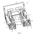
- edge seal module 1 is provided as part of a device for producing tubular bags and arranged in the conveying direction of the supplied tubular film approximately at the level of the filling tube.
- spreading elements which may be formed, for example, by spreading elements provided on the outside of the filling tube, as shown in FIG DE-A-42 03 798 are disclosed.
- expansion elements can also be used, as they are in DE-A-1 113 174 are described.
- the tubular film in the in Fig. 1 introduced edge seal module introduced.
- the spreading ends immediately before the edge seal module.
- a tubular bag with a rectangular cross-sectional area is formed from a film tube. Accordingly, the foil tube before insertion into the edge seal module 1 at its four edges in each case has a projecting tip. Associated with these four corners, jaws 2 assigned to the edge sealing module 1 are provided. The jaws 2 are respectively assigned counterhold, not shown. These counter-holders are provided directly opposite to the jaws 3 and form with them a gap in which the tip is guided and sealed. In other words, located between the opposing jaws 2 in the illustration according to Fig. 1 two counter-holders, not shown.
- the counter-holders are detachably arranged on the edge sealing module 1 and can be removed for maintenance and adjustment purposes.
- Fig. 1 is a position in which the device can be set up, for example, to guide a film tube over a filling tube which will be described in greater detail below.
- each hand wheels 7, 8 are provided at the end of the cross member 3, which cause the relative movement of the corresponding jaws 2a, 2c and 2b, 2d via spindles. In this movement is a movement of the respective jaws 2a, 2c and 2b, 2d in the direction of the longitudinal extension of the cross member 8.
- a handwheel 9 is provided, through which the jaws 8 can be moved perpendicular to the cross member. An actuation of the handwheel 9 accordingly changes the relative distance between the jaws 2a and 2b or 2c and 2d.
- Fig. 1 further discloses pneumatic cylinders 30 which respectively support the jaws 2a to 2d.
- the jaws can be moved to a rest position, ie be deducted in the longitudinal direction of the cross member 3 of the film material.
- the jaws 2 are floatingly mounted over the pneumatic cylinder 30.
- the cylinder 30 is not moved to feed the jaws 2 in an end position. Rather, the operating position of the jaws results from the fact that a state of equilibrium between the internal pressure in the pneumatic cylinder 30 and the resultant pressure force of the pneumatic cylinder 30 and a counterforce results, resulting from the pressure of an air cushion between the film material and the jaw, which presses against the cheek 2.
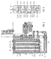
- Fig. 2 is a longitudinal sectional view through one of the jaws 2 shown.
- the jaws 2 are essentially formed by a block 10 of a CuCrZr3 alloy and have on their film-near surface 11 a plurality of this surface 11 passing through air outlet openings 12.
- There are two parallel rows of air outlet openings 12 are provided in the longitudinal direction, respectively offset in the vertical direction are formed to each other.
- the air outlet openings 12 communicate with an air distribution channel 13, which communicates with a meandering formed in the block 10 supply system 14 in connection.
- the recessed in the block 10 holes are in the side view according to Fig. 3 to recognize.
- this supply system 14 To the air outlet openings 12 guided air is in this supply system 14 is introduced there by the first transverse channel 14.1 deflected at the end to the second transverse duct 14.2, is guided at the end to the other side to the third transverse duct 14.3 and from there to the lying on the same side transverse duct 14.4, etc.
- the transverse ducts 14.1 to 14.13 are in the block 10 three holes for heating cartridges 15 and two holes 16 recessed for thermocouples.
- the air outlet near heater cartridge 15.1 and the corresponding thermocouple 16.1 are controlled by a separate control circuit; the other two heating cartridges 15.2, 15.3 are controlled by a separate control circuit due to the actual information of the second thermocouple 16.2.
- the heating cartridges 15 cause a heating of the block 10, so that it heats the film material of the opposite face arranged by its foil near surface 11 by heat radiation.
- the guided through the supply system 14 air through the warm block 10 is heated. Accordingly, cold air is usually introduced into the block 10.
- the thermocouples 16.1 and 16.2 allow accurate temperature control both to control the amount of heat transferred by heat radiation as well as the introduced by convection in the film material when sealing the edge heat content.
- the perforated strip 18 is provided offset from the film-near surface 11 of the block 12 a little backwards.
- a filling tube 23 is shown which is surrounded by the film tube 24 which is closed in the circumferential direction. As can be seen, protrudes from the side walls 25 of the film tube 24, a double-layered tip 26. At each of the edges 27 of the rectangular filling tube 23 and thus of the rectangular film tube 24 is such a tip 26.
- the ears 26 are guided in a gap 28 formed between the respective jaw 2a-2d and the associated counter-holder 21 a-21 d is.
- the anvils 21 are like the filling tube 23 attached directly to a common machine frame.
- the edge sealing module 1 is first set with the hand wheels 7, 8 and 9 to the desired tubular pouch format.
- the individual jaws 2 a-d with their corresponding cross members 3 can be delivered to the film tube 24.
- the device for producing the tubular bag is approached.
- the two cross members 3 are fed towards each other, so that the multi-layered tabs 26 in the gap 28, which is formed between the jaw 2 and the associated counter-holder 21, pass through.
- the air supply to the anvil 21 and the jaws 2 and the cooling device 17 is also switched on.
- the corners 26 are thereby compressed between a both sides of the tip 26 formed in the gap 28 air cushion.
- the tops 26 are heated by heat radiation and convection.
- the amount of heat introduced over the run length of the film material along the film-near surface 1 is determined such that the film material melts sufficiently in the region of the tip, so that the two layers of the film material are welded together.
- This welding is done without contact alone on the supplied air and due to the air pressure of the air cushion, which presses the film layers against each other. Accordingly, solid friction between the film and the edge sealing module 1 is prevented.
- the film runs smoothly through the edge seal module 1. After welding, the weld is rapidly cooled by the associated cooling device 17. At the end of the edge seal module 1, the edge seal has sufficient strength so that the two layers of the sealed edge 27 are firmly joined together.
- the two cartridges 15.2 and 15.3 are permanently switched on and keep the block to temperature, even if it is in the rest position.
- the film near heating cartridge 15.1 is switched on. Since at the same time the air supply is switched on, it is prevented that unnecessary heat energy during setting or in a fault condition of the machine, in which the cross member 3 are in the rest position, is discharged. Furthermore, excessive heating in the vicinity of the film material to be processed into a tubular bag is avoided.
- the device according to the invention can accordingly be used to save energy. Furthermore, only the edge is heated in a deliberately targeted manner, and further heating of the entire installation area of the device for producing the tubular bag is avoided.
- Subordinate to the edge seal module 1 is a transverse welding device for welding off the film tube, for example to produce a block bottom on the foil bag.
- the present invention is not limited to the shown embodiment.
- other non-ferrous alloys can be used to make the block 10.
- an alloy should be used which transmits a sufficient amount of heat via thermal radiation to the film material, even at relatively low temperatures.
Landscapes
- Engineering & Computer Science (AREA)
- Mechanical Engineering (AREA)
- Physics & Mathematics (AREA)
- Thermal Sciences (AREA)
- Fluid Mechanics (AREA)
- Chemical & Material Sciences (AREA)
- Combustion & Propulsion (AREA)
- Making Paper Articles (AREA)
- Containers And Plastic Fillers For Packaging (AREA)
- Lining Or Joining Of Plastics Or The Like (AREA)
Claims (23)
- Procédé de fabrication d'un sachet tubulaire, dans lequel un ruban de feuille est replié et le ruban de feuille replié est scellé par un dispositif de scellement longitudinal en un tube de feuille (24) dont le matériau en feuille est écarté dans la zone des arêtes (27) du sachet tubulaire à fabriquer et posé et scellé en plusieurs couches l'une contre l'autre,
caractérisé par le fait que
le matériau en feuille est déplacé lors du scellement des arêtes (27). - Procédé selon la revendication 1, caractérisé par le fait que les couches du matériau en feuille (26) sont poussées sans contact l'une contre l'autre lors du scellement des arêtes (27).
- Procédé selon la revendication 1 ou 2, caractérisé par le fait que le matériau en feuille est guidé lors du scellement d'une arête (27) à travers une fente (28) entre des mâchoires opposées (2, 21) et est tenu à distance des mâchoires (2) par l'intermédiaire d'un coussin de gaz.
- Procédé selon la revendication 3, caractérisé par le fait que le coussin de gaz est formé par du gaz chauffé.
- Procédé selon la revendication 3 ou 4, caractérisé par le fait que la largeur de fente est réglée automatiquement lors du fonctionnement.
- Procédé selon la revendication 5, caractérisé par le fait que la largeur de fente est réglée automatiquement sur la base d'un équilibre des forces entre la force de pression agissant sur les feuilles et une force de poussée exercée par un cylindre pneumatique.
- Procédé selon l'une des revendications précédentes, caractérisé par le fait que, pour le scellement d'une arête (27), le matériau en feuille est chauffé par rayonnement thermique et par convection de telle sorte que les couches du matériau en feuille (26) sont soudées ensemble.
- Procédé selon la revendication 7, caractérisé par le fait que la proportion de chaleur apportée par rayonnement thermique est comprise entre 30 % et 70 %.
- Procédé selon l'une des revendications précédentes, caractérisé par le fait que le matériau en feuille est chauffé par convection par de l'air qui est guidé dans des canaux (14.1 à 14.13) prévus dans la mâchoire (2), qu'une zone de mâchoire (11) proche de la feuille est tempérée séparément d'une zone de mâchoire (11) située plus profondément, et que la zone de mâchoire proche de la feuille n'est pas chauffée dans une position de repos dans laquelle la mâchoire (2) est tenue à distance du matériau en feuille.
- Procédé selon la revendication 9, caractérisé par le fait que les mâchoires (2) sont déplacées automatiquement dans la position de repos lorsqu'une immobilisation du matériau en feuille est détectée dans la zone de la mâchoire (2).
- Procédé selon l'une des revendications précédentes, caractérisé par le fait que l'amenée de gaz est arrêtée automatiquement lorsqu'une immobilisation du matériau en feuille est détectée dans la zone de la mâchoire (2).
- Procédé selon l'une des revendications précédentes, caractérisé par le fait que le matériau en feuille dans la zone d'une arête respective (27) est guidé entre l'une des mâchoires (2) et un appui complémentaire (21) qui soumet le matériau en feuille à un gaz chaud dont la température est inférieure à la température de scellement du matériau en feuille.
- Dispositif pour la fabrication de sachets tubulaires avec un épaulement formé pour le repliement d'un ruban de feuille, comprenant un dispositif de scellement longitudinal pour la fabrication d'un tube de feuille (24) à partir du ruban de feuille replié, avec un tuyau de remplissage (23) entouré par le tube de feuille (24), un dispositif de scellement transversal pour la production d'un sachet tubulaire comportant au moins une soudure transversale, un dispositif de séparation pour la séparation du matériau en feuille dans la zone de la soudure transversale, des éléments d'écartement pour l'écartement des arêtes du tube de feuille (24), des moyens de poussée pour pousser contre le matériau en feuille (26) en plusieurs couches dans la zone des arêtes écartées (27) et un dispositif de scellement d'arête (1) pour sceller le matériau en feuille à plusieurs couches,
caractérisé par le fait que
les moyens de poussée (2, 21) appuient sans le toucher sur le matériau en feuille à plusieurs couches ainsi poussées l'une contre l'autre. - Dispositif selon la revendication 13, caractérisé par le fait que les moyens de poussée (2, 21) comportent des buses de sortie de gaz (12, 22) qui sont orientées de telle sorte par rapport aux arêtes que du gaz sortant des orifices de sortie de gaz (12, 22) forme un coussin d'air poussant des deux côtés l'une contre l'autre les couches du matériau en feuille (26) dans la zone des arêtes (27).
- Dispositif selon la revendication 13 ou 14, caractérisé par le fait que les orifices de sortie de gaz (12) et les canaux (14.1 à 14.13) conduisant aux orifices de sortie de gaz (12) sont tempérés.
- Dispositif selon l'une des revendications 13 à 15, caractérisé par deux mâchoires (2, 21) opposées l'une à l'autre par rapport à chaque arête, munies d'orifices de sortie d'air (12, 22) et déplaçables l'une par rapport à l'autre.
- Dispositif selon l'une des revendications 13 à 16, caractérisé par le fait que, parmi les orifices de sortie de gaz (12, 22) opposés les uns aux autres, il est prévu un ensemble d'orifices de sortie de gaz (12) sur une mâchoire (2) qui comporte des canaux (14.1 à 14.13) faisant des méandres pour aller jusqu'aux orifices de sortie de gaz (12) et qui est traversée par au moins deux éléments de chauffage (15.1 ; 15.2 ; 15.3) ayant chacun un circuit de régulation associé.
- Dispositif selon la revendication 17, caractérisé par le fait que, en tout cas, l'élément de chauffage (15.1) proche des orifices de sortie de gaz (12) est régulé de telle sorte que cet élément de chauffage (15.1) est activé en fonction d'un signal qui représente le rapprochement des mâchoires associées (2, 21).
- Dispositif selon l'une des revendications 13 à 18, caractérisé par le fait qu'il est prévu à chaque fois en face d'une mâchoire (2) un appui complémentaire (21) qui comporte des buses de sortie de gaz (22) et que, pour tempérer l'air soufflé des buses de sortie d'air de l'ensemble des appuis complémentaires (21), il est simplement prévu un échangeur de chaleur central.
- Dispositif selon l'une des revendications 13 à 19, caractérisé par le fait que, la zone de la mâchoire (2) qui comporte les orifices de sortie de gaz (12) est en un alliage cuivre - chrome - zirconium.
- Dispositif selon l'une des revendications 13 à 20, caractérisé par un dispositif de refroidissement (17) placé en aval du dispositif de scellement d'arête (1) dans la direction de transport du matériau en feuille et comportant des orifices de sortie d'air (19) opposés pour chaque arête.
- Dispositif selon l'une des revendications 13 à 21, caractérisé par le fait que au moins l'une des mâchoires (2) prévues par paire pour chaque arête (27) est déplaçable par l'intermédiaire d'un cylindre pneumatique (30) et que cette mâchoire (2) est maintenue lors du fonctionnement dans une position de fonctionnement qui résulte de l'équilibre de la force de pression résultant contre le matériau en feuille du côté de la mâchoire (2) et de la force de pression agissant dans le cylindre pneumatique.
- Dispositif selon l'une des revendications 13 à 22, caractérisé par le fait que la largeur de la fente (28) résultant entre deux mâchoires (2, 21) opposées correspond lors du fonctionnement à une à trois fois l'épaisseur du matériau en feuille (26) se trouvant en plusieurs couches dans la zone de l'arête (27).
Priority Applications (4)
| Application Number | Priority Date | Filing Date | Title |
|---|---|---|---|
| DE502006002732T DE502006002732D1 (de) | 2006-11-17 | 2006-11-17 | Verfahren und Vorrichtung zum Herstellen eines Schlauchbeutels |
| EP06023956A EP1923202B1 (fr) | 2006-11-17 | 2006-11-17 | Procédé et dispositif pour produire un sac tubulaire |
| ES06023956T ES2320167T3 (es) | 2006-11-17 | 2006-11-17 | Procedimiento y dispositivo para la produccion de un saco tubular. |
| PT06023956T PT1923202E (pt) | 2006-11-17 | 2006-11-17 | Processo e dispositivo para a produção de um saco tubular |
Applications Claiming Priority (1)
| Application Number | Priority Date | Filing Date | Title |
|---|---|---|---|
| EP06023956A EP1923202B1 (fr) | 2006-11-17 | 2006-11-17 | Procédé et dispositif pour produire un sac tubulaire |
Publications (2)
| Publication Number | Publication Date |
|---|---|
| EP1923202A1 EP1923202A1 (fr) | 2008-05-21 |
| EP1923202B1 true EP1923202B1 (fr) | 2009-01-21 |
Family
ID=37909849
Family Applications (1)
| Application Number | Title | Priority Date | Filing Date |
|---|---|---|---|
| EP06023956A Not-in-force EP1923202B1 (fr) | 2006-11-17 | 2006-11-17 | Procédé et dispositif pour produire un sac tubulaire |
Country Status (4)
| Country | Link |
|---|---|
| EP (1) | EP1923202B1 (fr) |
| DE (1) | DE502006002732D1 (fr) |
| ES (1) | ES2320167T3 (fr) |
| PT (1) | PT1923202E (fr) |
Families Citing this family (4)
| Publication number | Priority date | Publication date | Assignee | Title |
|---|---|---|---|---|
| DE202011002178U1 (de) | 2011-02-01 | 2012-05-03 | Teepack Spezialmaschinen Gmbh & Co. Kg | Verpackungseinheit |
| DE102013105549B3 (de) * | 2013-05-29 | 2014-07-03 | Windmöller & Hölscher Kg | Kühlvorrichtung für die Kühlung einer Schweißnaht an einer Seitenfalte eines Folienmaterials in einer Sackfüllanlage |
| DE102014214593A1 (de) * | 2014-07-24 | 2016-01-28 | Windmöller & Hölscher Kg | Heißluftsiegeleinrichtung und Verfahren zum Heißluftsiegeln von kunststoffhaltiger Verpackung |
| WO2018206424A1 (fr) * | 2017-05-10 | 2018-11-15 | Gea Food Solutions Weert B.V. | Moyen de chauffage amélioré pour une enveloppeuse en continu |
Family Cites Families (4)
| Publication number | Priority date | Publication date | Assignee | Title |
|---|---|---|---|---|
| DE1461907A1 (de) * | 1964-08-20 | 1969-02-06 | Holstein & Kappert Maschf | Verfahren zur kontinuierlichen Herstellung von rechteckfoermigen Schlaeuchen und zur Durchfuehrung dieser Verfahren geeignete Vorrichtungen |
| DE4203798C2 (de) * | 1992-02-10 | 1999-07-15 | Rovema Gmbh | Verfahren und Vorrichtung zur Herstellung eines Schlauchbeutels |
| ITVE940014A1 (it) * | 1994-03-10 | 1995-09-10 | Pavan Mapimpianti Spa | Procedimento di saldatura di pellicola plastica per realizzare confezioni per prodotti alimentari ed apparecchiatura per effettutare |
| GB0020840D0 (en) * | 2000-08-23 | 2000-10-11 | Molins Plc | Heat sealing apparatus for packaging machinery |
-
2006
- 2006-11-17 EP EP06023956A patent/EP1923202B1/fr not_active Not-in-force
- 2006-11-17 DE DE502006002732T patent/DE502006002732D1/de active Active
- 2006-11-17 ES ES06023956T patent/ES2320167T3/es active Active
- 2006-11-17 PT PT06023956T patent/PT1923202E/pt unknown
Also Published As
| Publication number | Publication date |
|---|---|
| DE502006002732D1 (de) | 2009-03-12 |
| ES2320167T3 (es) | 2009-05-19 |
| EP1923202A1 (fr) | 2008-05-21 |
| PT1923202E (pt) | 2009-02-13 |
Similar Documents
| Publication | Publication Date | Title |
|---|---|---|
| EP3212381B1 (fr) | Dispositif et procede pour produire des sachets en plastique | |
| EP0498764B1 (fr) | Appareil pour la fabrication de corps tubulaires | |
| EP0212232A2 (fr) | Procédé et appareil pour la fabrication continue de feuilles thermoplastiques | |
| DE1779266A1 (de) | Verfahren und Anlage zur Bildung einer Seitenlaengsnaht an einem rohrfoermigen Koerper,der aus einem geschichteten Bahnmaterial besteht | |
| DE3019935C2 (fr) | ||
| WO2013083834A1 (fr) | Machine d'emballage pourvue d'un outil combiné de formage et de scellement | |
| DE102012015160B4 (de) | Vorrichtung und Verfahren zur Herstellung von Kunststoffbeuteln | |
| DE10213422B4 (de) | Vorrichtung zur Erzeugung mehrerer sich längs erstreckender Schweißkanten in einem Schlauchbeutelmaterial | |
| EP2681033B1 (fr) | Procédé et dispositif pour fabriquer des sacs dont les parois contiennent une matière polyoléfinique étirée | |
| DE2405943A1 (de) | Vorrichtung zum versiegeln von schweissbaren materialien | |
| DE69719686T2 (de) | Schneidvorrichtung in einer Form-Füll-Siegelmaschine | |
| EP0240827A1 (fr) | Dispositif de fabrication de sacs d'expédition avec des matelas d'air isolants | |
| EP3888893B1 (fr) | Procédé et dispositif de fabrication de sacs | |
| DE69731280T2 (de) | Versiegelungsvorrichtung | |
| EP1923202A1 (fr) | Procédé et dispositif pour produire un sac tubulaire | |
| EP2502727B1 (fr) | Poinçon inférieur amélioré pour bandes de feuilles épaisses | |
| EP2460642A1 (fr) | Dispositifs et procédés de fabrication d'une bande ondulée à matrice thermodurcissable renforcée par des fibres ainsi qu'une structure nid d'abeille thermodurcissable | |
| DE102015122560B4 (de) | Längstrennschweißvorrichtung für eine Folienverpackungsmaschine, Folienverpackungsmaschine und Verfahren | |
| CH695937A5 (de) | Verfahren und Vorrichtung zur Herstellung von aus schweissbaren Kunststoff-Folien durch Längsnahtschweissen gebildeter Rohrkörper. | |
| DE60113545T2 (de) | Vorrichtung und verfahren zum durchtrennen und versiegeln von kunststofffolien | |
| DE68920804T2 (de) | Verfahren zum Herstellen von Blasenverpackungen. | |
| DE102004049376B4 (de) | Verfahren zum Erzeugen einer Schweißkraft | |
| CH680350A5 (en) | Mfr. of packaging tubes from synthetic film - has film folded round mandrel and adjusted to size during longitudinal welding by air cushion between tube and mandrel | |
| DE10104002B4 (de) | Verfahren zum Temperieren zu verklebender Kunststofffolien sowie Vorrichtung zum Verkleben von Kunstfolie mit temperaturgesteuerter Transportwalze | |
| DE60201516T2 (de) | Verfahren und vorrichtung zur herstellung von behälterstreifen |
Legal Events
| Date | Code | Title | Description |
|---|---|---|---|
| PUAI | Public reference made under article 153(3) epc to a published international application that has entered the european phase |
Free format text: ORIGINAL CODE: 0009012 |
|
| 17P | Request for examination filed |
Effective date: 20070710 |
|
| AK | Designated contracting states |
Kind code of ref document: A1 Designated state(s): AT BE BG CH CY CZ DE DK EE ES FI FR GB GR HU IE IS IT LI LT LU LV MC NL PL PT RO SE SI SK TR |
|
| AX | Request for extension of the european patent |
Extension state: AL BA HR MK RS |
|
| GRAP | Despatch of communication of intention to grant a patent |
Free format text: ORIGINAL CODE: EPIDOSNIGR1 |
|
| GRAS | Grant fee paid |
Free format text: ORIGINAL CODE: EPIDOSNIGR3 |
|
| GRAA | (expected) grant |
Free format text: ORIGINAL CODE: 0009210 |
|
| AK | Designated contracting states |
Kind code of ref document: B1 Designated state(s): BE CZ DE ES FR GB IT LU NL PT |
|
| REG | Reference to a national code |
Ref country code: GB Ref legal event code: FG4D Free format text: NOT ENGLISH |
|
| AKX | Designation fees paid |
Designated state(s): BE CZ DE ES FR GB IT LU NL PT |
|
| REG | Reference to a national code |
Ref country code: PT Ref legal event code: SC4A Free format text: AVAILABILITY OF NATIONAL TRANSLATION Effective date: 20090203 |
|
| REF | Corresponds to: |
Ref document number: 502006002732 Country of ref document: DE Date of ref document: 20090312 Kind code of ref document: P |
|
| REG | Reference to a national code |
Ref country code: ES Ref legal event code: FG2A Ref document number: 2320167 Country of ref document: ES Kind code of ref document: T3 |
|
| PLBE | No opposition filed within time limit |
Free format text: ORIGINAL CODE: 0009261 |
|
| STAA | Information on the status of an ep patent application or granted ep patent |
Free format text: STATUS: NO OPPOSITION FILED WITHIN TIME LIMIT |
|
| 26N | No opposition filed |
Effective date: 20091022 |
|
| REG | Reference to a national code |
Ref country code: FR Ref legal event code: PLFP Year of fee payment: 10 |
|
| REG | Reference to a national code |
Ref country code: FR Ref legal event code: PLFP Year of fee payment: 11 |
|
| PGFP | Annual fee paid to national office [announced via postgrant information from national office to epo] |
Ref country code: GB Payment date: 20161128 Year of fee payment: 11 Ref country code: NL Payment date: 20161124 Year of fee payment: 11 Ref country code: FR Payment date: 20161127 Year of fee payment: 11 Ref country code: LU Payment date: 20161125 Year of fee payment: 11 Ref country code: DE Payment date: 20161125 Year of fee payment: 11 Ref country code: CZ Payment date: 20161102 Year of fee payment: 11 |
|
| PGFP | Annual fee paid to national office [announced via postgrant information from national office to epo] |
Ref country code: PT Payment date: 20161024 Year of fee payment: 11 Ref country code: ES Payment date: 20161123 Year of fee payment: 11 Ref country code: IT Payment date: 20161130 Year of fee payment: 11 Ref country code: BE Payment date: 20161124 Year of fee payment: 11 |
|
| REG | Reference to a national code |
Ref country code: DE Ref legal event code: R119 Ref document number: 502006002732 Country of ref document: DE |
|
| REG | Reference to a national code |
Ref country code: NL Ref legal event code: MM Effective date: 20171201 |
|
| GBPC | Gb: european patent ceased through non-payment of renewal fee |
Effective date: 20171117 |
|
| PG25 | Lapsed in a contracting state [announced via postgrant information from national office to epo] |
Ref country code: PT Free format text: LAPSE BECAUSE OF NON-PAYMENT OF DUE FEES Effective date: 20180517 Ref country code: CZ Free format text: LAPSE BECAUSE OF NON-PAYMENT OF DUE FEES Effective date: 20171117 |
|
| PG25 | Lapsed in a contracting state [announced via postgrant information from national office to epo] |
Ref country code: LU Free format text: LAPSE BECAUSE OF NON-PAYMENT OF DUE FEES Effective date: 20171117 |
|
| REG | Reference to a national code |
Ref country code: FR Ref legal event code: ST Effective date: 20180731 Ref country code: BE Ref legal event code: MM Effective date: 20171130 |
|
| PG25 | Lapsed in a contracting state [announced via postgrant information from national office to epo] |
Ref country code: DE Free format text: LAPSE BECAUSE OF NON-PAYMENT OF DUE FEES Effective date: 20180602 Ref country code: FR Free format text: LAPSE BECAUSE OF NON-PAYMENT OF DUE FEES Effective date: 20171130 Ref country code: IT Free format text: LAPSE BECAUSE OF NON-PAYMENT OF DUE FEES Effective date: 20171117 Ref country code: NL Free format text: LAPSE BECAUSE OF NON-PAYMENT OF DUE FEES Effective date: 20171201 |
|
| PG25 | Lapsed in a contracting state [announced via postgrant information from national office to epo] |
Ref country code: BE Free format text: LAPSE BECAUSE OF NON-PAYMENT OF DUE FEES Effective date: 20171130 Ref country code: GB Free format text: LAPSE BECAUSE OF NON-PAYMENT OF DUE FEES Effective date: 20171117 |
|
| PG25 | Lapsed in a contracting state [announced via postgrant information from national office to epo] |
Ref country code: ES Free format text: LAPSE BECAUSE OF NON-PAYMENT OF DUE FEES Effective date: 20171118 |