EP1923598A1 - Couche hydraulique dotée d'une membrane en forme d'ondes - Google Patents
Couche hydraulique dotée d'une membrane en forme d'ondes Download PDFInfo
- Publication number
- EP1923598A1 EP1923598A1 EP07020106A EP07020106A EP1923598A1 EP 1923598 A1 EP1923598 A1 EP 1923598A1 EP 07020106 A EP07020106 A EP 07020106A EP 07020106 A EP07020106 A EP 07020106A EP 1923598 A1 EP1923598 A1 EP 1923598A1
- Authority
- EP
- European Patent Office
- Prior art keywords
- membrane
- mount according
- hydraulic mount
- fluid
- hydraulic
- Prior art date
- Legal status (The legal status is an assumption and is not a legal conclusion. Google has not performed a legal analysis and makes no representation as to the accuracy of the status listed.)
- Granted
Links
- 239000012528 membrane Substances 0.000 title claims description 94
- 239000012530 fluid Substances 0.000 claims abstract description 17
- 239000011324 bead Substances 0.000 claims description 16
- 229920001971 elastomer Polymers 0.000 claims description 6
- 239000000806 elastomer Substances 0.000 claims description 3
- 238000005192 partition Methods 0.000 abstract 5
- 210000004379 membrane Anatomy 0.000 description 87
- 238000013016 damping Methods 0.000 description 11
- 230000015572 biosynthetic process Effects 0.000 description 5
- 238000002485 combustion reaction Methods 0.000 description 3
- 230000005284 excitation Effects 0.000 description 3
- 238000011161 development Methods 0.000 description 2
- 230000018109 developmental process Effects 0.000 description 2
- 239000000463 material Substances 0.000 description 2
- 238000001746 injection moulding Methods 0.000 description 1
- 238000004519 manufacturing process Methods 0.000 description 1
- 230000035515 penetration Effects 0.000 description 1
- 239000000126 substance Substances 0.000 description 1
Images
Classifications
-
- F—MECHANICAL ENGINEERING; LIGHTING; HEATING; WEAPONS; BLASTING
- F16—ENGINEERING ELEMENTS AND UNITS; GENERAL MEASURES FOR PRODUCING AND MAINTAINING EFFECTIVE FUNCTIONING OF MACHINES OR INSTALLATIONS; THERMAL INSULATION IN GENERAL
- F16F—SPRINGS; SHOCK-ABSORBERS; MEANS FOR DAMPING VIBRATION
- F16F13/00—Units comprising springs of the non-fluid type as well as vibration-dampers, shock-absorbers, or fluid springs
- F16F13/04—Units comprising springs of the non-fluid type as well as vibration-dampers, shock-absorbers, or fluid springs comprising both a plastics spring and a damper, e.g. a friction damper
- F16F13/06—Units comprising springs of the non-fluid type as well as vibration-dampers, shock-absorbers, or fluid springs comprising both a plastics spring and a damper, e.g. a friction damper the damper being a fluid damper, e.g. the plastics spring not forming a part of the wall of the fluid chamber of the damper
- F16F13/08—Units comprising springs of the non-fluid type as well as vibration-dampers, shock-absorbers, or fluid springs comprising both a plastics spring and a damper, e.g. a friction damper the damper being a fluid damper, e.g. the plastics spring not forming a part of the wall of the fluid chamber of the damper the plastics spring forming at least a part of the wall of the fluid chamber of the damper
- F16F13/10—Units comprising springs of the non-fluid type as well as vibration-dampers, shock-absorbers, or fluid springs comprising both a plastics spring and a damper, e.g. a friction damper the damper being a fluid damper, e.g. the plastics spring not forming a part of the wall of the fluid chamber of the damper the plastics spring forming at least a part of the wall of the fluid chamber of the damper the wall being at least in part formed by a flexible membrane or the like
- F16F13/105—Units comprising springs of the non-fluid type as well as vibration-dampers, shock-absorbers, or fluid springs comprising both a plastics spring and a damper, e.g. a friction damper the damper being a fluid damper, e.g. the plastics spring not forming a part of the wall of the fluid chamber of the damper the plastics spring forming at least a part of the wall of the fluid chamber of the damper the wall being at least in part formed by a flexible membrane or the like characterised by features of partitions between two working chambers
- F16F13/106—Design of constituent elastomeric parts, e.g. decoupling valve elements, or of immediate abutments therefor, e.g. cages
Definitions
- the invention relates to a hydraulic bearing, comprising two discs, a membrane and a fluid, wherein the membrane is positioned between the discs and wherein the membrane surface kraftbeaufschlagbar by the fluid and the membrane is thereby at least partially movable or deflected.
- Hydraulic bearings find particular use in motor vehicles, which are operated with internal combustion engines. They serve to dampen vibrations of the internal combustion engine. The vibrations of the internal combustion engine should be decoupled from the body of the motor vehicle. Usually, hydraulic bearings damp vibrations in the range between 5 and 15 Hz and isolate vibrations above 15 Hz.
- membranes in hydraulic bearings are either freely movable or fixedly arranged between two nozzle disks.
- An optimized hydraulic bearing shows a low dynamic Stiffness of the membrane, wherein the membrane further causes a high damping of road-excited vibrations.
- the invention is therefore based on the object, a hydraulic bearing of the type mentioned in such a way and further, that the membrane has a low dynamic stiffness and causes a high damping of road-excited vibrations.
- a hydraulic bearing of the type mentioned above is characterized in that the membrane comprises means which at least partially redirect the force such that the membrane is at least partially pressure thrust loaded.
- the generic type hydraulic bearings are structurally less suitable for use.
- the disadvantages of the generic hydromounts are due to the structure of the membrane.
- the membrane must exhibit a high degree of compliance with substantially orthogonal force applied to the surface of the membrane by a fluid.
- the membrane must be characterized by a low dynamic stiffness.
- this can be achieved by the provision of means which provide a substantially orthogonal force deflected in the membrane body such that the membrane body is subjected to pressure thrust. As a result, a large part of the force is absorbed within the membrane body and the vibration energy is converted into the deformation energy of the membrane.
- a pressure-loadable membrane can easily be deflected and deformed.
- a membrane is given which has a low dynamic stiffness due to their easy deformability.
- a membrane of this type allows a high damping of road-excited vibrations. Consequently, the object mentioned above is achieved.
- the means could be formed as beads, which are formed out of the membrane.
- the beads could be made of the same material and integral with the membrane. This specific embodiment allows a trouble-free production of the membrane, since this injection molding is produced in a mold. Furthermore, the formation of beads, which have elevations and depressions, allows a concertina deformability of the membrane. This deformability is favored by the fact that the beads adjoin one another and form angles with one another. If a force is now exerted on the membrane surface in the orthogonal direction, parts of the force components are diverted into the beads and the membrane is subjected to compressive thrust.
- the beads are arranged at right angles to one another in cross section.
- the formation of a right angle allows a particularly effective splitting of an orthogonal force in two force components, which are derived in the membrane body.
- the membrane could be circular and the means arranged concentrically.
- This concrete embodiment allows a positioning in a cylindrical designed hydraulic bearing.
- the concentric arrangement ensures that the membrane is uniformly deformable over its entire surface or over the entire membrane body.
- the membrane could be wave-shaped in cross-section and have a wave-shaped surface. It is concretely conceivable that the wave troughs and wave crests are generated by the elevations and depressions of the previously described beads. The wave-shaped configuration causes a problem-free deformability of the membrane in the clamped state.
- the membrane could be circular and have an edge region which is clamped between the discs.
- the formation of a border area allows the determination, namely the pinching of the membrane between two panes.
- Nozzle disks have recesses through which the fluid can pass and contact the membrane surface. Through the passing fluid, the membrane surface is acted upon with force and moves or moves them.
- the membrane could have a passage at its center.
- the formation of a passage allows the determination of the membrane in its center, namely when a flange is inserted through the passage.
- the passage may allow the passage of the fluid through the membrane without deflecting the membrane in the region of the passageway and providing a cushioning function. By dimensioning the passage, the damping effect or the dynamic stiffness of the membrane is adjustable.
- the passage is assigned an edge area.
- the formation of an edge region in the center allows the clamping of the membrane in its center.
- the dynamic stiffness and the damping behavior of the membrane can be additionally influenced, since in this way an annular Mambran is created, which is fixed at its outer periphery and inner circumference. This annular membrane could be fluid-tight.
- the membrane could be made of an elastomer. Against this background, it is quite conceivable that the membrane is made of rubber. Rubber shows a high chemical resistance to the fluids used in hydraulic bearings.
- a bead could extend over 1.5 mm in cross-section and the membrane could have a thickness of 2.5 mm at a diameter of 62 mm.
- This specific embodiment has proven to be particularly advantageous when the membrane is excited to vibrate with an excitation amplitude of 0.2 mm. Surprisingly, in this specific dimensioning, a very high loss angle occurs at an excitation amplitude of 0.2 mm. Surprisingly, at an excitation amplitude of 0.1 mm, a low dynamic stiffness is exhibited when the membrane has the dimensioning described here.
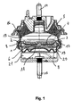
- Fig. 1 shows a hydraulic bearing, which has two discs 1 and 2, between which a membrane 3 is clamped.
- the discs 1 and 2 are designed as nozzle discs with recesses, which allow the passage of the fluid 4 through the nozzle discs on the membrane surface 5.
- the membrane surface 5 can be acted upon by the fluid 4 with force. By this application of force, the membrane 3 is at least partially deflected from its rest position or moved as a whole.
- the membrane 3 has means 6, which redirect the force at least partially such that the membrane 3 is at least partially loaded by passage.
- the hydraulic bearing of FIG. 1 is used to separate vibrations of an engine from the body.
- two attachment devices 14 and 15 are associated with the hydraulic bearing, which can be fixed to the body or on the engine of a motor vehicle.
- the hydraulic bearing further comprises an elastomeric body 16, which allows a relative movement of the fastening means 14 and 15 to each other when vibrations occur.
- the hydraulic bearing also has a damping channel 17, through which the fluid 4 can pass.
- the damping channel 17 is formed between the nozzle disks 1 and 2. From a first chamber 18, the fluid 4 can enter through the damping channel 17 into a second chamber 19, which is separated by a membrane 20 from a third chamber 21.
- the membrane 20 is deformed upon penetration of fluid 4 from the first chamber 18 and also causes a damping.
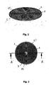
- Fig. 2 shows the membrane 3, which is positioned in the hydraulic bearing according to FIG. 1 between the nozzle disks 1 and 2.
- the means 6 are formed as beads 7.
- the beads 7 are formed out of the membrane and formed with this material uniformly and in one piece.
- the membrane 3 is formed annularly, wherein the means 6 and the beads 7 are arranged concentrically.
- the membrane 3 is wave-shaped in cross-section and has a wave-shaped surface 5.
- the membrane 3 shows a top view of the membrane 3.
- the membrane 3 has a passage 10 in its center 9. Through this passage 10 fluids can pass. Furthermore, the passage 10 can accommodate a fastening device which clamps the membrane 3 in its center 9.
- the membrane 3 is made of an elastomer, namely rubber.
- the membrane 3 according to FIG. 1 and FIG. 2 has an edge region 8, which is clamped between the panes 1, 2. When clamping the membrane 3 between the discs 1, 2, the membrane 3 is compressed in its thickness by 1/10 mm.
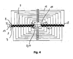
- FIG. 4 shows in a cross-sectional view the membrane 3 according to FIGS. 1 to 3.
- FIG. 4 shows the membrane 3 in a cross-sectional view along the line AA according to FIG. 3.
- FIG. 4 shows the membrane 3, which has an edge region 8 has, which can be clamped between the nozzle disks 1, 2.
- FIG. 4 shows that a passage 10 is arranged in the center 9 of the membrane 3. From Fig. 4 can also be seen that the beads 7 are arranged at right angles to each other in cross section. A bead 7 extends over 1.5 mm in cross section.
- the membrane 3 has a diameter 12 of 62 mm and a thickness of 2.5 mm.
- the passage 10 is associated with an edge region 11.
- This edge region 11 can be clamped in a fastening device or a flange.
- the membrane 3 is clamped both in the edge region 8 and at the edge region 11 between two panes 1, 2. It is also apparent from FIG. 4 that the membrane 3 is wave-shaped in cross-section and has a wave-shaped surface 5.
Landscapes
- Engineering & Computer Science (AREA)
- General Engineering & Computer Science (AREA)
- Mechanical Engineering (AREA)
- Combined Devices Of Dampers And Springs (AREA)
- Other Liquid Machine Or Engine Such As Wave Power Use (AREA)
Applications Claiming Priority (1)
| Application Number | Priority Date | Filing Date | Title |
|---|---|---|---|
| DE102006054110A DE102006054110A1 (de) | 2006-11-15 | 2006-11-15 | Hydrolager mit einer wellenförmigen Membran |
Publications (2)
| Publication Number | Publication Date |
|---|---|
| EP1923598A1 true EP1923598A1 (fr) | 2008-05-21 |
| EP1923598B1 EP1923598B1 (fr) | 2011-07-20 |
Family
ID=39016272
Family Applications (1)
| Application Number | Title | Priority Date | Filing Date |
|---|---|---|---|
| EP07020106A Revoked EP1923598B1 (fr) | 2006-11-15 | 2007-10-15 | Couche hydraulique dotée d'une membrane en forme d'ondes |
Country Status (3)
| Country | Link |
|---|---|
| EP (1) | EP1923598B1 (fr) |
| AT (1) | ATE517274T1 (fr) |
| DE (1) | DE102006054110A1 (fr) |
Cited By (4)
| Publication number | Priority date | Publication date | Assignee | Title |
|---|---|---|---|---|
| EP2428698A3 (fr) * | 2010-09-14 | 2014-09-17 | Carl Freudenberg KG | Paroi de séparation pour une couche hydraulique |
| JP2017141960A (ja) * | 2010-10-22 | 2017-08-17 | クーパー−スタンダード・オートモーティブ・インコーポレーテッド | 低ノイズのデカップラ |
| EP2420699A4 (fr) * | 2009-04-13 | 2017-10-25 | Toyo Tire & Rubber Co., Ltd. | Dispositif anti-vibration scellé de façon étanche vis-à-vis des liquides |
| US11428290B2 (en) | 2017-12-26 | 2022-08-30 | Prospira Corporation | Vibration isolating device |
Citations (6)
| Publication number | Priority date | Publication date | Assignee | Title |
|---|---|---|---|---|
| EP0072262A1 (fr) * | 1981-08-07 | 1983-02-16 | Automobiles Peugeot | Cale élastique, notamment pour la suspension d'un moteur de véhicule |
| EP0262296A1 (fr) * | 1986-09-26 | 1988-04-06 | Boge A.G. | Support en caoutchouc à amortissement hydraulique |
| US4742999A (en) * | 1986-05-16 | 1988-05-10 | Flower Wallace C | Quiet acting fluid filled vibration isolator having predictable low level high frequency minimum dynamic stiffness |
| EP0331951A2 (fr) * | 1988-03-09 | 1989-09-13 | Metzeler Gimetall Ag | Membrane de découplage pour support de moteur à plusieurs chambres et à amortissement hydraulique |
| DE4027826C1 (en) * | 1990-09-01 | 1991-07-18 | Mercedes-Benz Aktiengesellschaft, 7000 Stuttgart, De | Hydraulically damping engine mounting support - has amplitude limiting diaphragm, hydraulically in series with overflow passage |
| DE4233240A1 (de) * | 1991-10-04 | 1993-04-08 | Toyoda Gosei Kk | Hydraulische daempfervorrichtung |
Family Cites Families (2)
| Publication number | Priority date | Publication date | Assignee | Title |
|---|---|---|---|---|
| DE19843558B4 (de) * | 1998-09-23 | 2004-07-22 | Zf Boge Elastmetall Gmbh | Hydraulisch dämpfendes Gummilager |
| DE10200592A1 (de) * | 2002-01-10 | 2003-07-31 | Freudenberg Carl Kg | Hydraulisch dämpfendes Lager |
-
2006
- 2006-11-15 DE DE102006054110A patent/DE102006054110A1/de not_active Withdrawn
-
2007
- 2007-10-15 EP EP07020106A patent/EP1923598B1/fr not_active Revoked
- 2007-10-15 AT AT07020106T patent/ATE517274T1/de active
Patent Citations (6)
| Publication number | Priority date | Publication date | Assignee | Title |
|---|---|---|---|---|
| EP0072262A1 (fr) * | 1981-08-07 | 1983-02-16 | Automobiles Peugeot | Cale élastique, notamment pour la suspension d'un moteur de véhicule |
| US4742999A (en) * | 1986-05-16 | 1988-05-10 | Flower Wallace C | Quiet acting fluid filled vibration isolator having predictable low level high frequency minimum dynamic stiffness |
| EP0262296A1 (fr) * | 1986-09-26 | 1988-04-06 | Boge A.G. | Support en caoutchouc à amortissement hydraulique |
| EP0331951A2 (fr) * | 1988-03-09 | 1989-09-13 | Metzeler Gimetall Ag | Membrane de découplage pour support de moteur à plusieurs chambres et à amortissement hydraulique |
| DE4027826C1 (en) * | 1990-09-01 | 1991-07-18 | Mercedes-Benz Aktiengesellschaft, 7000 Stuttgart, De | Hydraulically damping engine mounting support - has amplitude limiting diaphragm, hydraulically in series with overflow passage |
| DE4233240A1 (de) * | 1991-10-04 | 1993-04-08 | Toyoda Gosei Kk | Hydraulische daempfervorrichtung |
Cited By (4)
| Publication number | Priority date | Publication date | Assignee | Title |
|---|---|---|---|---|
| EP2420699A4 (fr) * | 2009-04-13 | 2017-10-25 | Toyo Tire & Rubber Co., Ltd. | Dispositif anti-vibration scellé de façon étanche vis-à-vis des liquides |
| EP2428698A3 (fr) * | 2010-09-14 | 2014-09-17 | Carl Freudenberg KG | Paroi de séparation pour une couche hydraulique |
| JP2017141960A (ja) * | 2010-10-22 | 2017-08-17 | クーパー−スタンダード・オートモーティブ・インコーポレーテッド | 低ノイズのデカップラ |
| US11428290B2 (en) | 2017-12-26 | 2022-08-30 | Prospira Corporation | Vibration isolating device |
Also Published As
| Publication number | Publication date |
|---|---|
| EP1923598B1 (fr) | 2011-07-20 |
| DE102006054110A1 (de) | 2008-05-21 |
| ATE517274T1 (de) | 2011-08-15 |
Similar Documents
| Publication | Publication Date | Title |
|---|---|---|
| DE2802896C2 (de) | Gummilager mit hydraulischer Dämpfung | |
| DE102016123428B4 (de) | Düsenplatteneinrichtung für Motorbefestigung | |
| DE2950109C2 (fr) | ||
| DE102007016399B4 (de) | Biaxial dämpfendes Hydrolager | |
| DE4111318A1 (de) | Hydraulische, buchsenfoermige daempfungsvorrichtung | |
| DE102004001322B4 (de) | Akustisch entkoppeltes Hydrolager | |
| EP0986489B1 (fr) | Dispositif de decouplage pour moteur electrique | |
| DE69618097T2 (de) | Gerät zur Schwingungsisolierung | |
| DE102015009161A1 (de) | Schwingungstilger | |
| EP1923598B1 (fr) | Couche hydraulique dotée d'une membrane en forme d'ondes | |
| DE2823720C2 (de) | Zweikammer-Motorlager mit hydraulischer Dämpfung, insbesondere für Kraftfahrzeuge | |
| EP2864625B1 (fr) | Support pour fixer un distributeur de carburant à un moteur à combustion interne et système d'injection de carburant comprenant un tel support | |
| DE102017112168B4 (de) | Trennvorrichtung zum Trennen einer Arbeitskammer und einer Ausgleichskammer eines hydraulisch dämpfenden Lagers sowie ein hydraulisch dämpfendes Lager | |
| EP0704640B1 (fr) | Support pour moteurs de véhicules automobiles | |
| EP2657504B1 (fr) | Système de support pour la fixation d'un composant sur un moteur à combustion interne | |
| WO2015197213A1 (fr) | Palier hydraulique et véhicule à moteur équipé d'un tel palier hydraulique | |
| WO2008000460A2 (fr) | Élément d'amortissement | |
| DE102012101396B3 (de) | Elastische Ankopplung einer einen Flansch aufweisenden Baueinheit, um einen passiven Schwingungstilger auszubilden | |
| DE4440392A1 (de) | Lager zur dämpfenden Anordnung schwingender Massen | |
| DE102007054882A1 (de) | Hydrolager | |
| WO2016074815A1 (fr) | Palier hydraulique et véhicule automobile équipé d'un tel palier hydraulique | |
| EP1670658B1 (fr) | Support pendulaire | |
| DE10222053B4 (de) | Dämpferventil | |
| EP3960591B1 (fr) | Pièce étanche | |
| DE102005048593B4 (de) | Kunststoffleitung, insbesondere hydraulische Kupplungsdruck-Übertragungsleitung für ein Kraftfahrzeug |
Legal Events
| Date | Code | Title | Description |
|---|---|---|---|
| PUAI | Public reference made under article 153(3) epc to a published international application that has entered the european phase |
Free format text: ORIGINAL CODE: 0009012 |
|
| AK | Designated contracting states |
Kind code of ref document: A1 Designated state(s): AT BE BG CH CY CZ DE DK EE ES FI FR GB GR HU IE IS IT LI LT LU LV MC MT NL PL PT RO SE SI SK TR |
|
| AX | Request for extension of the european patent |
Extension state: AL BA HR MK RS |
|
| AKX | Designation fees paid | ||
| 17P | Request for examination filed |
Effective date: 20081120 |
|
| RBV | Designated contracting states (corrected) |
Designated state(s): AT BE BG CH CY CZ DE DK EE ES FI FR GB GR HU IE IS IT LI LT LU LV MC MT NL PL PT RO SE SI SK TR |
|
| 17Q | First examination report despatched |
Effective date: 20100407 |
|
| GRAP | Despatch of communication of intention to grant a patent |
Free format text: ORIGINAL CODE: EPIDOSNIGR1 |
|
| RIN1 | Information on inventor provided before grant (corrected) |
Inventor name: FARRENKOPF, PETER Inventor name: BECKMANN, WOLFGANG Inventor name: HOLZ, ROLAND Inventor name: LOBMUELLER, GUENTHER Inventor name: BERNHARD, PETRA |
|
| GRAS | Grant fee paid |
Free format text: ORIGINAL CODE: EPIDOSNIGR3 |
|
| GRAA | (expected) grant |
Free format text: ORIGINAL CODE: 0009210 |
|
| AK | Designated contracting states |
Kind code of ref document: B1 Designated state(s): AT BE BG CH CY CZ DE DK EE ES FI FR GB GR HU IE IS IT LI LT LU LV MC MT NL PL PT RO SE SI SK TR |
|
| REG | Reference to a national code |
Ref country code: GB Ref legal event code: FG4D Free format text: NOT ENGLISH |
|
| REG | Reference to a national code |
Ref country code: CH Ref legal event code: EP |
|
| REG | Reference to a national code |
Ref country code: DE Ref legal event code: R096 Ref document number: 502007007695 Country of ref document: DE Effective date: 20110908 |
|
| REG | Reference to a national code |
Ref country code: NL Ref legal event code: VDEP Effective date: 20110720 |
|
| PG25 | Lapsed in a contracting state [announced via postgrant information from national office to epo] |
Ref country code: IS Free format text: LAPSE BECAUSE OF FAILURE TO SUBMIT A TRANSLATION OF THE DESCRIPTION OR TO PAY THE FEE WITHIN THE PRESCRIBED TIME-LIMIT Effective date: 20111120 Ref country code: FI Free format text: LAPSE BECAUSE OF FAILURE TO SUBMIT A TRANSLATION OF THE DESCRIPTION OR TO PAY THE FEE WITHIN THE PRESCRIBED TIME-LIMIT Effective date: 20110720 Ref country code: NL Free format text: LAPSE BECAUSE OF FAILURE TO SUBMIT A TRANSLATION OF THE DESCRIPTION OR TO PAY THE FEE WITHIN THE PRESCRIBED TIME-LIMIT Effective date: 20110720 Ref country code: LT Free format text: LAPSE BECAUSE OF FAILURE TO SUBMIT A TRANSLATION OF THE DESCRIPTION OR TO PAY THE FEE WITHIN THE PRESCRIBED TIME-LIMIT Effective date: 20110720 Ref country code: SE Free format text: LAPSE BECAUSE OF FAILURE TO SUBMIT A TRANSLATION OF THE DESCRIPTION OR TO PAY THE FEE WITHIN THE PRESCRIBED TIME-LIMIT Effective date: 20110720 Ref country code: PT Free format text: LAPSE BECAUSE OF FAILURE TO SUBMIT A TRANSLATION OF THE DESCRIPTION OR TO PAY THE FEE WITHIN THE PRESCRIBED TIME-LIMIT Effective date: 20111121 |
|
| REG | Reference to a national code |
Ref country code: IE Ref legal event code: FD4D |
|
| PG25 | Lapsed in a contracting state [announced via postgrant information from national office to epo] |
Ref country code: SI Free format text: LAPSE BECAUSE OF FAILURE TO SUBMIT A TRANSLATION OF THE DESCRIPTION OR TO PAY THE FEE WITHIN THE PRESCRIBED TIME-LIMIT Effective date: 20110720 Ref country code: PL Free format text: LAPSE BECAUSE OF FAILURE TO SUBMIT A TRANSLATION OF THE DESCRIPTION OR TO PAY THE FEE WITHIN THE PRESCRIBED TIME-LIMIT Effective date: 20110720 Ref country code: GR Free format text: LAPSE BECAUSE OF FAILURE TO SUBMIT A TRANSLATION OF THE DESCRIPTION OR TO PAY THE FEE WITHIN THE PRESCRIBED TIME-LIMIT Effective date: 20111021 Ref country code: CY Free format text: LAPSE BECAUSE OF FAILURE TO SUBMIT A TRANSLATION OF THE DESCRIPTION OR TO PAY THE FEE WITHIN THE PRESCRIBED TIME-LIMIT Effective date: 20110720 Ref country code: LV Free format text: LAPSE BECAUSE OF FAILURE TO SUBMIT A TRANSLATION OF THE DESCRIPTION OR TO PAY THE FEE WITHIN THE PRESCRIBED TIME-LIMIT Effective date: 20110720 |
|
| BERE | Be: lapsed |
Owner name: CARL FREUDENBERG K.G. Effective date: 20111031 |
|
| PG25 | Lapsed in a contracting state [announced via postgrant information from national office to epo] |
Ref country code: IE Free format text: LAPSE BECAUSE OF FAILURE TO SUBMIT A TRANSLATION OF THE DESCRIPTION OR TO PAY THE FEE WITHIN THE PRESCRIBED TIME-LIMIT Effective date: 20110720 Ref country code: SK Free format text: LAPSE BECAUSE OF FAILURE TO SUBMIT A TRANSLATION OF THE DESCRIPTION OR TO PAY THE FEE WITHIN THE PRESCRIBED TIME-LIMIT Effective date: 20110720 Ref country code: CZ Free format text: LAPSE BECAUSE OF FAILURE TO SUBMIT A TRANSLATION OF THE DESCRIPTION OR TO PAY THE FEE WITHIN THE PRESCRIBED TIME-LIMIT Effective date: 20110720 |
|
| PLBI | Opposition filed |
Free format text: ORIGINAL CODE: 0009260 |
|
| PLAX | Notice of opposition and request to file observation + time limit sent |
Free format text: ORIGINAL CODE: EPIDOSNOBS2 |
|
| PG25 | Lapsed in a contracting state [announced via postgrant information from national office to epo] |
Ref country code: RO Free format text: LAPSE BECAUSE OF FAILURE TO SUBMIT A TRANSLATION OF THE DESCRIPTION OR TO PAY THE FEE WITHIN THE PRESCRIBED TIME-LIMIT Effective date: 20110720 Ref country code: MC Free format text: LAPSE BECAUSE OF NON-PAYMENT OF DUE FEES Effective date: 20111031 Ref country code: EE Free format text: LAPSE BECAUSE OF FAILURE TO SUBMIT A TRANSLATION OF THE DESCRIPTION OR TO PAY THE FEE WITHIN THE PRESCRIBED TIME-LIMIT Effective date: 20110720 Ref country code: IT Free format text: LAPSE BECAUSE OF FAILURE TO SUBMIT A TRANSLATION OF THE DESCRIPTION OR TO PAY THE FEE WITHIN THE PRESCRIBED TIME-LIMIT Effective date: 20110720 |
|
| REG | Reference to a national code |
Ref country code: CH Ref legal event code: PL |
|
| 26 | Opposition filed |
Opponent name: ANVIS DEUTSCHLAND GMBH Effective date: 20120420 |
|
| PG25 | Lapsed in a contracting state [announced via postgrant information from national office to epo] |
Ref country code: DK Free format text: LAPSE BECAUSE OF FAILURE TO SUBMIT A TRANSLATION OF THE DESCRIPTION OR TO PAY THE FEE WITHIN THE PRESCRIBED TIME-LIMIT Effective date: 20110720 |
|
| PLBB | Reply of patent proprietor to notice(s) of opposition received |
Free format text: ORIGINAL CODE: EPIDOSNOBS3 |
|
| PG25 | Lapsed in a contracting state [announced via postgrant information from national office to epo] |
Ref country code: LI Free format text: LAPSE BECAUSE OF NON-PAYMENT OF DUE FEES Effective date: 20111031 Ref country code: BE Free format text: LAPSE BECAUSE OF NON-PAYMENT OF DUE FEES Effective date: 20111031 Ref country code: CH Free format text: LAPSE BECAUSE OF NON-PAYMENT OF DUE FEES Effective date: 20111031 |
|
| REG | Reference to a national code |
Ref country code: DE Ref legal event code: R026 Ref document number: 502007007695 Country of ref document: DE Effective date: 20120420 |
|
| PG25 | Lapsed in a contracting state [announced via postgrant information from national office to epo] |
Ref country code: MT Free format text: LAPSE BECAUSE OF FAILURE TO SUBMIT A TRANSLATION OF THE DESCRIPTION OR TO PAY THE FEE WITHIN THE PRESCRIBED TIME-LIMIT Effective date: 20110720 |
|
| PG25 | Lapsed in a contracting state [announced via postgrant information from national office to epo] |
Ref country code: ES Free format text: LAPSE BECAUSE OF FAILURE TO SUBMIT A TRANSLATION OF THE DESCRIPTION OR TO PAY THE FEE WITHIN THE PRESCRIBED TIME-LIMIT Effective date: 20111031 |
|
| PG25 | Lapsed in a contracting state [announced via postgrant information from national office to epo] |
Ref country code: LU Free format text: LAPSE BECAUSE OF NON-PAYMENT OF DUE FEES Effective date: 20111015 |
|
| PG25 | Lapsed in a contracting state [announced via postgrant information from national office to epo] |
Ref country code: BG Free format text: LAPSE BECAUSE OF FAILURE TO SUBMIT A TRANSLATION OF THE DESCRIPTION OR TO PAY THE FEE WITHIN THE PRESCRIBED TIME-LIMIT Effective date: 20111020 |
|
| PG25 | Lapsed in a contracting state [announced via postgrant information from national office to epo] |
Ref country code: TR Free format text: LAPSE BECAUSE OF FAILURE TO SUBMIT A TRANSLATION OF THE DESCRIPTION OR TO PAY THE FEE WITHIN THE PRESCRIBED TIME-LIMIT Effective date: 20110720 |
|
| PG25 | Lapsed in a contracting state [announced via postgrant information from national office to epo] |
Ref country code: HU Free format text: LAPSE BECAUSE OF FAILURE TO SUBMIT A TRANSLATION OF THE DESCRIPTION OR TO PAY THE FEE WITHIN THE PRESCRIBED TIME-LIMIT Effective date: 20110720 |
|
| REG | Reference to a national code |
Ref country code: AT Ref legal event code: MM01 Ref document number: 517274 Country of ref document: AT Kind code of ref document: T Effective date: 20121031 |
|
| PG25 | Lapsed in a contracting state [announced via postgrant information from national office to epo] |
Ref country code: AT Free format text: LAPSE BECAUSE OF NON-PAYMENT OF DUE FEES Effective date: 20121031 |
|
| PGFP | Annual fee paid to national office [announced via postgrant information from national office to epo] |
Ref country code: GB Payment date: 20131021 Year of fee payment: 7 Ref country code: FR Payment date: 20131021 Year of fee payment: 7 Ref country code: DE Payment date: 20131028 Year of fee payment: 7 |
|
| RDAF | Communication despatched that patent is revoked |
Free format text: ORIGINAL CODE: EPIDOSNREV1 |
|
| APBM | Appeal reference recorded |
Free format text: ORIGINAL CODE: EPIDOSNREFNO |
|
| APBP | Date of receipt of notice of appeal recorded |
Free format text: ORIGINAL CODE: EPIDOSNNOA2O |
|
| REG | Reference to a national code |
Ref country code: DE Ref legal event code: R103 Ref document number: 502007007695 Country of ref document: DE Ref country code: DE Ref legal event code: R064 Ref document number: 502007007695 Country of ref document: DE |
|
| APAH | Appeal reference modified |
Free format text: ORIGINAL CODE: EPIDOSCREFNO |
|
| APBU | Appeal procedure closed |
Free format text: ORIGINAL CODE: EPIDOSNNOA9O |
|
| RDAG | Patent revoked |
Free format text: ORIGINAL CODE: 0009271 |
|
| STAA | Information on the status of an ep patent application or granted ep patent |
Free format text: STATUS: PATENT REVOKED |
|
| 27W | Patent revoked |
Effective date: 20140721 |
|
| GBPR | Gb: patent revoked under art. 102 of the ep convention designating the uk as contracting state |
Effective date: 20140721 |
|
| REG | Reference to a national code |
Ref country code: DE Ref legal event code: R107 Ref document number: 502007007695 Country of ref document: DE Effective date: 20141030 |
|
| REG | Reference to a national code |
Ref country code: AT Ref legal event code: MA03 Ref document number: 517274 Country of ref document: AT Kind code of ref document: T Effective date: 20140721 |
|
| REG | Reference to a national code |
Ref country code: CH Ref legal event code: PK Free format text: DAS DATUM DES WIDERRUFS DURCH EPA IST NICHT KORREKT |