EP1923613A1 - Dispositif de soupape, en particulier pour usage agricole - Google Patents
Dispositif de soupape, en particulier pour usage agricole Download PDFInfo
- Publication number
- EP1923613A1 EP1923613A1 EP06425778A EP06425778A EP1923613A1 EP 1923613 A1 EP1923613 A1 EP 1923613A1 EP 06425778 A EP06425778 A EP 06425778A EP 06425778 A EP06425778 A EP 06425778A EP 1923613 A1 EP1923613 A1 EP 1923613A1
- Authority
- EP
- European Patent Office
- Prior art keywords
- blocking
- blocking lever
- valve
- lever
- valve chamber
- Prior art date
- Legal status (The legal status is an assumption and is not a legal conclusion. Google has not performed a legal analysis and makes no representation as to the accuracy of the status listed.)
- Granted
Links
- 230000000694 effects Effects 0.000 title claims abstract description 6
- 230000000903 blocking effect Effects 0.000 claims abstract description 62
- 239000012530 fluid Substances 0.000 claims abstract description 27
- 239000004009 herbicide Substances 0.000 claims abstract description 13
- YZHUMGUJCQRKBT-UHFFFAOYSA-M sodium chlorate Chemical compound [Na+].[O-]Cl(=O)=O YZHUMGUJCQRKBT-UHFFFAOYSA-M 0.000 claims abstract description 13
- 230000001747 exhibiting effect Effects 0.000 claims abstract description 3
- 210000000056 organ Anatomy 0.000 claims description 12
- 230000002452 interceptive effect Effects 0.000 claims description 4
- 239000012528 membrane Substances 0.000 description 10
- 238000012423 maintenance Methods 0.000 description 7
- 238000009333 weeding Methods 0.000 description 5
- 238000010586 diagram Methods 0.000 description 4
- 238000007689 inspection Methods 0.000 description 4
- 230000035508 accumulation Effects 0.000 description 3
- 238000009825 accumulation Methods 0.000 description 3
- 239000003638 chemical reducing agent Substances 0.000 description 2
- 239000011343 solid material Substances 0.000 description 2
- 230000003213 activating effect Effects 0.000 description 1
- 230000015556 catabolic process Effects 0.000 description 1
- 239000002131 composite material Substances 0.000 description 1
- 238000001514 detection method Methods 0.000 description 1
- 238000003973 irrigation Methods 0.000 description 1
- 230000002262 irrigation Effects 0.000 description 1
- 239000002245 particle Substances 0.000 description 1
- 239000007787 solid Substances 0.000 description 1
Images


Classifications
-
- F—MECHANICAL ENGINEERING; LIGHTING; HEATING; WEAPONS; BLASTING
- F16—ENGINEERING ELEMENTS AND UNITS; GENERAL MEASURES FOR PRODUCING AND MAINTAINING EFFECTIVE FUNCTIONING OF MACHINES OR INSTALLATIONS; THERMAL INSULATION IN GENERAL
- F16K—VALVES; TAPS; COCKS; ACTUATING-FLOATS; DEVICES FOR VENTING OR AERATING
- F16K31/00—Actuating devices; Operating means; Releasing devices
- F16K31/12—Actuating devices; Operating means; Releasing devices actuated by fluid
- F16K31/36—Actuating devices; Operating means; Releasing devices actuated by fluid in which fluid from the circuit is constantly supplied to the fluid motor
- F16K31/38—Actuating devices; Operating means; Releasing devices actuated by fluid in which fluid from the circuit is constantly supplied to the fluid motor in which the fluid works directly on both sides of the fluid motor, one side being connected by means of a restricted passage and the motor being actuated by operating a discharge from that side
- F16K31/385—Actuating devices; Operating means; Releasing devices actuated by fluid in which fluid from the circuit is constantly supplied to the fluid motor in which the fluid works directly on both sides of the fluid motor, one side being connected by means of a restricted passage and the motor being actuated by operating a discharge from that side the fluid acting on a diaphragm
Definitions
- the invention relates to a valve device, in particular for agricultural applications.
- the invention can be used in the agricultural sector, and in particular it is destined for agricultural activities related to safeguarding and weeding the crops.
- weeding operations are normally carried out using one or more manifolds which can be connected to a source supplying one or more weed-killing fluids.
- Each manifold is defined by a plurality of valve devices each having an outlet conduit, or delivery conduit, connectable to special irrigation/dispensing and/or draining systems.
- Each valve device exhibits a single-block body internally of which the conduits necessary for the functioning thereof are afforded.
- a valve is arranged internally of the single-block body, which valve can be commuted between a closed condition, in which the supplied fluid transits internally of a main conduit, and an open condition, in which the supplied fluid flows through the respective outlet and delivery conduit.
- each valve device Generally the commutation of the valve of each valve device is activated by means of a respective gear reducer, which operates in the single-block body.
- Each gear reducer or like activating organ is appropriately connected to an electrical supply via one or more electric cables.
- valve devices are subject to periodical and frequent breakdowns due to wear on the valves as well as to accumulations of solid particles internally of the conduits, requiring continual inspection and/or maintenance operations.
- valve devices are not accessible from outside and require the intervention of technical assistant even when the cause of malfunctioning depends on a problem of small entity, or on an accumulation of solid material internally of the conduits.
- the cause of malfunctioning in the above-mentioned devices can also depend on the absence of electrical supply due to a localised fault in the cabling or the electrical connectors.
- the impossibility of identifying the true cause of the malfunctioning leads to a need to call out specialised technical assistance.
- the technical aim at the basis of the present invention is to invent a valve device which is able to obviate the cited drawbacks.
- an important further aim of the invention is to provide a valve device which is easily accessible from outside in order to permit both inspection and if necessary intervention for maintenance or replacement of specific components.
- a further aim of the invention is to signal the presence or absence of the electrical supply required for commutation of the valve means operating internally of each valve device.
- the specified set technical aim and the other specified aims are attained by a valve device, in particular for agricultural weeding activities according to what is described in the accompanying claims.
- valve device of the invention A description of the valve device of the invention will now be made by way of non-limiting example.
- 1 denotes in its entirety a valve device, in particular for agricultural weeding applications, in agreement with the present invention.
- the device 1 comprises a body 2 exhibiting a first portion 2a and a second portion 2b which are reciprocally engaged in order to define a main conduit 3 which is connectable to a supply source (not shown) of one or more weedkilling fluids and an outlet conduit 4 for conveying the weedkiller fluid in transit in the main conduit 3 towards a dispenser conduit (not illustrated).
- the first portion 2a and the second portion 2b of the body 2 also define a valve body 5 interpositioned between the main conduit 3 and the outlet conduit 4.
- the valve body 5 contains a valve 6 commutable between a closed condition, in which a weedkiller fluid, transiting through the main conduit 3, does not flow through the outlet conduit 4, and an open configuration, in which the weedkiller fluid, transiting through the main conduit 3, flows through the outlet conduit 4.
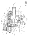
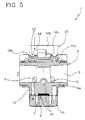
- valve 6 comprises at least a membrane 7 ( figures 4 and 5 ) which during operation is interpositioned between the main conduit 3 and the outlet conduit 4.
- the membrane 7 divides the valve chamber 5 into two chambers 8, 9, each in fluid communication with the main conduit 3.
- a first chamber 8 is directly in fluid communication with the main conduit 3, while a second chamber 9 is in fluid communication with the main conduit 3 by means of a connection conduit 10 (visible also in figure 5 ) which extends at least partially through the first portion 2a and at least partially through the second portion 2b.
- the weedkiller fluid in supply occupies both the first chamber 8 and the second chamber 9, acting on the membrane 7 of the valve 6 at a same pressure level.
- the membrane 7 surface exposed to the weedkiller fluid internally of the first chamber 8 exhibits a smaller area than the surface of the membrane 7 which is exposed to the weedkiller fluid occupying the inside of the second chamber 9 of the valve chamber 5. Consequently, with a same pressure and different surfaces, the membrane 7 is kept in the closed condition, i.e. it is held against an inlet mouth 4a of the outlet conduit 4 so that the weedkiller fluid transiting through the main conduit 3 is unable to flow through the outlet conduit 4.
- the second chamber 9 of the valve chamber 5 is advantageously in fluid communication with the outlet conduit 4 by means of a breather conduit 12 normally kept closed by a pilot valve 11.
- the pilot valve 11 is preferably controlled by an actuator organ 13, preferably of an electromagnetic type and operatively associable with the body 2 of the device 1, so that on switching on an electrical supply the pilot valve 11 opens the breather valve 12, enabling the weedkiller fluid present inside the second chamber 9 to reach the outlet chamber 4.
- the pilot valve 11 occludes the breather conduit 12, resetting the closed condition of the membrane 7 internally of the valve chamber 5.
- the actuator organ 13 is advantageously provided with at least a light emitter 14, preferably a LED, which displays and signals the presence or absence of an electrical supply. With the light emitter 14 it is therefore possible to check if the actuator organ 14 is correctly electrically supplied. Switching the light emitter 14 on or off therefore signals the correct functioning of the electrical supply or the presence of a fault in the cabling or the electrical supply connections.
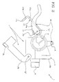
- first and second portions 2a, 2b of the body 2 are advantageously mobile with respect to one another between a closed position, in which the valve chamber 5 is sealedly closed ( figure 1 ) and an open position in which the valve chamber 5 is open and accessible from the outside ( figure 2 ).
- the second portion 2b of the body 2 is hinged to the first portion 2a, so that the second portion 2b is rotatable about a hinge axis X between the first and second positions.
- the device 1 further comprises means for blocking 15 which are operatively connected to the body 2 in order to keep the second portion 2b in the closed position.
- the means for blocking 15 preferably comprise a blocking lever 16 which are operatively engaged to the first portion 2a of the body 2 so as to be mobile between a blocking position ( figure 1 ), in which the blocking lever 15 adheres at least partially to the first portion 2a and acts on the second portion 2b to maintain the second portion 2b in the closed position, and an unblocking position ( figure 1 , shaped in a broken line) in which the blocking lever 16 does not adhere to the first portion 2a and the second portion 2b is free to move.
- a blocking position figure 1
- an unblocking position figure 1 , shaped in a broken line
- the blocking lever 16 is preferably hinged to the first portion 2a of the body 2 in order to rotate about a rotation axis Y which is substantially parallel to the hinge axis X and to the main conduit 3, between the blocking position and the unblocking position.
- the means for blocking further comprise a hook element 17 connected to the blocking lever 16 and engageable to the second portion 2b in order to keep the second portion 2b in the closed position when the blocking lever 16 is arranged in the blocking position.
- the hook element 17 is preferably hinged to the blocking lever 16 at the hinge point thereof to the first portion 2a of the body 2.
- the blocking lever 16 comprises a pair of arms 16a developing substantially parallel to one another, united by at least a crossbar 16b, preferably two in number.
- the blocking lever 16 comprises at least a hinge pin 16c, extending between the arms 16a on an opposite side with respect to the crossbars 16b.
- the hinge pin 16c engages in a respective hinge seating afforded in the first portion 2a in proximity of the main conduit 3.
- the hook element 17 exhibits a pair of arms 17a extending substantially parallel to one another, each being engaged to a respective arm 16a of the blocking lever 16 at the position of the hinge pin 16c.
- Each arm 17a of the hook element 17 exhibits, on the opposite side to the blocking lever 16, a terminal portion 17b which is engaged to the transversal terminal portion 17b of the other arm 17a by means of a hook crosspiece 17c.
- the means for blocking 15 advantageously comprise a safety catch 18 operatively engaged to the first portion 2a of the body 2 for holding the blocking lever 16 in the blocking position.
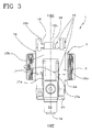
- the safety catch 18 is mobile between an interfering position ( figure 3 , continuous line), in which it holds the blocking lever 16 in the blocking position, and a disengaged position ( figure 3 , broken line), in which the blocking lever 16 is free to move.
- the safety catch 18 is preferably provided with at least an elastic recall element (not illustrated in the figures of the drawings) which is predisposed to bring the safety catch 18 into the interfering position.
- the above-mentioned hook element 17 is further predisposed to keep, between the arms 17a thereof, the actuator organ 13 engaged to the second portion 2b of the body 2 when the blocking lever 16 is arranged in the blocking position.
- the blocking lever 16 must be brought from the blocking position into the unblocking position in order to disengage the hook element 17 from the obturator organ 13 which can then be removed.
- valve device 1 of the present invention resolves the drawbacks encountered in the prior art and offers considerable advantages.
- the device of the present invention is easily accessible from the outside as it can be opened simply and rapidly. Consequently, parts and components particularly liable to wear, or to the accumulation of solid materials, such as for example the valves and the valve chamber, can be directly inspected, replaced and/or appropriately cleaned without there being the need for specialised technical assistance, which can be called only when the problems encountered in the malfunctioning device are of a different entity to the above-mentioned problems.
- the composite structure of the body of the device enables the operators in the sector immediately to reach the zones which are most subject to malfunctioning, and to intervene in case where the entity of the problem requires replacement and/or usual device maintenance.
- the opening and/or the closing of the body of the device can be performed simply by acting directly on the means for blocking, without there being any need for tools and/or special equipment.
- the device can be opened directly and manually by anybody.
- the means for blocking are advantageously also provided with a safety catch which keeps the blocking lever in the blocking position, preventing the lever from displacing accidentally into the unblocked position, such as for example after an impact with an agricultural vehicle.
- a light emitter associated to each actuator organ enables the operator to verify whether any eventual fault in the functioning of the above-mentioned devices are due to electrical supply faults, possibly due to connection or cabling problems, or whether the faults concern mechanical and/or structural problems in the valve devices.
Landscapes
- Engineering & Computer Science (AREA)
- General Engineering & Computer Science (AREA)
- Mechanical Engineering (AREA)
- Lift Valve (AREA)
- Catching Or Destruction (AREA)
- Valve Housings (AREA)
Priority Applications (3)
| Application Number | Priority Date | Filing Date | Title |
|---|---|---|---|
| EP06425778A EP1923613B1 (fr) | 2006-11-14 | 2006-11-14 | Dispositif de soupape, en particulier pour usage agricole |
| DE602006004762T DE602006004762D1 (de) | 2006-11-14 | 2006-11-14 | Ventilvorrichtung, insbesondere zur landwirtschaftlichen Verwendung |
| AT06425778T ATE420312T1 (de) | 2006-11-14 | 2006-11-14 | Ventilvorrichtung, insbesondere zur landwirtschaftlichen verwendung |
Applications Claiming Priority (1)
| Application Number | Priority Date | Filing Date | Title |
|---|---|---|---|
| EP06425778A EP1923613B1 (fr) | 2006-11-14 | 2006-11-14 | Dispositif de soupape, en particulier pour usage agricole |
Publications (2)
| Publication Number | Publication Date |
|---|---|
| EP1923613A1 true EP1923613A1 (fr) | 2008-05-21 |
| EP1923613B1 EP1923613B1 (fr) | 2009-01-07 |
Family
ID=37888332
Family Applications (1)
| Application Number | Title | Priority Date | Filing Date |
|---|---|---|---|
| EP06425778A Not-in-force EP1923613B1 (fr) | 2006-11-14 | 2006-11-14 | Dispositif de soupape, en particulier pour usage agricole |
Country Status (3)
| Country | Link |
|---|---|
| EP (1) | EP1923613B1 (fr) |
| AT (1) | ATE420312T1 (fr) |
| DE (1) | DE602006004762D1 (fr) |
Cited By (1)
| Publication number | Priority date | Publication date | Assignee | Title |
|---|---|---|---|---|
| CN106885030A (zh) * | 2017-04-26 | 2017-06-23 | 毛天明 | 一种有断电致动和自动复位功能的防火排烟阀电动执行器 |
Citations (7)
| Publication number | Priority date | Publication date | Assignee | Title |
|---|---|---|---|---|
| US2131271A (en) * | 1936-05-08 | 1938-09-27 | Skinner Irrigation Company | Irrigation device |
| US2149928A (en) * | 1938-07-12 | 1939-03-07 | Economy Faucet Co | Faucet |
| US2889849A (en) * | 1957-01-28 | 1959-06-09 | Shohan Elliot | Irrigation valve |
| US3424430A (en) * | 1966-10-31 | 1969-01-28 | Madeleine M Hoelsch | Swingably supported valve |
| GB1431695A (en) * | 1973-04-17 | 1976-04-14 | Kah C L C | Irrigation sprinkler system control employing pilot operated pressure actuated and sequenced valve assemblies |
| US3954251A (en) * | 1973-10-15 | 1976-05-04 | Whitey Research Tool Co. | Fluid system device |
| US4316480A (en) * | 1978-10-30 | 1982-02-23 | Kah Jr Carl L C | Sequencing valve |
-
2006
- 2006-11-14 EP EP06425778A patent/EP1923613B1/fr not_active Not-in-force
- 2006-11-14 AT AT06425778T patent/ATE420312T1/de not_active IP Right Cessation
- 2006-11-14 DE DE602006004762T patent/DE602006004762D1/de active Active
Patent Citations (7)
| Publication number | Priority date | Publication date | Assignee | Title |
|---|---|---|---|---|
| US2131271A (en) * | 1936-05-08 | 1938-09-27 | Skinner Irrigation Company | Irrigation device |
| US2149928A (en) * | 1938-07-12 | 1939-03-07 | Economy Faucet Co | Faucet |
| US2889849A (en) * | 1957-01-28 | 1959-06-09 | Shohan Elliot | Irrigation valve |
| US3424430A (en) * | 1966-10-31 | 1969-01-28 | Madeleine M Hoelsch | Swingably supported valve |
| GB1431695A (en) * | 1973-04-17 | 1976-04-14 | Kah C L C | Irrigation sprinkler system control employing pilot operated pressure actuated and sequenced valve assemblies |
| US3954251A (en) * | 1973-10-15 | 1976-05-04 | Whitey Research Tool Co. | Fluid system device |
| US4316480A (en) * | 1978-10-30 | 1982-02-23 | Kah Jr Carl L C | Sequencing valve |
Cited By (2)
| Publication number | Priority date | Publication date | Assignee | Title |
|---|---|---|---|---|
| CN106885030A (zh) * | 2017-04-26 | 2017-06-23 | 毛天明 | 一种有断电致动和自动复位功能的防火排烟阀电动执行器 |
| CN106885030B (zh) * | 2017-04-26 | 2022-12-30 | 毛天明 | 一种有断电致动和自动复位功能的防火排烟阀电动执行器 |
Also Published As
| Publication number | Publication date |
|---|---|
| EP1923613B1 (fr) | 2009-01-07 |
| DE602006004762D1 (de) | 2009-02-26 |
| ATE420312T1 (de) | 2009-01-15 |
Similar Documents
| Publication | Publication Date | Title |
|---|---|---|
| US20070267063A1 (en) | Unloader valve for pressurized fluid delivery system | |
| US7077153B2 (en) | Side control faucet with diverter assembly | |
| JP3280003B2 (ja) | 電磁弁集合体用給排気装置 | |
| US6205599B1 (en) | Covered eyewash fountain | |
| KR20130009777A (ko) | 밸브 시스템 | |
| US20090301590A1 (en) | Fuel shutoff slide valve | |
| CN1474902A (zh) | 用于真空马桶的冲洗流体阀 | |
| US11092257B2 (en) | Serviceable valve carousel system | |
| US7004199B1 (en) | Fluid control apparatus | |
| EP1923613B1 (fr) | Dispositif de soupape, en particulier pour usage agricole | |
| CN107743459B (zh) | 用于机动车的阀和清洁装置 | |
| US7147002B2 (en) | Modular multi-function fluid flow control device | |
| US5934327A (en) | Valve for cryogenic fluid | |
| EP2700826B1 (fr) | Circuit hydraulique pour vérin | |
| CN107206533B (zh) | 用于供给冷却剂的设备、用于这种设备的控制系统和用于操作这种冷却剂供给系统的方法 | |
| CA2801053A1 (fr) | Dispositif de commande pour le guidage d'un fluide | |
| DK2511579T3 (en) | fluid valve | |
| CN1474903A (zh) | 用于真空马桶的阀组 | |
| WO2023118838A1 (fr) | Raccord | |
| US6490963B2 (en) | Hydraulic line coupling arrangement | |
| JP3505028B2 (ja) | 色替バルブ装置 | |
| KR102489675B1 (ko) | 유압 밸브 및 농업용 트랙터 프론트 로더의 유압 제어장치 | |
| KR102534933B1 (ko) | 유압 밸브 및 농업용 트랙터 프론트 로더의 유압 제어장치 | |
| EP4299956A1 (fr) | Électrovanne pour distribuer un fluide et kit de pièces de rechange associé | |
| CN1399067A (zh) | 发动机燃料的输送装置 |
Legal Events
| Date | Code | Title | Description |
|---|---|---|---|
| PUAI | Public reference made under article 153(3) epc to a published international application that has entered the european phase |
Free format text: ORIGINAL CODE: 0009012 |
|
| 17P | Request for examination filed |
Effective date: 20070705 |
|
| AK | Designated contracting states |
Kind code of ref document: A1 Designated state(s): AT BE BG CH CY CZ DE DK EE ES FI FR GB GR HU IE IS IT LI LT LU LV MC NL PL PT RO SE SI SK TR |
|
| AX | Request for extension of the european patent |
Extension state: AL BA HR MK RS |
|
| GRAP | Despatch of communication of intention to grant a patent |
Free format text: ORIGINAL CODE: EPIDOSNIGR1 |
|
| GRAS | Grant fee paid |
Free format text: ORIGINAL CODE: EPIDOSNIGR3 |
|
| GRAA | (expected) grant |
Free format text: ORIGINAL CODE: 0009210 |
|
| AK | Designated contracting states |
Kind code of ref document: B1 Designated state(s): AT BE BG CH CY CZ DE DK EE ES FI FR GB GR HU IE IS IT LI LT LU LV MC NL PL PT RO SE SI SK TR |
|
| REG | Reference to a national code |
Ref country code: GB Ref legal event code: FG4D |
|
| REG | Reference to a national code |
Ref country code: CH Ref legal event code: EP |
|
| AKX | Designation fees paid |
Designated state(s): AT BE BG CH CY CZ DE DK EE ES FI FR GB GR HU IE IS IT LI LT LU LV MC NL PL PT RO SE SI SK TR |
|
| REG | Reference to a national code |
Ref country code: IE Ref legal event code: FG4D |
|
| REF | Corresponds to: |
Ref document number: 602006004762 Country of ref document: DE Date of ref document: 20090226 Kind code of ref document: P |
|
| PG25 | Lapsed in a contracting state [announced via postgrant information from national office to epo] |
Ref country code: NL Free format text: LAPSE BECAUSE OF FAILURE TO SUBMIT A TRANSLATION OF THE DESCRIPTION OR TO PAY THE FEE WITHIN THE PRESCRIBED TIME-LIMIT Effective date: 20090107 Ref country code: SI Free format text: LAPSE BECAUSE OF FAILURE TO SUBMIT A TRANSLATION OF THE DESCRIPTION OR TO PAY THE FEE WITHIN THE PRESCRIBED TIME-LIMIT Effective date: 20090107 |
|
| NLV1 | Nl: lapsed or annulled due to failure to fulfill the requirements of art. 29p and 29m of the patents act | ||
| PG25 | Lapsed in a contracting state [announced via postgrant information from national office to epo] |
Ref country code: LT Free format text: LAPSE BECAUSE OF FAILURE TO SUBMIT A TRANSLATION OF THE DESCRIPTION OR TO PAY THE FEE WITHIN THE PRESCRIBED TIME-LIMIT Effective date: 20090107 Ref country code: FI Free format text: LAPSE BECAUSE OF FAILURE TO SUBMIT A TRANSLATION OF THE DESCRIPTION OR TO PAY THE FEE WITHIN THE PRESCRIBED TIME-LIMIT Effective date: 20090107 Ref country code: ES Free format text: LAPSE BECAUSE OF FAILURE TO SUBMIT A TRANSLATION OF THE DESCRIPTION OR TO PAY THE FEE WITHIN THE PRESCRIBED TIME-LIMIT Effective date: 20090418 |
|
| PG25 | Lapsed in a contracting state [announced via postgrant information from national office to epo] |
Ref country code: PL Free format text: LAPSE BECAUSE OF FAILURE TO SUBMIT A TRANSLATION OF THE DESCRIPTION OR TO PAY THE FEE WITHIN THE PRESCRIBED TIME-LIMIT Effective date: 20090107 Ref country code: SE Free format text: LAPSE BECAUSE OF FAILURE TO SUBMIT A TRANSLATION OF THE DESCRIPTION OR TO PAY THE FEE WITHIN THE PRESCRIBED TIME-LIMIT Effective date: 20090407 Ref country code: LV Free format text: LAPSE BECAUSE OF FAILURE TO SUBMIT A TRANSLATION OF THE DESCRIPTION OR TO PAY THE FEE WITHIN THE PRESCRIBED TIME-LIMIT Effective date: 20090107 Ref country code: PT Free format text: LAPSE BECAUSE OF FAILURE TO SUBMIT A TRANSLATION OF THE DESCRIPTION OR TO PAY THE FEE WITHIN THE PRESCRIBED TIME-LIMIT Effective date: 20090608 Ref country code: AT Free format text: LAPSE BECAUSE OF FAILURE TO SUBMIT A TRANSLATION OF THE DESCRIPTION OR TO PAY THE FEE WITHIN THE PRESCRIBED TIME-LIMIT Effective date: 20090107 Ref country code: IS Free format text: LAPSE BECAUSE OF FAILURE TO SUBMIT A TRANSLATION OF THE DESCRIPTION OR TO PAY THE FEE WITHIN THE PRESCRIBED TIME-LIMIT Effective date: 20090507 |
|
| PG25 | Lapsed in a contracting state [announced via postgrant information from national office to epo] |
Ref country code: BE Free format text: LAPSE BECAUSE OF FAILURE TO SUBMIT A TRANSLATION OF THE DESCRIPTION OR TO PAY THE FEE WITHIN THE PRESCRIBED TIME-LIMIT Effective date: 20090107 |
|
| PG25 | Lapsed in a contracting state [announced via postgrant information from national office to epo] |
Ref country code: DK Free format text: LAPSE BECAUSE OF FAILURE TO SUBMIT A TRANSLATION OF THE DESCRIPTION OR TO PAY THE FEE WITHIN THE PRESCRIBED TIME-LIMIT Effective date: 20090107 Ref country code: EE Free format text: LAPSE BECAUSE OF FAILURE TO SUBMIT A TRANSLATION OF THE DESCRIPTION OR TO PAY THE FEE WITHIN THE PRESCRIBED TIME-LIMIT Effective date: 20090107 Ref country code: CZ Free format text: LAPSE BECAUSE OF FAILURE TO SUBMIT A TRANSLATION OF THE DESCRIPTION OR TO PAY THE FEE WITHIN THE PRESCRIBED TIME-LIMIT Effective date: 20090107 |
|
| PLBE | No opposition filed within time limit |
Free format text: ORIGINAL CODE: 0009261 |
|
| STAA | Information on the status of an ep patent application or granted ep patent |
Free format text: STATUS: NO OPPOSITION FILED WITHIN TIME LIMIT |
|
| PG25 | Lapsed in a contracting state [announced via postgrant information from national office to epo] |
Ref country code: RO Free format text: LAPSE BECAUSE OF FAILURE TO SUBMIT A TRANSLATION OF THE DESCRIPTION OR TO PAY THE FEE WITHIN THE PRESCRIBED TIME-LIMIT Effective date: 20090107 Ref country code: SK Free format text: LAPSE BECAUSE OF FAILURE TO SUBMIT A TRANSLATION OF THE DESCRIPTION OR TO PAY THE FEE WITHIN THE PRESCRIBED TIME-LIMIT Effective date: 20090107 |
|
| 26N | No opposition filed |
Effective date: 20091008 |
|
| PG25 | Lapsed in a contracting state [announced via postgrant information from national office to epo] |
Ref country code: BG Free format text: LAPSE BECAUSE OF FAILURE TO SUBMIT A TRANSLATION OF THE DESCRIPTION OR TO PAY THE FEE WITHIN THE PRESCRIBED TIME-LIMIT Effective date: 20090407 |
|
| PG25 | Lapsed in a contracting state [announced via postgrant information from national office to epo] |
Ref country code: MC Free format text: LAPSE BECAUSE OF NON-PAYMENT OF DUE FEES Effective date: 20091130 |
|
| REG | Reference to a national code |
Ref country code: IE Ref legal event code: MM4A |
|
| PG25 | Lapsed in a contracting state [announced via postgrant information from national office to epo] |
Ref country code: GR Free format text: LAPSE BECAUSE OF FAILURE TO SUBMIT A TRANSLATION OF THE DESCRIPTION OR TO PAY THE FEE WITHIN THE PRESCRIBED TIME-LIMIT Effective date: 20090408 Ref country code: IE Free format text: LAPSE BECAUSE OF NON-PAYMENT OF DUE FEES Effective date: 20091114 |
|
| PG25 | Lapsed in a contracting state [announced via postgrant information from national office to epo] |
Ref country code: LU Free format text: LAPSE BECAUSE OF NON-PAYMENT OF DUE FEES Effective date: 20091114 |
|
| PG25 | Lapsed in a contracting state [announced via postgrant information from national office to epo] |
Ref country code: HU Free format text: LAPSE BECAUSE OF FAILURE TO SUBMIT A TRANSLATION OF THE DESCRIPTION OR TO PAY THE FEE WITHIN THE PRESCRIBED TIME-LIMIT Effective date: 20090708 |
|
| REG | Reference to a national code |
Ref country code: CH Ref legal event code: PL |
|
| GBPC | Gb: european patent ceased through non-payment of renewal fee |
Effective date: 20101114 |
|
| PG25 | Lapsed in a contracting state [announced via postgrant information from national office to epo] |
Ref country code: CH Free format text: LAPSE BECAUSE OF NON-PAYMENT OF DUE FEES Effective date: 20101130 Ref country code: LI Free format text: LAPSE BECAUSE OF NON-PAYMENT OF DUE FEES Effective date: 20101130 |
|
| PG25 | Lapsed in a contracting state [announced via postgrant information from national office to epo] |
Ref country code: TR Free format text: LAPSE BECAUSE OF FAILURE TO SUBMIT A TRANSLATION OF THE DESCRIPTION OR TO PAY THE FEE WITHIN THE PRESCRIBED TIME-LIMIT Effective date: 20090107 |
|
| PG25 | Lapsed in a contracting state [announced via postgrant information from national office to epo] |
Ref country code: CY Free format text: LAPSE BECAUSE OF FAILURE TO SUBMIT A TRANSLATION OF THE DESCRIPTION OR TO PAY THE FEE WITHIN THE PRESCRIBED TIME-LIMIT Effective date: 20090107 |
|
| PG25 | Lapsed in a contracting state [announced via postgrant information from national office to epo] |
Ref country code: GB Free format text: LAPSE BECAUSE OF NON-PAYMENT OF DUE FEES Effective date: 20101114 |
|
| PGFP | Annual fee paid to national office [announced via postgrant information from national office to epo] |
Ref country code: FR Payment date: 20131129 Year of fee payment: 8 Ref country code: IT Payment date: 20131028 Year of fee payment: 8 |
|
| PGFP | Annual fee paid to national office [announced via postgrant information from national office to epo] |
Ref country code: DE Payment date: 20140131 Year of fee payment: 8 |
|
| REG | Reference to a national code |
Ref country code: DE Ref legal event code: R119 Ref document number: 602006004762 Country of ref document: DE |
|
| REG | Reference to a national code |
Ref country code: FR Ref legal event code: ST Effective date: 20150731 |
|
| PG25 | Lapsed in a contracting state [announced via postgrant information from national office to epo] |
Ref country code: DE Free format text: LAPSE BECAUSE OF NON-PAYMENT OF DUE FEES Effective date: 20150602 |
|
| PG25 | Lapsed in a contracting state [announced via postgrant information from national office to epo] |
Ref country code: FR Free format text: LAPSE BECAUSE OF NON-PAYMENT OF DUE FEES Effective date: 20141201 |
|
| PG25 | Lapsed in a contracting state [announced via postgrant information from national office to epo] |
Ref country code: IT Free format text: LAPSE BECAUSE OF NON-PAYMENT OF DUE FEES Effective date: 20141114 |