EP1923706A2 - Dispositif de détection de carte - Google Patents
Dispositif de détection de carte Download PDFInfo
- Publication number
- EP1923706A2 EP1923706A2 EP08075035A EP08075035A EP1923706A2 EP 1923706 A2 EP1923706 A2 EP 1923706A2 EP 08075035 A EP08075035 A EP 08075035A EP 08075035 A EP08075035 A EP 08075035A EP 1923706 A2 EP1923706 A2 EP 1923706A2
- Authority
- EP
- European Patent Office
- Prior art keywords
- card
- carousel
- cards
- station
- actuator
- Prior art date
- Legal status (The legal status is an assumption and is not a legal conclusion. Google has not performed a legal analysis and makes no representation as to the accuracy of the status listed.)
- Withdrawn
Links
- 238000001514 detection method Methods 0.000 title claims abstract description 17
- 230000003287 optical effect Effects 0.000 claims abstract description 49
- 230000033001 locomotion Effects 0.000 claims abstract description 13
- 230000001960 triggered effect Effects 0.000 claims abstract 4
- 230000037361 pathway Effects 0.000 claims description 4
- 238000012545 processing Methods 0.000 claims description 4
- 238000012360 testing method Methods 0.000 description 127
- 239000003570 air Substances 0.000 description 121
- 239000000523 sample Substances 0.000 description 83
- 238000011534 incubation Methods 0.000 description 76
- 238000009826 distribution Methods 0.000 description 39
- 230000012010 growth Effects 0.000 description 23
- 239000012472 biological sample Substances 0.000 description 20
- 230000007246 mechanism Effects 0.000 description 15
- 238000000926 separation method Methods 0.000 description 15
- 238000012546 transfer Methods 0.000 description 14
- 239000003153 chemical reaction reagent Substances 0.000 description 13
- 238000007865 diluting Methods 0.000 description 13
- 239000012530 fluid Substances 0.000 description 13
- 244000005700 microbiome Species 0.000 description 13
- 238000002834 transmittance Methods 0.000 description 12
- 238000013461 design Methods 0.000 description 10
- 238000006243 chemical reaction Methods 0.000 description 8
- 239000003795 chemical substances by application Substances 0.000 description 8
- 238000005520 cutting process Methods 0.000 description 8
- 230000002906 microbiologic effect Effects 0.000 description 8
- 238000000034 method Methods 0.000 description 7
- 239000001963 growth medium Substances 0.000 description 6
- 238000003780 insertion Methods 0.000 description 6
- 230000037431 insertion Effects 0.000 description 6
- QVGXLLKOCUKJST-UHFFFAOYSA-N atomic oxygen Chemical compound [O] QVGXLLKOCUKJST-UHFFFAOYSA-N 0.000 description 5
- 239000003085 diluting agent Substances 0.000 description 5
- 238000005259 measurement Methods 0.000 description 5
- 229910052760 oxygen Inorganic materials 0.000 description 5
- 239000001301 oxygen Substances 0.000 description 5
- 230000002411 adverse Effects 0.000 description 4
- 238000004458 analytical method Methods 0.000 description 4
- 239000003242 anti bacterial agent Substances 0.000 description 4
- 229940088710 antibiotic agent Drugs 0.000 description 4
- 230000008859 change Effects 0.000 description 4
- 238000004891 communication Methods 0.000 description 4
- 230000006870 function Effects 0.000 description 4
- 230000006872 improvement Effects 0.000 description 4
- 238000012423 maintenance Methods 0.000 description 3
- 230000008569 process Effects 0.000 description 3
- 239000011800 void material Substances 0.000 description 3
- 108020004711 Nucleic Acid Probes Proteins 0.000 description 2
- 230000009471 action Effects 0.000 description 2
- 239000012080 ambient air Substances 0.000 description 2
- 230000003115 biocidal effect Effects 0.000 description 2
- 239000003124 biologic agent Substances 0.000 description 2
- 239000013060 biological fluid Substances 0.000 description 2
- 230000005540 biological transmission Effects 0.000 description 2
- 238000004140 cleaning Methods 0.000 description 2
- 238000010276 construction Methods 0.000 description 2
- 238000010586 diagram Methods 0.000 description 2
- 238000001506 fluorescence spectroscopy Methods 0.000 description 2
- 238000004519 manufacturing process Methods 0.000 description 2
- 239000000463 material Substances 0.000 description 2
- 239000002853 nucleic acid probe Substances 0.000 description 2
- 230000002093 peripheral effect Effects 0.000 description 2
- 230000001737 promoting effect Effects 0.000 description 2
- 230000003014 reinforcing effect Effects 0.000 description 2
- 241000894006 Bacteria Species 0.000 description 1
- 240000008100 Brassica rapa Species 0.000 description 1
- 241000237509 Patinopecten sp. Species 0.000 description 1
- FAPWRFPIFSIZLT-UHFFFAOYSA-M Sodium chloride Chemical compound [Na+].[Cl-] FAPWRFPIFSIZLT-UHFFFAOYSA-M 0.000 description 1
- 238000003556 assay Methods 0.000 description 1
- 230000000712 assembly Effects 0.000 description 1
- 238000000429 assembly Methods 0.000 description 1
- 230000001419 dependent effect Effects 0.000 description 1
- 238000009792 diffusion process Methods 0.000 description 1
- 201000010099 disease Diseases 0.000 description 1
- 208000037265 diseases, disorders, signs and symptoms Diseases 0.000 description 1
- 229940079593 drug Drugs 0.000 description 1
- 239000003814 drug Substances 0.000 description 1
- 239000000428 dust Substances 0.000 description 1
- 230000000694 effects Effects 0.000 description 1
- 235000013305 food Nutrition 0.000 description 1
- 238000013095 identification testing Methods 0.000 description 1
- 238000010348 incorporation Methods 0.000 description 1
- 230000002452 interceptive effect Effects 0.000 description 1
- 238000003367 kinetic assay Methods 0.000 description 1
- 238000002844 melting Methods 0.000 description 1
- 230000008018 melting Effects 0.000 description 1
- 238000000465 moulding Methods 0.000 description 1
- 230000005789 organism growth Effects 0.000 description 1
- 239000011435 rock Substances 0.000 description 1
- 235000020637 scallop Nutrition 0.000 description 1
- 238000007789 sealing Methods 0.000 description 1
- 239000004065 semiconductor Substances 0.000 description 1
- 230000035945 sensitivity Effects 0.000 description 1
- 238000004904 shortening Methods 0.000 description 1
- 238000010998 test method Methods 0.000 description 1
- 238000012956 testing procedure Methods 0.000 description 1
- 238000011144 upstream manufacturing Methods 0.000 description 1
- 238000013022 venting Methods 0.000 description 1
Images











Classifications
-
- G—PHYSICS
- G01—MEASURING; TESTING
- G01N—INVESTIGATING OR ANALYSING MATERIALS BY DETERMINING THEIR CHEMICAL OR PHYSICAL PROPERTIES
- G01N35/00—Automatic analysis not limited to methods or materials provided for in any single one of groups G01N1/00 - G01N33/00; Handling materials therefor
- G01N35/02—Automatic analysis not limited to methods or materials provided for in any single one of groups G01N1/00 - G01N33/00; Handling materials therefor using a plurality of sample containers moved by a conveyor system past one or more treatment or analysis stations
-
- G—PHYSICS
- G01—MEASURING; TESTING
- G01N—INVESTIGATING OR ANALYSING MATERIALS BY DETERMINING THEIR CHEMICAL OR PHYSICAL PROPERTIES
- G01N35/00—Automatic analysis not limited to methods or materials provided for in any single one of groups G01N1/00 - G01N33/00; Handling materials therefor
- G01N35/00029—Automatic analysis not limited to methods or materials provided for in any single one of groups G01N1/00 - G01N33/00; Handling materials therefor provided with flat sample substrates, e.g. slides
-
- B—PERFORMING OPERATIONS; TRANSPORTING
- B01—PHYSICAL OR CHEMICAL PROCESSES OR APPARATUS IN GENERAL
- B01L—CHEMICAL OR PHYSICAL LABORATORY APPARATUS FOR GENERAL USE
- B01L3/00—Containers or dishes for laboratory use, e.g. laboratory glassware; Droppers
- B01L3/50—Containers for the purpose of retaining a material to be analysed, e.g. test tubes
-
- G—PHYSICS
- G01—MEASURING; TESTING
- G01N—INVESTIGATING OR ANALYSING MATERIALS BY DETERMINING THEIR CHEMICAL OR PHYSICAL PROPERTIES
- G01N1/00—Sampling; Preparing specimens for investigation
- G01N1/28—Preparing specimens for investigation including physical details of (bio-)chemical methods covered elsewhere, e.g. G01N33/50, C12Q
- G01N1/38—Diluting, dispersing or mixing samples
-
- G—PHYSICS
- G01—MEASURING; TESTING
- G01N—INVESTIGATING OR ANALYSING MATERIALS BY DETERMINING THEIR CHEMICAL OR PHYSICAL PROPERTIES
- G01N35/00—Automatic analysis not limited to methods or materials provided for in any single one of groups G01N1/00 - G01N33/00; Handling materials therefor
- G01N35/00029—Automatic analysis not limited to methods or materials provided for in any single one of groups G01N1/00 - G01N33/00; Handling materials therefor provided with flat sample substrates, e.g. slides
- G01N2035/00089—Magazines
-
- G—PHYSICS
- G01—MEASURING; TESTING
- G01N—INVESTIGATING OR ANALYSING MATERIALS BY DETERMINING THEIR CHEMICAL OR PHYSICAL PROPERTIES
- G01N35/00—Automatic analysis not limited to methods or materials provided for in any single one of groups G01N1/00 - G01N33/00; Handling materials therefor
- G01N35/00029—Automatic analysis not limited to methods or materials provided for in any single one of groups G01N1/00 - G01N33/00; Handling materials therefor provided with flat sample substrates, e.g. slides
- G01N2035/00099—Characterised by type of test elements
- G01N2035/00138—Slides
-
- G—PHYSICS
- G01—MEASURING; TESTING
- G01N—INVESTIGATING OR ANALYSING MATERIALS BY DETERMINING THEIR CHEMICAL OR PHYSICAL PROPERTIES
- G01N35/00—Automatic analysis not limited to methods or materials provided for in any single one of groups G01N1/00 - G01N33/00; Handling materials therefor
- G01N35/00029—Automatic analysis not limited to methods or materials provided for in any single one of groups G01N1/00 - G01N33/00; Handling materials therefor provided with flat sample substrates, e.g. slides
- G01N2035/00099—Characterised by type of test elements
- G01N2035/00148—Test cards, e.g. Biomerieux or McDonnel multiwell test cards
-
- G—PHYSICS
- G01—MEASURING; TESTING
- G01N—INVESTIGATING OR ANALYSING MATERIALS BY DETERMINING THEIR CHEMICAL OR PHYSICAL PROPERTIES
- G01N35/00—Automatic analysis not limited to methods or materials provided for in any single one of groups G01N1/00 - G01N33/00; Handling materials therefor
- G01N2035/00346—Heating or cooling arrangements
- G01N2035/00356—Holding samples at elevated temperature (incubation)
-
- G—PHYSICS
- G01—MEASURING; TESTING
- G01N—INVESTIGATING OR ANALYSING MATERIALS BY DETERMINING THEIR CHEMICAL OR PHYSICAL PROPERTIES
- G01N35/00—Automatic analysis not limited to methods or materials provided for in any single one of groups G01N1/00 - G01N33/00; Handling materials therefor
- G01N35/02—Automatic analysis not limited to methods or materials provided for in any single one of groups G01N1/00 - G01N33/00; Handling materials therefor using a plurality of sample containers moved by a conveyor system past one or more treatment or analysis stations
- G01N35/04—Details of the conveyor system
- G01N2035/0439—Rotary sample carriers, i.e. carousels
- G01N2035/0441—Rotary sample carriers, i.e. carousels for samples
-
- G—PHYSICS
- G01—MEASURING; TESTING
- G01N—INVESTIGATING OR ANALYSING MATERIALS BY DETERMINING THEIR CHEMICAL OR PHYSICAL PROPERTIES
- G01N35/00—Automatic analysis not limited to methods or materials provided for in any single one of groups G01N1/00 - G01N33/00; Handling materials therefor
- G01N35/02—Automatic analysis not limited to methods or materials provided for in any single one of groups G01N1/00 - G01N33/00; Handling materials therefor using a plurality of sample containers moved by a conveyor system past one or more treatment or analysis stations
- G01N35/04—Details of the conveyor system
- G01N2035/046—General conveyor features
- G01N2035/0465—Loading or unloading the conveyor
-
- Y—GENERAL TAGGING OF NEW TECHNOLOGICAL DEVELOPMENTS; GENERAL TAGGING OF CROSS-SECTIONAL TECHNOLOGIES SPANNING OVER SEVERAL SECTIONS OF THE IPC; TECHNICAL SUBJECTS COVERED BY FORMER USPC CROSS-REFERENCE ART COLLECTIONS [XRACs] AND DIGESTS
- Y10—TECHNICAL SUBJECTS COVERED BY FORMER USPC
- Y10S—TECHNICAL SUBJECTS COVERED BY FORMER USPC CROSS-REFERENCE ART COLLECTIONS [XRACs] AND DIGESTS
- Y10S435/00—Chemistry: molecular biology and microbiology
- Y10S435/809—Incubators or racks or holders for culture plates or containers
-
- Y—GENERAL TAGGING OF NEW TECHNOLOGICAL DEVELOPMENTS; GENERAL TAGGING OF CROSS-SECTIONAL TECHNOLOGIES SPANNING OVER SEVERAL SECTIONS OF THE IPC; TECHNICAL SUBJECTS COVERED BY FORMER USPC CROSS-REFERENCE ART COLLECTIONS [XRACs] AND DIGESTS
- Y10—TECHNICAL SUBJECTS COVERED BY FORMER USPC
- Y10T—TECHNICAL SUBJECTS COVERED BY FORMER US CLASSIFICATION
- Y10T436/00—Chemistry: analytical and immunological testing
- Y10T436/11—Automated chemical analysis
-
- Y—GENERAL TAGGING OF NEW TECHNOLOGICAL DEVELOPMENTS; GENERAL TAGGING OF CROSS-SECTIONAL TECHNOLOGIES SPANNING OVER SEVERAL SECTIONS OF THE IPC; TECHNICAL SUBJECTS COVERED BY FORMER USPC CROSS-REFERENCE ART COLLECTIONS [XRACs] AND DIGESTS
- Y10—TECHNICAL SUBJECTS COVERED BY FORMER USPC
- Y10T—TECHNICAL SUBJECTS COVERED BY FORMER US CLASSIFICATION
- Y10T436/00—Chemistry: analytical and immunological testing
- Y10T436/11—Automated chemical analysis
- Y10T436/112499—Automated chemical analysis with sample on test slide
-
- Y—GENERAL TAGGING OF NEW TECHNOLOGICAL DEVELOPMENTS; GENERAL TAGGING OF CROSS-SECTIONAL TECHNOLOGIES SPANNING OVER SEVERAL SECTIONS OF THE IPC; TECHNICAL SUBJECTS COVERED BY FORMER USPC CROSS-REFERENCE ART COLLECTIONS [XRACs] AND DIGESTS
- Y10—TECHNICAL SUBJECTS COVERED BY FORMER USPC
- Y10T—TECHNICAL SUBJECTS COVERED BY FORMER US CLASSIFICATION
- Y10T436/00—Chemistry: analytical and immunological testing
- Y10T436/11—Automated chemical analysis
- Y10T436/113332—Automated chemical analysis with conveyance of sample along a test line in a container or rack
-
- Y—GENERAL TAGGING OF NEW TECHNOLOGICAL DEVELOPMENTS; GENERAL TAGGING OF CROSS-SECTIONAL TECHNOLOGIES SPANNING OVER SEVERAL SECTIONS OF THE IPC; TECHNICAL SUBJECTS COVERED BY FORMER USPC CROSS-REFERENCE ART COLLECTIONS [XRACs] AND DIGESTS
- Y10—TECHNICAL SUBJECTS COVERED BY FORMER USPC
- Y10T—TECHNICAL SUBJECTS COVERED BY FORMER US CLASSIFICATION
- Y10T436/00—Chemistry: analytical and immunological testing
- Y10T436/11—Automated chemical analysis
- Y10T436/113332—Automated chemical analysis with conveyance of sample along a test line in a container or rack
- Y10T436/114165—Automated chemical analysis with conveyance of sample along a test line in a container or rack with step of insertion or removal from test line
-
- Y—GENERAL TAGGING OF NEW TECHNOLOGICAL DEVELOPMENTS; GENERAL TAGGING OF CROSS-SECTIONAL TECHNOLOGIES SPANNING OVER SEVERAL SECTIONS OF THE IPC; TECHNICAL SUBJECTS COVERED BY FORMER USPC CROSS-REFERENCE ART COLLECTIONS [XRACs] AND DIGESTS
- Y10—TECHNICAL SUBJECTS COVERED BY FORMER USPC
- Y10T—TECHNICAL SUBJECTS COVERED BY FORMER US CLASSIFICATION
- Y10T436/00—Chemistry: analytical and immunological testing
- Y10T436/11—Automated chemical analysis
- Y10T436/115831—Condition or time responsive
Definitions
- This invention relates generally to the field of analytical instruments for conducting biological sample testing, and more particularly to an incubation station for an analytical instrument that incubates test sample cards or the like.
- the test sample cards have one or more wells for containing a fluid or test sample containing a microbiological agent (such as a microorganism) and a reagent.
- the incubation station maintains the test sample card at a predetermined desired temperature (such as 35.5°C so as to promote a reaction between the microbiological agent and the reagent.
- test sample cards are described in the patent literature which have a well or reaction site for receiving a fluid sample containing a microbiological agent, such as a microorganism, and a reagent.
- a microbiological agent such as a microorganism
- reagent a reagent for removing a fluid sample containing a microbiological agent from a fluid sample containing a microbiological agent from a fluid sample containing a microbiological agent, such as a microorganism, and a reagent.
- Several representative patents include Meyer et al., U.S. No. 4.318.994 . Charles et al., U.S. No. 4,116,775 ; Fadler et al., U.S. No. 4.038.151 . O'Bear et al., U.S. No. 5,609,823 and Charles et al., U.S. No. 4,118,280 .
- These patents describe a test sample card
- the reagent is typically loaded in the wells of the card during the completion of manufacture of the card.
- the reagent typically comprises a growth medium for the microbiological agent. It is known to load a different reagent in each of the wells of the card in order to perform identification testing of a fluid sample containing an unknown microbiological agent or organism. It is also known to use the cards to test the microbiological agent for susceptibility to antibiotics by loading various antibiotic reagents into the wells.
- the card is incubated for a period of time (typically between 2 and 18 hours at a temperature of approximately 35° C) so as to promote a reaction between the microorganism and the reagent, i.e., growth of the microorganism.
- a period of time typically between 2 and 18 hours at a temperature of approximately 35° C
- the well is periodically subject to optical analysis by a transmittance light source and a detector which are positioned on opposite sides of the well, or by alternate detection methods.
- the growth medium or reagent is specifically suited for or "matches up" with the particular microorganism in the fluid sample, the population of the microorganism increases substantially, or some other predetermined reaction, i.e., chemical reaction, takes place, which results in the well turning cloudy and thus having a change in light transmission characteristics.
- the detector determines the amount of light that is transmitted from the source through the well. By comparing the transmittance measurement over a period of time, typically several hours at least, with an initial transmittance measurement, it is possible to determine whether in fact the reagent and microbiological agent are matched by virtue of the change in transmittance measurement reaching a threshold value, such as 25 or 30 percent.
- the change in light transmission characteristics therefore can be used to indicate the presence of a specific microorganism in the well for purposes of identification or determine its sensitivity to antibiotics.
- Identification and susceptibility may also be detected by other optical measurements such as fluorescence where a fluorescent agent is provided in the growth medium. These methods could also be useful for other temperature dependent kinetic assays such as analytical chemistry or nucleic acid probe based testing.
- test sample cards described above are often used in clinical and industrial laboratories to identify unknown microorganisms in human test samples, or food test samples generally for the purpose of diagnosing or detecting disease causing microorganisms
- the art has recognized that the time required for incubation of the test sample card should be kept to a minimum, so that results can be obtained as quickly as possible.
- the incubation station since multiple cards are typically incubated simultaneously in an analytical instrument, it is important that the incubation station be designed such that all of the cards be maintained at the same incubation conditions for relatively long periods of time. Additionally, the card should be incubated in a manner in which all parts of the card are maintained at the same temperature and air flow, so as to provide an even temperature and oxygen distribution to all the wells in the test sample card.
- the incubation and reading station described in the above-reference Charles et al. 280 patent meets these requirements fairly well, and has been commercialized with success by the assignee of the present invention.
- the station is essentially a manual station, in that it requires the test sample cards to be externally prepared and manually loaded into station.
- this design is not optimal for use in a fully automated analytical instrument in which the cards are prepared (i.e., loaded with the test sample) and introduced into and removed from the incubation station automatically. Achieving the above-described performance criteria for an incubation station in a fully automated analytical instrument is a particularly difficult task.
- the present inventors have developed an incubation station for an analytical instrument that is a part of a fully automated system.
- the station is described in detail herein.
- the physical structures or framework that hold the cards in place in the incubation station can adversely effect the even flow and distribution of warm air introduced into the incubation station.
- this disruption in the distribution of warm air, caused by the carousel structures can lead to localized pools of warmer and cooler air or variances in air flow across the card, which can adversely affect the even or uniform incubation of the card and prolong the amount of time required to incubate the card sufficient to achieve a test result.
- the inventors have also discovered that the temperature and/or airflow at various locations in the incubation station are different relative to card position by an amount that is also sufficient to adversely affect the time needed to obtain test results.
- the inventors have also discovered that the solution to these problems has been to incorporate novel features in the construction of the incubation station that optimizes the flow of warm air over the test sample cards, and that accounts for or is accord with the geometry and spatial distribution of wells in the card and structures that hold the cards in place in the incubation station.
- the inventors have created a design of a incubation station for a test sample card that is not only particularly well suited for use in an automated analytical instrument, in that it is a fully automatic system, but have also designed the incubation station to achieve a substantially constant temperature distribution and air flow around the test sample cards for as long a period of time as required to incubate the test sample card.
- a principle object of the invention is to provide a fully automated incubation station for an analytical instrument for test sample cards that does not require manual loading of the cards into the incubation station.
- Another object of the invention is to provide an incubation station for an analytical instrument that provides for even temperature distribution and air flow throughout the incubation station, so as maintain all of the test sample cards at the proper temperature and air flow throughout the incubation period.
- Yet another object of the invention is to provide an incubation station for an analytical instrument that maintains the entire test sample card at the proper temperature and air flow and avoids localized differences in air flow or warm or cool sites on the test sample card.
- Yet still another object of the invention is to provide an incubation station that is of a relatively compact size and construction, so as to reduce the volume of space required for the incubation station.
- Still another object of the invention is to provide a novel air distribution table structure in an incubation station that has an arrangement of openings that promotes the even distribution of air flow over the test sample cards installed in a carousel in the incubation station.
- Another object of the invention is to provide a novel carousel structure in which the carousel is divided into discrete segments, and provide a means to remove the carousel segments to promote easy insertion and removal of the segments for cleaning and maintenance.
- the incubation station for a plurality of test sample cards.
- the incubation station includes a circular carousel having a plurality of slots for receiving the test sample cards.
- the carousel has a front side portion and an opposite rear side portion.
- An enclosure is provided for enclosing the carousel and which has at least one opening therein for admitting warm air into the enclosure.
- An air distribution plate or airflow table is provided adjacent to the rear side portion of the carousel and in communication with the opening, for directing said warm air over a plurality of card receiving slots in the carousel from the rear side portion of the carousel.
- the rear side portion of the carousel adjacent to the air distribution plate is substantially open and free of obstructions so as to permit uninterrupted air flow over the test sample cards sufficient to maintain a substantially evenly distributed and substantially constant temperature and air flow over the test sample cards in the carousel.
- the front side of the carousel is also substantially open so as to allow recirculation of the air.
- the air distribution plate comprises a first or front surface having a plurality of elongate openings through which the warm air flows towards the carousel. It has been discovered that air flow and even temperature distribution is promoted by arranging the elongate openings in the surface of the air distribution plate in a manner such that each of the elongate openings are oriented at an angle relative to the slots of the carousel, such that the elongate openings overlap at least two of the slots of the carousel. In this manner, each of the test sample cards in the slots receives warm air from at least two elongate openings in the air distribution plate.
- a preferred embodiment of this arrangement comprises the arrangement of the elongate openings in a symmetrical, ring-shaped pattern in substantial registry with the rear side portion of the carousel.
- Other alternative openings designs are also envisioned, such as a plurality of concentric rings, or alternatively, arcuate sections, formed in the air distribution plate.
- the carousel may be constructed in a plurality of discrete, separable carousel segments, for example, four pie-shaped segments each forming approximately 90 degrees of an arc. Each of the segments are mounted together in the enclosure to a mounting plate to form a circular carousel, but are separately removable from the enclosure. This feature promotes an easier manufacturing and insertion and removal of the carousel from the enclosure for cleaning and maintenance. Recessing the front surface of the carousel also promotes even flow of the return air.
- the inventive incubation station will be described in conjunction with a presently preferred fully automated biological sample testing instrument for test sample cards. It will be appreciated, however, the invention is not limited to the particular automated biological sample testing instrument illustrated, as the incubation station could be used with other machine designs, test methodologies such as analytical chemistry or nucleic acid probe based assays, and can even be used in a less fully automated machine or even a manual system.
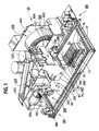
- FIG 1 is a perspective view of a biological sample testing machine or instrument 20 that conducts analysis of test sample filled cards 28 according to a preferred embodiment of the invention.
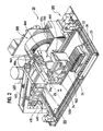
- the instrument 20 has a set of removable cover panels covering the machine and presenting an aesthetically pleasing appearance and allowing user access to system components, that are not shown, in order to better illustrate the functional aspects of the machine.
- a stacking card disposal station for the cards 28 has been removed in order to illustrate the other components of the instrument.
- the card disposal station 900 is shown in Figure 2 .
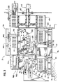
- Figure 3 is an end view of the machine, partially in section, showing the position of the test sample cards 28 as they are processed in several of the stations in the machine 20.
- Figure 1A is a block diagram of the machine 20 as a whole, showing the layout of the stations and the path of a boat and cassette assembly and test sample cards through the machine in a preferred embodiment of the invention.
- the biological sample testing machine 20 includes a biological test sample positioning system 100, consisting of four independent motor-driven paddles, which pulls a sample tray 22 (referred to herein as a "boat") incorporating a cassette 26 across a base pan 24 around the machine 20 to several discrete stations, where various operations are performed on the cards and receptacles in the cassette 26.
- a biological test sample positioning system 100 consisting of four independent motor-driven paddles, which pulls a sample tray 22 (referred to herein as a "boat") incorporating a cassette 26 across a base pan 24 around the machine 20 to several discrete stations, where various operations are performed on the cards and receptacles in the cassette 26.
- the cassette 26 consists of a holder that fits snugly into the boat 22 having a plurality of slots for receiving the test sample cards 28, with each of the slots having enough fore and aft separation distance so as to permit the cards 28 to be rocked slightly, in the manner described below, as the cassette 26 and boat 22 are moved past the bar code reading station 90 in the machine.
- a technician loads a cassette 26 with a plurality of test cards 28 and receptacles such as test tubes 30 containing biological or control samples to be tested.
- Each test card 28 has an L-shaped transfer tube 32 protruding therefrom for permitting the fluids containing biological samples to be drawn from the test tubes 30 into the reagent-filled wells of the test cards 28.
- the technician places the loaded cassette 26 into the boat 22 at a loading station for the machine, such as the front, right hand corner of the base pan 24 shown in Figure 1 .
- the combined boat 22 and loaded cassette 26 are then automatically moved as a unit over the surface of the base pan 24 about the machine 20 by the test sample positioning system 100.
- the test cards 28 come in two varieties: (1) identification cards, in which particular different growth media are placed in each of the wells of the card 28 when the cards are manufactured, and (2) susceptibility cards, in which different concentrations of different antibiotics are also placed in each of the wells of the card 28.
- the identification cards are used to identify the particular unknown biological agent, i.e., microorganism, present in the sample.
- the susceptibility cards are used to determine the susceptibility of the biological agent to various concentrations of antibiotics or other drugs.
- identification and susceptibility tests can be performed on a single sample in one cycle of operation of the machine 20 (i.e., one test run).
- the cassette 26 is loaded such that a test tube 30A containing a biological sample, connected via a transfer tube 32 to an identification card 28A, is placed adjacent to an empty test tube 30B connected via a transfer tube 32 to a susceptibility card 28B.
- the cards 28 preferably contain bar codes as well as other identifying indicia on the upper portion of the card for reading by a bar code reader 90 ( Figure 3 ) built into the machine 20.
- the bar codes are unique to each card, and identify card information such as card type, expiration date, and serial number, and are used to correlate test data and/or results from the cards with the patient and the biological sample.
- the entire boat or cassette may have sample information for all af the cards loaded in the cassette stored on one or more memory devices affixed to the cassette 26, such as a memory button or "touch button” available from Dallas Semiconductor Corp., 4401 S. Beltwood Parkway, Dallas Texas.
- a card identification reading station including a card separation device for promoting reading of the cards, is described in detail below.
- test tubes 30 in the boat 22 contain biological samples, and are in fluid communication with identification cards 28A by the straw-like transfer cube 32.
- the biological sample test tube 30A and its associated identification card 28A can be thought of as a set
- the biological sample test rubes and identification cards are typically arranged in an alternating pattern in the cassette 26.
- Each biological sample test tube 30A and identification card 28A set is adjacent to an empty test tube 30B placed in communication with a susceptibility card 28B via a transfer cube 32.
- the cards and associated test tubes could be ordered in any order in the cassette 26 depending on the particular testing requirements for the samples.
- the cards could be arranged as follows: identification (ID), susceptibility (SU), ID, ID, ID, SU, SU, ID, SU .... Further examples would be all identification cards and all susceptibility cards.
- the test sample positioning system 100 operates to move the boat 22 and cassette 26 over the base pan 24 to the bar code reading and card detection station 90, described below, and then to a diluting station 200.
- the diluting station contains a rotating shot tube 202, by which a predetermined volume of diluent (such as saline solution) is added to the empty susceptibility test tubes in the cassette 26, e.g. test tube 30B.
- a predetermined volume of diluent such as saline solution
- Other types of fluids may be added to the test tubes by a rotating shot tube, such as reagents or growth media, thus diluting station 200 is not limited to just adding a diluent to the test tubes.
- a pipetting station 300 As the leading edge of the boat 22 is moved to the left during this process, it passes under a pipetting station 300.
- the pipetting station 300 includes a mechanism that automatically removes a pipette 302 from a source of pipettes 304, lowers the pipette 302 into the biological sample test tube 30A, and removes with vacuum a predetermined volume of biological fluid from the biological sample test tube 30A using the pipette 302.
- the test sample positioning system 100 then moves the boat 22 to..the left by an amount equal to the separation distance between adjacent test tubes 30A and 30B, e.g. 15 mm.
- the pipetting station 300 then lowers the pipette 302 containing the biological fluid from the biological sample test tube 30A into the adjacent susceptibility test tube 30B (having already received a quantity of diluent from the diluting station 200), expels the fluid into the test tube 30B, mixes the fluid in the test cube 30B and drops the pipette 302 into the susceptibility test tube 30B.
- the test sample positioning system 100 then moves the boat 22 all the way to the left-hand edge of the base pan 24.
- the cassette 26 may be loaded entirely with biological samples in the test tubes 30 and identification cards 28, such as the case where a batch of biological samples are to be tested to identify the contents of the samples.
- identification cards 28 such as the case where a batch of biological samples are to be tested to identify the contents of the samples.
- the diluting and pipetting operations are not necessary.
- growth media, other diluents or reagents or fluids may be added to or withdrawn from the test tubes.
- the cassette 26 is loaded with test tubes and cards, and the positioning system 100 would simply move the boat 22 and loaded cassette 26 directly past the diluting station 200 and the pipetting station 300 without stopping, all the way to the left hand edge of the base pan 24.
- the test sample positioning system 100 operates to move the boat 22 along the left hand edge to a vacuum station 400.
- the vacuum station 400 is seen better in Figure 2 , which is a perspective view of the machine 20 with the diluting station 200 and the pipetting station 300 removed, and in Figures 4 and 5 ,
- a vacuum chamber 402 is lowered onto the boat 22 such that the bottom surface of the vacuum chamber 402 sealingly engages the top peripheral surface 23 of the boat 22.
- the vacuum chamber has tubing 406, 408 ( Figure 4 ) that are in communication with a conventional vacuum source for the machine (not shown in Figure 4 ).
- Vacuum is applied to the chamber 402 under microprocessor control, causing air in the interior of the test sample cards 28 to evacuate out of their associated test tubes and to be withdrawn from the chamber 402.
- the vacuum cycle is precisely managed to optimize filling by using a closed loop servo system to regulate the rate of change of vacuum and the timing of the complete vacuum cycle.
- the chamber 402 is vented to atmosphere under microprocessor control.
- the venting of the cards causes the fluid in the test tubes 30 to be drawn into the cards 28, filling the wells in the cards 28.
- the chamber is raised up by a vacuum chamber drive mechanism 410 so as to permit the boat to be moved to the other stations of the machine 20.
- the test sample positioning system 100 then operates to advance the boat 22 to the right across the rear of the base pan 24 to a cut and seal station 500, located behind the center mount 34 in Figures 1 and 2 .
- the cut and seal station 500 consists of a hot cutting wire 506 and attached support plate 504, and a drive mechanism 502 (e.g., stepper motor, drive belt and lead screw) that lowers the cutting wire and support plate 504 to the same elevation as the top portion of the transfer tubes 32 adjacent to where the transfer tubes 32 enter the test cards 28.
- the transfer tubes 32 are forced past the hot cutting wire 506.
- the hot cutting wire cuts the transfer tubes 32 by melting of the transfer tube material as the boat 22 is slowly advanced past the hot cutting wire 506.
- a small stub of transfer tube material is left on the exterior of the card 28. The stub seals the interior of the card 28 from the atmosphere (except, in certain types of cards, for possible diffusion of gasses such as oxygen through oxygen permeable tape covering the sample wells).
- test sample positioning system 100 then advances the boat 22 across the rear of the base pan 24 behind the center mount 34 to the inventive carousel incubation station 600.
- a reciprocating rack and pinion driver 610 is mounted to the center mount 34 opposite a slot 602 in the machine that pushes the cards off the cassette 26 one at a time through the slot 602 into a vertically oriented carousel 604.
- the carousel 604 is housed in an enclosure that is maintained at an appropriate incubation temperature. The enclosure is partially removed in Figures 1 and 2 in order to show the carousel 604.
- the carousel 604 is rotated by a drive system 612 in synchronism with the movement of the boat 22 over the rear of the base pan 24 by the test sample positioning system 100, so as to place the next slot in the carousel 604 in line with the slot 602 opposite the next card in the cassette 26.
- the operating system of the machine may control the carousel 604 rotation to load the cards into non-adjacent slots to equally distribute the cards in the carousel in order to balance out the weight distribution in the carousel 604. For example, where the carousel has 60 slots and only 30 cards are to be processed, the cards could be loaded into every other carousel slot
- Additional incubation capacity required for processing a larger number of cards at one time can be provided by using a larger carousel, adding an additional incubation station(s) to the base pan, and adjusting the dimension of the base pan and drive system components as necessary. Additional optics stations may be provided for additional carousels. For example, if the carousel 604 has sixty slots and each cassette holds 15 cards, four full cassettes 26 ( Figure 1 ) can be processed at once. If a second carousel is added, up to 120 cards could be processed at once. Of course, different capacities could be provided for the cassette 26 and the carousel 604.
- the boat 22 is advanced along the right hand edge of the base pan 24 back to its starting position (shown in Figures 1 and 2 ) or to an exit position for removal of the cassette 26 (containing the test tubes, pipettes 302. if any, and transfer tubes remnants) and receipt of a new cassette.
- the boat 22 could be moved to an exit station located, for example, in the rear or right hand side of the base pan 24.
- the cards 28 are periodically, sequentially pushed out of the slots of the carousel 604 at the top of the carousel 604, one at a time, by a reciprocating rack and pinion driver 620 and an associated stepper motor.
- the cards 28 are moved by an optical scanner card transport station 700 past a fluorescence and/or transmittance optics station 800 having a transmittance substation 302 and/or a fluorescence substation 804.
- the wells of the card 28 are selectively subject to sets of transmittance and/or fluorescence optical testing according to the analysis needed to be performed by the transmittance and fluorescence optics station 800.
- the transmittance and fluorescence optics station 800 includes detectors and processing circuitry to generate transmittance and fluorescence data for the wells in the cards 28, and to report the data to a central processing unit for the machine 20. If the test is not complete, the transport station 700 moves the card 28 back into its slot in the carousel 604 for more incubation and additional reading.
- each test sample card will be ejected into the transport station 700 for reading every 15 minutes as the carousel makes one revolution.
- the rate of rotation could be faster or slower, of course.
- Typical incubation times for the cards 28 are on the order of one to eighteen hours, consisting of roughly four transmittance and/or fluorescence data sets per hour, each data set consisting of multiple readings, for each of the wells in the card 28 subject to the optical analysis requirements.
- the card output station 900 consists of a detachable tray or magazine 902 and associated support structure that is positioned to the side of the optical station 800 at approximately the same elevation as the optical station 800.
- the station 900 has a pressure slide 914 that is moveable within the magazine 902 and a constant force spring biasing the pressure slide towards the front of the magazine.
- the cards are stacked in the magazine between the pressure slide 914 and oppositely opposed resilient snap elements integrally formed in the sides of the magazine 902. The technician removes the magazine 902 from the machine 20 as needed or when the magazine is full of cards, empties the cards into a suitable biohazard disposal unit, and replaces the magazine 902 back into the machine 20.
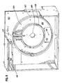
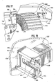
- Figure 6 is a front perspective view of the carousel 604 and incubation station 600 of Figure 1 , with several of the cover panels 619 of the incubation station removed in order to better illustrate the carousel 604.
- the cover panels 619 form an enclosure for the carousel 604 and isolate the carousel 604 from ambient conditions.
- the carousel 604 is vertically mounted and rotates about a horizontal axis.
- An air duct 622 is provided on the upper portion of the station 600 to allow air to circulate from the front portion of the incubation station (containing the carousel 604) to the rear of the station behind the bulkhead 652.
- a small hole is placed in the rear cover panel parallel to and positioned behind the bulkhead 652 to allow a controlled amount of ambient air into the station.
- the duct 622 includes an aperture in the bulkhead 652 to allow air to flow down the rear side of the bulkhead between the bulkhead and the rear cover panel, where it is blown over a heater which heats the air, and blown by a second fan 639 ( Figure 9 ) into an air distribution table 624 positioned behind the carousel 604, in the manner described in detail below.
- the carousel 604 has a plurality of slots 614 for receiving the test sample cards.
- the carousel has a substantially open front side portion 623 through which the cards are introduced into the slots 614 at the lowermost portion of the carousel (see Figure 3 ), and an opposite rear side portion facing the air table 624 and the bulkhead 652.
- FIG 7 is a perspective view of the incubation station of Figure 6 with the carousel 604 removed, in order to better illustrate the air table 624 and air distribution cover plate 625 features of the incubation station.
- the air table 624 receives warm air from a heater and fan assembly behind the bulkhead 652.
- the air table 624 has an air distribution cover plate 625 that encloses the air table 624 which is positioned in registry with the slots 614 of the carousel 604.
- the cover plate 625 has a plurality of elongate openings 626 formed therein that direct the warmed air over the rear side portion of the carousel and over the cards in the carousel slots.
- the rear side portion of the carousel adjacent to and opposite the air distribution cover plate 625 is substantially open and free of obstructions so as to permit substantially uninterrupted air flow over the test sample cards.
- Thin reinforcing ribs connecting the inner and outer circular carousel walls may be provided for strength and molding purposes, but such ribs should be sized so as to occupy a small as possible a surface area in the rear side portion of the carousel.
- the front portion of the carousel 604 is also spaced from the front cover panel (not shown) of the incubation station and made substantially open and free of obstructions, as shown, so as to promote the efficient recirculation of the air.
- the size and arrangement of openings 626 in the air distribution cover plate 625 is important to promoting the optimal air flow over the test sample cards and maintaining an even or uniform air temperature distribution over the test sample cards.
- the openings 626 are arranged in a manner such each of the openings 626 are oriented at an angle relative to the slots 614 of the carousel 604 such that the elongate openings 626 overlap at least two of the slots 614 of the carousel. This results in each card receiving air from at least two openings 626.
- the elongate openings 626 are preferably distributed in a symmetrical, ring-shaped pattern in substantial registry with the slots 614 in the carousel.
- at least 10 such openings 626 are provided, and in the embodiment 24 such openings are shown.
- the elongated openings are preferred over a design such as small holes so as to minimize the risk of dust and dirt clogging the slots and interfering with the air flow.
- the particular design of the openings is determined by the particular air flow characteristics for establishing uniform air flow distribution and providing a substantially constant and even temperature distribution in the incubation station.
- the design of the carousel may of course affect the design of the openings 626.
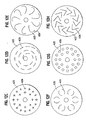
- FIG. 12A An arrangement of the openings 626 in concentric circles in registry with the carousel, as shown in Figure 12A .
- FIG. 12B Another possibility is forming the openings 626 as a plurality of overlapping arcuate segments as shown in Figure 12B .
- Other possibilities include rings of cross-shaped openings 626 ( Figure 12C ), elongate arcuate openings in a spiral pattern ( Figure 12D ), semicircular openings 626 arranged in a ring pattern ( Figures 12E and 12F ), a plurality of circular openings 626 arranged in concentric rings ( Figure 12G ), and a plurality of "L"-shaped openings 626 arranged in a ring ( Figure 12H ).
- Figure 8 is a perspective view of the incubation station of Figure 7 , with the cover plate 625 of the air table 624 removed in order to illustrate the internal structures of the air table 624.
- the air table 624 consists of a pair of circular walls 627 and 628 that define and enclose a ring-shaped region 630 in registry with the carousel.
- An opening 631 at the lower portion of the bulkhead 652 allows warmed air from the rear of the bulkhead 652 to be introduced into the ring-shaped region 630.
- the gap 617 at the top of the air table is to allow the reciprocating driver 620 ( Figure 3 ) to move through an aperture in the bulkhead 652 and push the test sample cards out of the top of the carousel into the test sample card transport station 700 of Figure 3 .
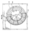
- Figure 12 is an isolated, elevational view of one section 670 of the carousel positioned over the mounting plate 673, showing the angled relationship of the elongate openings 626 in the air distribution cover plate 625 of the air table 624 with respect to the slots 614 in the carousel.
- FIG 9 is a perspective view of the rear portion of the incubation station 600 with the cover panels covering the rear of the station 600 removed, illustrating the drive system 612 that rotates the carousel 614.
- the drive system 612 comprises a stepper motor 632, a first belt 633, a second belt 634 and a pulley 635 that is rotated by belt 634.
- the pulley 635 is connected to a shaft 611 (see Figure 3 ) that passes through an aperture 609 in the bulkhead which is attached to and rotates the carousel 604.
- a first fan 637 is positioned behind and below the air duct 622 ( Figure 6 ) which blows ambient air down over a heater assembly 638 which warms the air.
- the air inlet hole in the rear cover panel (not shown) is above the elevation of the fan 637.
- a second fan 639 is positioned immediately behind the aperture 631 ( Figure 8 ) and directs air warmed by the heater 638 through the aperture 631 in the bulkhead and into the air table 624 of Figures 7 and 8 for distribution over the carousel 604.
- Thermistors are provided, one in the rear of the bulkhead below the heater 638 and one behind the air distribution cover plate of air table 624 for controlling the operation of the heater and the temperature of the air exiting the air table 624.
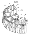
- the carousel 604 is constructed as a plurality of discrete, separable arcuate carousel segments or sections, such as four pie-shaped segments, each referred to as a "quad” or a "quadrocell", each of the segments separately removable from the incubation station enclosure in order to facilitate easy removal of the carousel for clearing or maintenance.
- Figure 10 is an isolated perspective view of one such segment 670 of the carousel 604.
- the segment comprises a first end wall 671, a second end wall 672, an inner arcuate wall 673, and a concentric outer arcuate wall 674.
- the rear side 675 portion is substantially open, allowing air to circulate from the slots 626 in the air distribution cover plate of the air table of Figure 7 to freely pass over test sample cards placed in the slots 614.
- the slots 614 have opposed ramp faces 614A ( Figures 10 and 11 ) to promote the easy insertion of the test sample cards into the slots 614.
- a least one reinforcing rib 676 is provided that extends between the inner wall 673 to the outer wall 674 to give adequate strength to the carousel segment 670 and improve moldability of the segment 670.
- the end walls 672 are formed with substantial scalloped void regions 669, which has been found to improve the air flow over the test sample cards.
- the front surface of the carousel segment is spaced from the front cover panel of the incubation enclosure to allow efficient air return via duct 622 ( Figure 6 ).
- a mounting flange 677 is provided integral with the inner wall 673 which is used to mount the segment 670 to a mounting plate 678. ( Figure 11 ) connected to the end of the drive shaft 609 ( Figure 3 ).
- the mounting flange 677 has a guide ramp 681 to assist in placement of a pair of downwardly depending cylindrical legs or projections 679 formed on the bottom surface of the flange 677 into a pair of corresponding holes 680 formed in the mounting plate 678.
- the segment 670 is held in place by the action of a spring loaded pin 682 positioned within a retaining hub 683 clamping the flange 677 against the mounting plate 678.
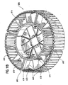
- Figure 11A is a perspective view of the rear of two carousel segment 670A and 670B in which a plurality of upstanding tabs 691 are provided on the rear surface 675 of the outer peripheral arcuate wall 674.
- Figure 11B is a perspective view of the rear of an entire carousel. 604. The tabs 691 are positioned in registry with the carousel slots 614.
- the tabs 691 are used in conjunction with an optical position sensor 693 comprising a slotted optical switch that is positioned adjacent to the bulkhead 652 ( Figure 8 ) within the incubation station immediately behind the rear surface 675 of the carousel such that the tabs 691 pass in the slot 694 between the emitter 695 and detector 696 of the optical position sensor 693 ( Figure 11A ) as the carousel rotates.
- an optical position sensor 693 comprising a slotted optical switch that is positioned adjacent to the bulkhead 652 ( Figure 8 ) within the incubation station immediately behind the rear surface 675 of the carousel such that the tabs 691 pass in the slot 694 between the emitter 695 and detector 696 of the optical position sensor 693 ( Figure 11A ) as the carousel rotates.
- the optical position sensor 693 is mounted in any convenient position adjacent to the bulkhead such that the placement of a tab 691 between the emitter and detector results in the slots 614 of the carousel being correctly placed to receive a test sample card from the card loading mechanism 610 of Figure 3 , and correctly placed for the card ejection mechanism 648 of Figure 17 and 18 to push a test sample card out of the slot 614 in the carousel. It is important that the optical interrupts are positioned such that there is a gap between the carousel segments 670A and 670B in the location 697.
- Figure 13 is a perspective view of the carousel 604 in an installed condition showing the easy manual removal and insertion of a section 670 of the carousel 604 from the instrument 20.
- Figure 14 is a perspective view of the section 670 of the carousel 604 installed.
- Figure 15 is a detailed perspective view of the spring loaded pin 682, mounting plate 678 and flange 677 of the carousel section 670.
- the spring loaded pin 682 rides up the ramp 681 against the force of a biasing spring (not shown) inside the hub 683.
- the front surface 685 of the flange 677 abuts the flat planar portion 686 of the hub 683, positioning the cylindrical legs 679 ( Figure 10 ) into the holes 680.
- the spring loaded pin 682 then presses against the flat planar portion 687 of the flange 677 to lock it in place.
- Figure 16 is detailed perspective view of a section 670 of the carousel being inserted, showing the ramp 681 in alignment with the spring loaded pin 682 immediately before the section 670 is locked into place.
- Figure 17 is a perspective view of a push mechanism 648 located at the top of the bulkhead of Figure 6 that pushes the cards out of the slots in the carousel of FIG. 2 into the sample card transport system 706, 704, 710 and 718 of Figure 1 .
- the air table has been removed in order to better illustrate the push mechanism.
- Figure 18 is a perspective view of the push mechanism as seen from the rear of the bulkhead. Referring to Figures 17 and 18 , in order to place the card 28 into the sample card transport system 700, a rack and pinion push mechanism 648 is provided to push the card 28 out of the carousel 604.
- the push mechanism includes an alignment block 654 mounted to the bulkhead 652 and a driver 656 chat reciprocates back and forth relative to the block 654.
- a motor 648 having a gear 662 is mounted behind the bulkhead 652.
- the teeth of the gear 662 cooperate with a set of teeth 658 on the driver 656, such that rotation of the gear 662 backwards and forwards causes the driver 658 to move in the direction shown by the arrow 664 ( Figure 18 ) in the space between a lower slot 666 and an upper slot 668 in the block 654.
- the end of the driver 656 is positioned in alignment with the top slot 614 in the carousel 604.
- the card transport station 700 includes a cover plate 704, a card slot 706 defined between a drive belt 710 and the ledge 718 to move the cards 28 back and forth between the carousel 604 and the optical stations 802 and 804 of Figures 1 and 3 . Further details on this drive system are set forth in greater detail in the above-referenced patent application of Mark J. Fanning et al. serial no. 08/604,672 which is incorporated by reference herein.
- Figure 19 is a graph of the growth curves of microorganisms in the wells of the cards as a function of time for the incubation station and Instrument of the preferred embodiment described in Figures 6-18 (line 690), as compared to the growth curves for the instrument without the improved air flow features (line 692).
- Line 690 indicates that after a few hours of incubation, at time t1 the growth of the microorganism begins to increase at a steady rate until time t2, when the growth levels off.
- the cards are moved in and out of the incubation station and shuttled back and forth to the optical stations for reading.
- the light transmittance characteristics have changed from an initial measurement at time t1 such that that a positive reading of the well would occur in the optical system at time t3.
- the improved air flow techniques of the present invention improve oxygen transfer through the oxygen-transmissible tape that covers the wells of the card. Since the reactions occurring within the cards are typically aerobic reactions, increasing the supply of oxygen helps promote the reaction within the wells of the card and shorten the time needed to obtain a test result.
- the organism growth does not begin until about time t3, and reaches a maximum at time t4.
- Time t5 is later than time t3 by an amount ⁇ t, which could be as much as several hours.
- Figure 20 is a graph of temperature as a function of time inside the incubation station for a four hour period, showing the very small temperature variation that occurs inside incubation station in accordance with the invention. Without the above-referenced air flow improvements, air temperature variation away from the desired temperature of 35.5 degrees C in the incubation station was on the order of several degrees C, whereas with the improvements it was reduced to less than 1 degree C over a four hour period. This even temperature characteristic would be expected to be maintained for longer incubation periods, such as 12 or 18 hours.
- Figure 21 is a graph of the growth versus time difference profile for sample wells in a test sample card incubated shown in Figure 3 , in an incubation station that does not have the improved air flow features described herein, for example, without the second fan, without a reduced width quadrocell, without the open rear of the carousel, and using a single opening for air distribution instead of slots in the cover plate of the air table ( Figure 7 ).
- the growth profiles of some of the bacteria or antibiotic combinations are directly related to the temperature (and air flow)in the slots of the carousel, with greater temperatures and air flow may result in faster growth and lower temperatures and less air flow may result in slower growth. Even temperature and air flow and hence growth across all the wells is the desired result.
- Figure 21 illustrates the undesirable wide variation in growth time across the cards, with the wells at in the eighth or left hand column S8 having markedly longer growth times as compared to the wells in the first column S1.
- Figure 22 is a graph of the growth time profile for sample wells in a test sample card incubated in an incubation station that has all of the improved air flow features described herein, showing the substantially reduced variation in growth time across the cards. While columns S3-S8 exhibit slightly longer growth times as compared to column S1, the difference is much less pronounced than that shown in Figure 21 . The difference in growth time profiles shown in Figure 22 would not be expected to adversely impact the sample testing procedure. Further, by virtue of the rotation of the carousel at a rate of one revolution per 15 minutes, and all incubation times being on the order of more than one hour, each card in the carousel 604 would be expected to exhibit the temperature pattern and hence growth profile shown in Figure 22 .
- a card separation device comprising a wheel 94 attached to an arm that pivots about a pin 98 is shown.
- the wheel 94 rocks the cards 28 back within the slots of the cassette 26 to expose the upper surface of the card 28 and bar code affixed at this location to an optical reader 90 located forward of and above the card in the machine.
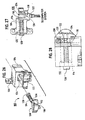
- Figure 23 is an isolated perspective view of an alternative and more preferred card separation device 102 that is also capable of card detection.
- Figure 24 is a side elevational view of the card separation and detection device 102.
- Figure 25 is a front elevation view of the device 102.
- Figure 26 is an exploded perspective view of the device 102.
- the device 102 is mounted to a flange off of the center mount 34 in essentially the same manner and location as shown for the device 94 in Figure 3 , in a position "upstream" of the reading device 90 and in optical alignment with the reading device 90.
- the card separation and detection device 102 includes a housing 104 having flanges 106 that are attached to structures in the instrument (such as cross-member 92 or mounting flange 91 depending from cross-member 92 in Figure 3 ) in proximity to the pathway that the cards 28 move along within the-instramenl In Figure 3 , the motion of the boat 22 on the lower left hand side of the illustration is into the page, thus the card separation device separates the cards 28 as the cards are moved past the device so that the optical reader 90 can read bar codes positioned at the top of the card facing the optical reader 90.
- structures in the instrument such as cross-member 92 or mounting flange 91 depending from cross-member 92 in Figure 3
- the device 102 includes an actuator 108 reciprocating relative to the housing 104 between a first or extended position and a second or retracted position.
- the actuator 108 has a head portion 110 with a first card contact surface 112.
- the actuator 108 is moved by the card from its extended position, against the force of a biasing spring 114 surrounding a threaded shoulder screw 120, to a retracted position relative to the housing 104 in the manner suggested by the arrow in Figure 23 .
- the actuator 108 carries an optical interrupt flag 118 on the lower surface 120 of the head portion 110.
- the flag 118 is moved into the optical path of an optical detector 122.
- the optical detector 122 is mounted to the housing 104 immediately below the actuator 108. The movement of the flag 118 into the optical path of the detector 122 triggers the optical detector 122, and sends a signal to the central computer system for the instrument indicating that a card was detected by the device 102.
- the action of the card 28 contacting the surface 112 actuator 108 also results in a movement of the card relative to the cassette and the automated reading station 90 such that the indicia or bar codes positioned on the top edge of the cards 28 are better positioned for reading by the reader 90.
- the card is rocked back in the slot in the cassette 26 to an angle, and moved away from the card in front of it in the cassette 26, such that the bar code or other indicia is clearly exposed to the reader 90.
- the actuator 108 is moved by the biasing spring 114 back to its first or extended position, at which time a second card contact surface 124 contacts the card 28 and pushes the card forward in the slot in the cassette 26. This helps separate one card from the next in the cassette.
- the actuator 108 reciprocates in an oval aperture 124 in the housing 104.
- the shoulder 126 of the actuator 108 is given an oval cross-sectional shape and dimension so as to fit inside to the aperture 124 and not result in any rotational or side to side translational motion.
- Figure 27 is a side view of the device 102 in an assembled condition, partially in section, showing the position of the threaded shoulder screw 120 within the body of the housing 104, and the flag 118 on the actuator relative to the optical sensor 122 when the actuator 108 is in the extended position. Note that when the actuator 108 is moved to the retracted position, the flag 118 is moved into the optical path 130 of the optical sensor 122. Note also in Figure 27 that the spring 114 has one end thereof that seats against the rear surface of the head portion 110, and a second end that seats against an inner vertical wall 132 in the housing 104.
- the threaded shoulder screw 120 has a tip 134 that is connected to the head 110. A clearance exists between the head 110 and the walls of the aperture 124 (see Figure 26 ) allowing the head 110 of the actuator 108 to freely move back and forth within the aperture 124.
- Figure 28 is a bottom plan view of the device, partially in section, showing the position of the shoulder screw 120 within the housing 104.
- a screw 138 mounts the optical sensor 122 to the housing 104 in proximity with the flag 118 such that the flag 118 reciprocates with the actuator 108 into the space between the source and detector of the optical sensor 122.
Landscapes
- Chemical & Material Sciences (AREA)
- Health & Medical Sciences (AREA)
- Analytical Chemistry (AREA)
- General Health & Medical Sciences (AREA)
- General Physics & Mathematics (AREA)
- Pathology (AREA)
- Immunology (AREA)
- Physics & Mathematics (AREA)
- Life Sciences & Earth Sciences (AREA)
- Biochemistry (AREA)
- Clinical Laboratory Science (AREA)
- Chemical Kinetics & Catalysis (AREA)
- Hematology (AREA)
- Automatic Analysis And Handling Materials Therefor (AREA)
- Apparatus Associated With Microorganisms And Enzymes (AREA)
- Investigating Or Analysing Materials By The Use Of Chemical Reactions (AREA)
- Investigating Or Analysing Materials By Optical Means (AREA)
- Conveying Record Carriers (AREA)
- Controlling Sheets Or Webs (AREA)
- Geophysics And Detection Of Objects (AREA)
Applications Claiming Priority (2)
| Application Number | Priority Date | Filing Date | Title |
|---|---|---|---|
| US08/905,374 US6156565A (en) | 1996-02-21 | 1997-08-04 | Incubation station for test sample cards |
| EP98304820A EP0896224B1 (fr) | 1997-08-04 | 1998-06-18 | Station d'incubation pour catres de test |
Related Parent Applications (2)
| Application Number | Title | Priority Date | Filing Date |
|---|---|---|---|
| EP98304820.8 Division | 1998-06-18 | ||
| EP98304820A Division EP0896224B1 (fr) | 1997-08-04 | 1998-06-18 | Station d'incubation pour catres de test |
Publications (2)
| Publication Number | Publication Date |
|---|---|
| EP1923706A2 true EP1923706A2 (fr) | 2008-05-21 |
| EP1923706A3 EP1923706A3 (fr) | 2010-10-20 |
Family
ID=25420721
Family Applications (3)
| Application Number | Title | Priority Date | Filing Date |
|---|---|---|---|
| EP08075035A Withdrawn EP1923706A3 (fr) | 1997-08-04 | 1998-06-18 | Dispositif de détection de carte |
| EP08075036A Withdrawn EP1912071A3 (fr) | 1997-08-04 | 1998-06-18 | Carrousel pour un dispositif d'analyse |
| EP98304820A Expired - Lifetime EP0896224B1 (fr) | 1997-08-04 | 1998-06-18 | Station d'incubation pour catres de test |
Family Applications After (2)
| Application Number | Title | Priority Date | Filing Date |
|---|---|---|---|
| EP08075036A Withdrawn EP1912071A3 (fr) | 1997-08-04 | 1998-06-18 | Carrousel pour un dispositif d'analyse |
| EP98304820A Expired - Lifetime EP0896224B1 (fr) | 1997-08-04 | 1998-06-18 | Station d'incubation pour catres de test |
Country Status (10)
| Country | Link |
|---|---|
| US (3) | US6156565A (fr) |
| EP (3) | EP1923706A3 (fr) |
| JP (1) | JP3354100B2 (fr) |
| KR (1) | KR100291650B1 (fr) |
| AU (1) | AU726007B2 (fr) |
| BR (1) | BR9802811A (fr) |
| CA (1) | CA2230972C (fr) |
| DE (1) | DE69839031T2 (fr) |
| ES (1) | ES2300117T3 (fr) |
| IL (1) | IL124363A (fr) |
Families Citing this family (68)
| Publication number | Priority date | Publication date | Assignee | Title |
|---|---|---|---|---|
| EP0901634B1 (fr) * | 1996-05-30 | 2002-03-20 | Radiometer Medical A/S | Systeme de determination d'au moins un parametre d'au moins un echantillon d'un liquide physiologique et cassette |
| AU753745B2 (en) * | 1998-04-24 | 2002-10-24 | Roche Diagnostics Gmbh | Storage container for analytical devices |
| AU2006230730B2 (en) * | 1998-05-01 | 2009-03-05 | Gen-Probe Incorporated | Multiple ring assembly for providing specimen to reaction receptacles within an automated analyzer |
| US8337753B2 (en) | 1998-05-01 | 2012-12-25 | Gen-Probe Incorporated | Temperature-controlled incubator having a receptacle mixing mechanism |
| ES2286750T3 (es) * | 1998-05-01 | 2007-12-01 | Gen-Probe Incorporated | Dispositivo para agitar el contenido liquido de un contenedor. |
| DE19902601A1 (de) * | 1999-01-23 | 2000-07-27 | Roche Diagnostics Gmbh | Verfahren und Vorrichtung zum Entnehmen analytischer Verbrauchsmittel aus einem Vorratsbehältnis |
| WO2001028680A2 (fr) * | 1999-10-20 | 2001-04-26 | Gentra Systems, Inc. | Appareil a melanger et a verser et recipient correspondant |
| USD448087S1 (en) | 2000-05-23 | 2001-09-18 | Packard Instrument Company, Inc. | Microarray slide cassette |
| US6597719B1 (en) * | 2000-08-21 | 2003-07-22 | Komatsu Ltd. | Once through fan for gas laser apparatus and gas laser apparatus therewith |
| JP4681749B2 (ja) * | 2001-03-28 | 2011-05-11 | キヤノン株式会社 | プローブ担体の管理方法、プローブ担体製造装置及びプローブ担体管理装置 |
| US7312084B2 (en) * | 2001-07-13 | 2007-12-25 | Ortho-Clinical Diagnostics, Inc. | Tandem incubator for clinical analyzer |
| US7666363B2 (en) * | 2001-09-05 | 2010-02-23 | Quest Diagnostics Investments Incorporated | Reagent cartridge |
| US7584240B2 (en) | 2001-11-07 | 2009-09-01 | Genvault Corporation | Automated biological sample archive for storage, retrieval and analysis of large numbers of samples for remote clients |
| US20030087455A1 (en) * | 2001-11-07 | 2003-05-08 | Eggers Mitchell D | Sample carrier system |
| US20030087425A1 (en) * | 2001-11-07 | 2003-05-08 | Eggers Mitchell D | Sample carrier |
| US7468161B2 (en) | 2002-04-15 | 2008-12-23 | Ventana Medical Systems, Inc. | Automated high volume slide processing system |
| WO2003089140A1 (fr) | 2002-04-15 | 2003-10-30 | Ventana Medical Systems, Inc. | Systeme de coloration de lame automatique a volume de traitement eleve |
| US11249095B2 (en) | 2002-04-15 | 2022-02-15 | Ventana Medical Systems, Inc. | Automated high volume slide processing system |
| US7718442B2 (en) * | 2002-11-22 | 2010-05-18 | Genvault Corporation | Sealed sample storage element system and method |
| US20100075858A1 (en) * | 2003-04-29 | 2010-03-25 | Genvault Corporation | Biological bar code |
| WO2004099787A1 (fr) * | 2003-05-05 | 2004-11-18 | Visible Diagnostics A/S | Systeme de transport automatique d'echantillons et utilisation de ce systeme |
| FR2855614B1 (fr) * | 2003-05-28 | 2005-07-08 | Biomerieux Sa | Systeme de controle de la temperature au sein d'un automate d'analyse biologique reduisant la variation thermique entre les temperatures d'entree et de sortie de l'air |
| US7632675B2 (en) * | 2003-06-05 | 2009-12-15 | Bioprocessors Corp. | Apparatus and method for manipulating substrates |
| AU2004245123A1 (en) * | 2003-06-05 | 2004-12-16 | Bioprocessors Corp. | System and method for process automation |
| US7273591B2 (en) | 2003-08-12 | 2007-09-25 | Idexx Laboratories, Inc. | Slide cartridge and reagent test slides for use with a chemical analyzer, and chemical analyzer for same |
| US7578978B2 (en) * | 2003-10-28 | 2009-08-25 | BIOMéRIEUX, INC. | Carrier for holding test samples |
| US7429355B2 (en) * | 2003-10-28 | 2008-09-30 | Biomerieux, Inc. | Sealer for test sample devices |
| US7510681B2 (en) * | 2003-10-28 | 2009-03-31 | BIO MéRIEUX, INC. | Transport system for test sample carrier |
| US7601300B2 (en) * | 2003-10-28 | 2009-10-13 | BIOMéRIEUX, INC. | Compact, integrated system for processing test samples |
| US7588733B2 (en) | 2003-12-04 | 2009-09-15 | Idexx Laboratories, Inc. | Retaining clip for reagent test slides |
| DE602005016402D1 (de) | 2004-05-24 | 2009-10-15 | Genvault Corp | Stabile lagerung von protein und stabile lagerung von nukleinsäure in wiedergewinnbarer form |
| EP1765487A1 (fr) * | 2004-06-07 | 2007-03-28 | Bioprocessors Corporation | Melange de reacteur |
| EP1758674A2 (fr) * | 2004-06-07 | 2007-03-07 | Bioprocessors Corporation | Creation de cisaillement dans un reacteur |
| GB0502556D0 (en) * | 2005-02-08 | 2005-03-16 | Lab901 Ltd | Analysis instrument |
| US7964413B2 (en) | 2005-03-10 | 2011-06-21 | Gen-Probe Incorporated | Method for continuous mode processing of multiple reaction receptacles in a real-time amplification assay |
| CN2862037Y (zh) * | 2005-12-12 | 2007-01-24 | 深圳迈瑞生物医疗电子股份有限公司 | 用于全自动生化分析仪的一次性反应杯链 |
| WO2008140742A1 (fr) | 2007-05-08 | 2008-11-20 | Idexx Laboratories, Inc. | Analyseur chimique |
| WO2010031007A2 (fr) | 2008-09-12 | 2010-03-18 | Genvault Corporation | Matrices et support pour le stockage et la stabilisation de biomolécules |
| CA2742473C (fr) | 2008-11-12 | 2015-02-24 | Ventana Medical Systems, Inc. | Procedes et appareils permettant de chauffer des lames portant des echantillons |
| US9046507B2 (en) | 2010-07-29 | 2015-06-02 | Gen-Probe Incorporated | Method, system and apparatus for incorporating capacitive proximity sensing in an automated fluid transfer procedure |
| WO2012048096A2 (fr) | 2010-10-08 | 2012-04-12 | Biomerieux, Inc. | Cartes de tests d'échantillons améliorées |
| BR112013008588B1 (pt) | 2010-11-23 | 2020-05-12 | Biomerieux Inc. | Cartões de teste de amostra |
| AU2012222178B2 (en) | 2011-02-24 | 2014-12-18 | Gen-Probe Incorporated | Systems and methods for distinguishing optical signals of different modulation frequencies in an optical signal detector |
| US9606103B2 (en) | 2011-12-16 | 2017-03-28 | Siemens Healthcare Diagnostics Inc. | Waste ramp for reagent cards |
| EP3964839B1 (fr) | 2013-03-15 | 2024-04-10 | Abbott Laboratories | Analyseurs diagnostiques automatiques comprenant des systèmes de rail accessibles par l'arrière et procédés associés |
| CN109358202B (zh) | 2013-03-15 | 2023-04-07 | 雅培制药有限公司 | 具有竖直布置的圆盘传送带的自动化诊断分析仪及相关方法 |
| CN105190317B (zh) | 2013-03-15 | 2018-05-04 | 雅培制药有限公司 | 具有预处理转盘的诊断分析机及相关方法 |
| CN111089980B (zh) | 2013-12-13 | 2023-08-15 | 文塔纳医疗系统公司 | 生物样本的自动化组织学处理及相关的技术 |
| US9797916B2 (en) | 2014-01-10 | 2017-10-24 | Idexx Laboratories, Inc. | Chemical analyzer |
| WO2016120930A1 (fr) * | 2015-01-30 | 2016-08-04 | パナソニックIpマネジメント株式会社 | Dispositif de transfert robotique |
| CN105759067B (zh) * | 2016-04-27 | 2018-01-09 | 王治才 | 一种试剂卡存放结构和多项目检测装置 |
| BR112019012579B1 (pt) | 2016-12-23 | 2023-01-24 | Biomèrieux, Inc | Cartão de teste com plataforma de cavidade |
| CN107966441B (zh) * | 2017-12-04 | 2024-12-06 | 珠海迪尔生物工程股份有限公司 | 一种大便分析仪的检测系统 |
| USD889683S1 (en) | 2017-12-22 | 2020-07-07 | Biomerieux, Inc. | Test card |
| EP3561517B1 (fr) * | 2018-04-25 | 2021-04-21 | Aoi Seiki Co., Ltd. | Appareil de transport de supports |
| CN110967496B (zh) * | 2018-09-29 | 2023-11-10 | 深圳市帝迈生物技术有限公司 | 样本分析仪 |
| MX2021011349A (es) | 2019-03-22 | 2021-10-13 | Siemens Healthcare Diagnostics Inc | Analizador de muestras biologicas con deteccion de consumible frio. |
| AU2020247732A1 (en) | 2019-03-22 | 2021-09-16 | Siemens Healthcare Diagnostics Inc. | Biological sample analyzer with forced air convection plenum |
| JP7296478B2 (ja) | 2019-03-22 | 2023-06-22 | シーメンス・ヘルスケア・ダイアグノスティックス・インコーポレイテッド | 熱的な加温を加速する生体試料分析装置 |
| CN110514858B (zh) * | 2019-08-21 | 2024-06-18 | 成都斯马特科技股份有限公司 | 一种全自动化学发光免疫分析用试剂包装置 |
| CN110514859B (zh) * | 2019-08-21 | 2021-03-16 | 成都斯马特科技有限公司 | 一种全自动化学发光免疫分析方法 |
| CN110724626B (zh) * | 2019-11-13 | 2022-05-10 | 北京航宇阳光机电技术研究所 | 一种生物芯片的集成检测装置 |
| CN111337481B (zh) | 2020-04-26 | 2024-07-09 | 成都斯马特科技股份有限公司 | 一种化学发光免疫分析仪 |
| CN111635854B (zh) * | 2020-07-02 | 2022-04-12 | 中国人民公安大学 | 一种微生物检测试剂盒 |
| CN115836207B (zh) | 2020-07-10 | 2026-04-24 | Idexx实验室公司 | 护理点医学诊断分析仪、以及用于对样品进行医学诊断分析的装置、系统和方法 |
| CN111808719B (zh) * | 2020-07-24 | 2023-12-22 | 江苏绿科生物技术有限公司 | 一种用于养殖环境改良的微生物菌培养装置 |
| CN112903396B (zh) * | 2021-03-02 | 2022-11-15 | 东北石油大学 | 断裂韧性实验岩心开槽工具及其开槽方法 |
| CN115855823B (zh) * | 2022-12-29 | 2026-04-17 | 广东唯实生物技术有限公司 | 一种光学检验装置 |
Citations (6)
| Publication number | Priority date | Publication date | Assignee | Title |
|---|---|---|---|---|
| US4038151A (en) | 1976-07-29 | 1977-07-26 | Mcdonnell Douglas Corporation | Card for use in an automated microbial detection system |
| US4116775A (en) | 1976-05-03 | 1978-09-26 | Mcdonnell Douglas Corporation | Machine and process for reading cards containing medical specimens |
| US4118280A (en) | 1976-05-03 | 1978-10-03 | Mcdonnell Douglas Corporation | Automated microbial analyzer |
| US4318994A (en) | 1979-08-30 | 1982-03-09 | Mcdonnell Douglas Corporation | Enterobacteriaceae species biochemical test card |
| US5609828A (en) | 1995-05-31 | 1997-03-11 | bio M erieux Vitek, Inc. | Sample card |
| US5762873A (en) | 1996-02-21 | 1998-06-09 | Biomerieux Vitek, Inc. | Automatic sample testing machine |
Family Cites Families (41)
| Publication number | Priority date | Publication date | Assignee | Title |
|---|---|---|---|---|
| US4219529A (en) * | 1977-11-28 | 1980-08-26 | Eastman Kodak Company | Incubator for chemical analyzer |
| US4250266A (en) * | 1979-12-19 | 1981-02-10 | Honeywell Inc. | Automated micro-organism culture growth and detection instrument |
| US4287155A (en) * | 1980-06-16 | 1981-09-01 | Eastman Kodak Company | Sample tray and carrier for chemical analyzer |
| JPS58120165A (ja) * | 1982-01-13 | 1983-07-16 | Toshiba Corp | 恒温装置 |
| FR2567538B1 (fr) * | 1984-07-12 | 1986-12-26 | Inst Nat Sante Rech Med | Automate pour l'analyse et le clonage de cultures cellulaires ainsi que pour l'analyse bacteriologique |
| US5108703A (en) * | 1986-03-26 | 1992-04-28 | Beckman Instruments, Inc. | Automated multi-purpose analytical chemistry processing center and laboratory work station |
| US4713974A (en) * | 1986-04-18 | 1987-12-22 | Varian Associates, Inc./Scientific Systems, Inc. | Autosampler |
| US4900168A (en) * | 1986-06-23 | 1990-02-13 | National Business Systems, Inc. | Credit card transporting embossing and recording system |
| US4956148A (en) * | 1987-04-22 | 1990-09-11 | Abbott Laboratories | Locking rack and disposable sample cartridge |
| IT1221246B (it) * | 1988-02-04 | 1990-06-27 | Sgs Thomson Microelectronics | Alimentatore con tensione di uscita sviluppata gradualmente all' atto dell' accensione |
| US4795710A (en) * | 1988-02-26 | 1989-01-03 | Eastman Kodak Company | Mounting of analyzer sample tray |
| FR2634893B1 (fr) * | 1988-07-28 | 1990-09-14 | Guigan Jean | Laboratoire miniature pour la realisation d'analyses biologiques par reaction chimique a partir d'un echantillon de sang |
| US5133936A (en) * | 1988-09-07 | 1992-07-28 | Hitachi, Ltd. | Constant-temperature air type automatic analysis apparatus |
| GB9020352D0 (en) * | 1990-09-18 | 1990-10-31 | Anagen Ltd | Assay or reaction apparatus |
| US5171530A (en) * | 1990-02-28 | 1992-12-15 | The Perkin-Elmer Corporation | Vial locator and sensor |
| US5595707A (en) * | 1990-03-02 | 1997-01-21 | Ventana Medical Systems, Inc. | Automated biological reaction apparatus |
| JP3186764B2 (ja) * | 1990-03-02 | 2001-07-11 | ベンタナ・メデイカル・システムズ・インコーポレーテツド | 自動化生物学的反応装置 |
| US5290517A (en) * | 1990-04-04 | 1994-03-01 | Westinghouse Electric Corp. | Optical agglutination assay device |
| US5207987A (en) * | 1990-05-21 | 1993-05-04 | Pb Diagnostic Systems Inc. | Temperature controlled chamber for diagnostic analyzer |
| US5200151A (en) * | 1990-05-21 | 1993-04-06 | P B Diagnostic Systems, Inc. | Fluid dispensing system having a pipette assembly with preset tip locator |
| US5080864A (en) * | 1990-07-20 | 1992-01-14 | Eastman Kodak Company | Stopper detector |
| FR2672126B1 (fr) * | 1990-11-16 | 1994-04-08 | Alcyon Analyser Sa | Segment reactionnel pour analyseur automatique d'echantillons et analyseur equipe d'un segment. |
| US5192506A (en) * | 1991-02-14 | 1993-03-09 | P B Diagnostic Systems, Inc. | Incubator port closure for automated assay system |
| US5113938A (en) * | 1991-05-07 | 1992-05-19 | Clayton Charley H | Whipstock |
| US5246665A (en) * | 1991-06-03 | 1993-09-21 | Abbott Laboratories | Heat and air flow control for assay carrier |
| US5324481A (en) * | 1991-06-03 | 1994-06-28 | Abbott Laboratories | Carousel for assay specimen carrier |
| AU656826B2 (en) * | 1991-10-31 | 1995-02-16 | Microscan, Inc. | Specimen processing and analyzing systems with associated fluid dispensing apparatus |
| EP0592624B1 (fr) * | 1992-03-09 | 2001-09-19 | Accumed International Inc. | Procede et appareil pour le diagnostic microbiologique |
| US5646049A (en) * | 1992-03-27 | 1997-07-08 | Abbott Laboratories | Scheduling operation of an automated analytical system |
| US5610069A (en) * | 1992-03-27 | 1997-03-11 | Abbott Laboratories | Apparatus and method for washing clinical apparatus |
| US5397539A (en) * | 1992-04-23 | 1995-03-14 | Toray Industries, Inc. | Automatic analyzing apparatus |
| JP3193443B2 (ja) * | 1992-04-24 | 2001-07-30 | オリンパス光学工業株式会社 | 自動分析装置 |
| ES2259277T3 (es) * | 1993-09-24 | 2006-10-01 | Abbott Laboratories | Metodo de operar de un sistema analitico automatico de acceso aleatorio continuo capaz de efectuar simultaneamente ensayos multiples en una pluralidad de muestras de liquidos. |
| US5374395A (en) * | 1993-10-14 | 1994-12-20 | Amoco Corporation | Diagnostics instrument |
| US5585707A (en) * | 1994-02-28 | 1996-12-17 | Mcdonnell Douglas Corporation | Tendon suspended platform robot |
| US5573950A (en) * | 1994-05-11 | 1996-11-12 | Minnesota Mining And Manufacturing Company | Cassette for disposable microorganism culturing media and automated scanning system |
| US5433922A (en) * | 1994-05-27 | 1995-07-18 | Coulter Corporation | Self-adjusting tube detector |
| JP3251441B2 (ja) * | 1994-09-30 | 2002-01-28 | シスメックス株式会社 | キュベットおよびキュベット搬送装置 |
| US5863754A (en) * | 1995-05-12 | 1999-01-26 | Pasteur Sanofi Diagnostics | Process for bacteria identification and for determination of the sensitivity of bacteria to antibiotics and apparatus and measuring supports for carrying out this process |
| US5738827A (en) * | 1995-08-23 | 1998-04-14 | Ljl Biosystems, Inc. | Apparatus for holding reagent and sample vessels |
| AU715627B2 (en) * | 1996-02-21 | 2000-02-03 | Biomerieux Vitek, Inc. | Automatic sample testing machine |
-
1997
- 1997-08-04 US US08/905,374 patent/US6156565A/en not_active Expired - Lifetime
-
1998
- 1998-03-04 CA CA002230972A patent/CA2230972C/fr not_active Expired - Lifetime
- 1998-05-07 IL IL12436398A patent/IL124363A/xx not_active IP Right Cessation
- 1998-06-18 EP EP08075035A patent/EP1923706A3/fr not_active Withdrawn
- 1998-06-18 EP EP08075036A patent/EP1912071A3/fr not_active Withdrawn
- 1998-06-18 EP EP98304820A patent/EP0896224B1/fr not_active Expired - Lifetime
- 1998-06-18 DE DE69839031T patent/DE69839031T2/de not_active Expired - Lifetime
- 1998-06-18 ES ES98304820T patent/ES2300117T3/es not_active Expired - Lifetime
- 1998-07-13 JP JP19721298A patent/JP3354100B2/ja not_active Expired - Lifetime
- 1998-07-30 BR BR9802811A patent/BR9802811A/pt not_active IP Right Cessation
- 1998-08-03 AU AU78693/98A patent/AU726007B2/en not_active Ceased
- 1998-08-04 KR KR1019980031655A patent/KR100291650B1/ko not_active Expired - Lifetime
- 1998-08-25 US US09/140,193 patent/US6024921A/en not_active Expired - Lifetime
-
1999
- 1999-04-26 US US09/300,751 patent/US6136270A/en not_active Expired - Lifetime
Patent Citations (6)
| Publication number | Priority date | Publication date | Assignee | Title |
|---|---|---|---|---|
| US4116775A (en) | 1976-05-03 | 1978-09-26 | Mcdonnell Douglas Corporation | Machine and process for reading cards containing medical specimens |
| US4118280A (en) | 1976-05-03 | 1978-10-03 | Mcdonnell Douglas Corporation | Automated microbial analyzer |
| US4038151A (en) | 1976-07-29 | 1977-07-26 | Mcdonnell Douglas Corporation | Card for use in an automated microbial detection system |
| US4318994A (en) | 1979-08-30 | 1982-03-09 | Mcdonnell Douglas Corporation | Enterobacteriaceae species biochemical test card |
| US5609828A (en) | 1995-05-31 | 1997-03-11 | bio M erieux Vitek, Inc. | Sample card |
| US5762873A (en) | 1996-02-21 | 1998-06-09 | Biomerieux Vitek, Inc. | Automatic sample testing machine |
Also Published As
| Publication number | Publication date |
|---|---|
| US6136270A (en) | 2000-10-24 |
| IL124363A0 (en) | 1998-12-06 |
| EP0896224B1 (fr) | 2008-01-23 |
| IL124363A (en) | 2000-12-06 |
| EP1923706A3 (fr) | 2010-10-20 |
| ES2300117T3 (es) | 2008-06-01 |
| BR9802811A (pt) | 2000-03-21 |
| EP0896224A2 (fr) | 1999-02-10 |
| JP3354100B2 (ja) | 2002-12-09 |
| CA2230972C (fr) | 2001-09-18 |
| DE69839031T2 (de) | 2009-01-15 |
| EP0896224A3 (fr) | 2000-01-26 |
| AU7869398A (en) | 1999-02-11 |
| KR100291650B1 (ko) | 2001-08-07 |
| JPH1189560A (ja) | 1999-04-06 |
| KR19990023322A (ko) | 1999-03-25 |
| EP1912071A3 (fr) | 2010-10-20 |
| CA2230972A1 (fr) | 1999-02-04 |
| EP1912071A2 (fr) | 2008-04-16 |
| AU726007B2 (en) | 2000-10-26 |
| DE69839031D1 (de) | 2008-03-13 |
| US6156565A (en) | 2000-12-05 |
| US6024921A (en) | 2000-02-15 |
Similar Documents
| Publication | Publication Date | Title |
|---|---|---|
| EP0896224B1 (fr) | Station d'incubation pour catres de test | |
| US5897835A (en) | Test sample holder device for test sample positioning system | |
| US5051238A (en) | Automatic analyzing system | |
| EP0802413B1 (fr) | Machine d'essai automatique d'échantillons | |
| EP1664717B1 (fr) | Porte-objet de test pour reactif destine a etre utilise avec un analyseur chimique | |
| US6573088B2 (en) | Automated random access microbiological analyzer | |
| US5674454A (en) | Stacking disposal system for test sample cards or other similarly shaped objects | |
| US5697409A (en) | Diluting and pipetting stations for sample testing machine | |
| US20100248346A1 (en) | Analyzer | |
| CA2099281A1 (fr) | Methode et appareil de traitement et d'analyse photometrique d'echantillons | |
| EP1325306B1 (fr) | Dispositif de test d'identification dans un analyseur microbiologique a acces direct | |
| EP0576291A2 (fr) | Analyseur clinique automatisé avec régulation de température | |
| JP2007506975A (ja) | 自動臨床アナライザにおいて使用されるべき物体を特定する方法 | |
| MXPA98001559A (en) | Incubation station for sampling cards for testing | |
| CN1795389B (zh) | 用于自动生物分析仪内的温控系统 | |
| CN115443410A (zh) | 用于液体样品自动诊断分析的设备 | |
| US20020090322A1 (en) | Incubator | |
| IL132055A (en) | Automatic sample testing machine |
Legal Events
| Date | Code | Title | Description |
|---|---|---|---|
| PUAI | Public reference made under article 153(3) epc to a published international application that has entered the european phase |
Free format text: ORIGINAL CODE: 0009012 |
|
| 17P | Request for examination filed |
Effective date: 20080211 |
|
| AC | Divisional application: reference to earlier application |
Ref document number: 0896224 Country of ref document: EP Kind code of ref document: P |
|
| AK | Designated contracting states |
Kind code of ref document: A2 Designated state(s): BE CH DE ES FR GB IT LI |
|
| RIN1 | Information on inventor provided before grant (corrected) |
Inventor name: ROBINSON, RON Inventor name: TEGELER, GARRY R. Inventor name: SHELTON, RAYMOND M. Inventor name: JUSTIN, MICHAEL JAMES Inventor name: MAES, GREGORY R. Inventor name: KARL, CLIFFORD W. Inventor name: CONNER, DENNIS M. Inventor name: FREINER, BRENT D. |
|
| PUAL | Search report despatched |
Free format text: ORIGINAL CODE: 0009013 |
|
| AK | Designated contracting states |
Kind code of ref document: A3 Designated state(s): BE CH DE ES FR GB IT LI |
|
| RIC1 | Information provided on ipc code assigned before grant |
Ipc: G01N 35/02 20060101ALI20100910BHEP Ipc: G01N 1/31 20060101ALI20100910BHEP Ipc: G01N 35/00 20060101AFI20080415BHEP |
|
| AKX | Designation fees paid |
Designated state(s): BE CH DE ES FR GB IT LI |
|
| RAP1 | Party data changed (applicant data changed or rights of an application transferred) |
Owner name: BIOMERIEUX, INC. |
|
| STAA | Information on the status of an ep patent application or granted ep patent |
Free format text: STATUS: EXAMINATION IS IN PROGRESS |
|
| 17Q | First examination report despatched |
Effective date: 20170303 |
|
| STAA | Information on the status of an ep patent application or granted ep patent |
Free format text: STATUS: THE APPLICATION IS DEEMED TO BE WITHDRAWN |
|
| 18D | Application deemed to be withdrawn |
Effective date: 20180727 |