EP1923728B1 - Bilderfassungsmodul und Bildformungslinse dafür - Google Patents
Bilderfassungsmodul und Bildformungslinse dafür Download PDFInfo
- Publication number
- EP1923728B1 EP1923728B1 EP07022024.9A EP07022024A EP1923728B1 EP 1923728 B1 EP1923728 B1 EP 1923728B1 EP 07022024 A EP07022024 A EP 07022024A EP 1923728 B1 EP1923728 B1 EP 1923728B1
- Authority
- EP
- European Patent Office
- Prior art keywords
- image pickup
- lens
- lens element
- pickup module
- flange part
- Prior art date
- Legal status (The legal status is an assumption and is not a legal conclusion. Google has not performed a legal analysis and makes no representation as to the accuracy of the status listed.)
- Not-in-force
Links
Images



Classifications
-
- G—PHYSICS
- G02—OPTICS
- G02B—OPTICAL ELEMENTS, SYSTEMS OR APPARATUS
- G02B7/00—Mountings, adjusting means, or light-tight connections, for optical elements
- G02B7/02—Mountings, adjusting means, or light-tight connections, for optical elements for lenses
- G02B7/022—Mountings, adjusting means, or light-tight connections, for optical elements for lenses lens and mount having complementary engagement means, e.g. screw/thread
-
- H—ELECTRICITY
- H04—ELECTRIC COMMUNICATION TECHNIQUE
- H04N—PICTORIAL COMMUNICATION, e.g. TELEVISION
- H04N23/00—Cameras or camera modules comprising electronic image sensors; Control thereof
- H04N23/50—Constructional details
- H04N23/555—Constructional details for picking-up images in sites, inaccessible due to their dimensions or hazardous conditions, e.g. endoscopes or borescopes
-
- A—HUMAN NECESSITIES
- A61—MEDICAL OR VETERINARY SCIENCE; HYGIENE
- A61B—DIAGNOSIS; SURGERY; IDENTIFICATION
- A61B1/00—Instruments for performing medical examinations of the interior of cavities or tubes of the body by visual or photographical inspection, e.g. endoscopes; Illuminating arrangements therefor
- A61B1/04—Instruments for performing medical examinations of the interior of cavities or tubes of the body by visual or photographical inspection, e.g. endoscopes; Illuminating arrangements therefor combined with photographic or television appliances
- A61B1/041—Capsule endoscopes for imaging
-
- H—ELECTRICITY
- H04—ELECTRIC COMMUNICATION TECHNIQUE
- H04N—PICTORIAL COMMUNICATION, e.g. TELEVISION
- H04N23/00—Cameras or camera modules comprising electronic image sensors; Control thereof
- H04N23/50—Constructional details
- H04N23/51—Housings
-
- H—ELECTRICITY
- H04—ELECTRIC COMMUNICATION TECHNIQUE
- H04N—PICTORIAL COMMUNICATION, e.g. TELEVISION
- H04N23/00—Cameras or camera modules comprising electronic image sensors; Control thereof
- H04N23/50—Constructional details
- H04N23/55—Optical parts specially adapted for electronic image sensors; Mounting thereof
-
- H—ELECTRICITY
- H04—ELECTRIC COMMUNICATION TECHNIQUE
- H04N—PICTORIAL COMMUNICATION, e.g. TELEVISION
- H04N23/00—Cameras or camera modules comprising electronic image sensors; Control thereof
- H04N23/57—Mechanical or electrical details of cameras or camera modules specially adapted for being embedded in other devices
-
- H—ELECTRICITY
- H10—SEMICONDUCTOR DEVICES; ELECTRIC SOLID-STATE DEVICES NOT OTHERWISE PROVIDED FOR
- H10F—INORGANIC SEMICONDUCTOR DEVICES SENSITIVE TO INFRARED RADIATION, LIGHT, ELECTROMAGNETIC RADIATION OF SHORTER WAVELENGTH OR CORPUSCULAR RADIATION
- H10F39/00—Integrated devices, or assemblies of multiple devices, comprising at least one element covered by group H10F30/00, e.g. radiation detectors comprising photodiode arrays
- H10F39/80—Constructional details of image sensors
- H10F39/806—Optical elements or arrangements associated with the image sensors
-
- H—ELECTRICITY
- H10—SEMICONDUCTOR DEVICES; ELECTRIC SOLID-STATE DEVICES NOT OTHERWISE PROVIDED FOR
- H10F—INORGANIC SEMICONDUCTOR DEVICES SENSITIVE TO INFRARED RADIATION, LIGHT, ELECTROMAGNETIC RADIATION OF SHORTER WAVELENGTH OR CORPUSCULAR RADIATION
- H10F77/00—Constructional details of devices covered by this subclass
- H10F77/40—Optical elements or arrangements
- H10F77/407—Optical elements or arrangements indirectly associated with the devices
Definitions
- the present invention relates to an image pickup module that includes a lens element having a flange part that is integral with the lens element and, in particular, relates to a small and thin image pickup module that is suitable for use in an endoscope. Also, described is an image forming lens that includes a lens element having a flange part that is integral with the lens element, for use with an image pickup module.
- the lens is formed by injection molding.
- injection molding in order to pull easily a mold from a cast, it is necessary to form a taper on the side surface of the flange part. Accordingly, an injection molded lens with which the flange part is formed integrally becomes larger in the direction of its diameter, and the image pick-up module using such a lens will become further larger in the whole.
- an image pickup module suitable for use in an endoscope, etc. it has been required that the diameter of the image pickup module be as small as possible in order to minimize the burden to a patient and to improve an operator's performance.
- a capsule endoscope having an image pickup unit is disclosed in JP 2005-000320 . Therefore, in an image pickup module that includes a lens element having a flange part that is integral with the lens element, it is particularly important to miniaturize the outer diameter of the image pickup module as much as possible.
- the conventional image pickup module equipped with a lens element integrally formed with a flange part as disclosed in Japanese Laid-open Patent Application No. 2003-46825 , nothing has been proposed for miniaturizing the outer diameter of that lens element.
- an image pickup module that includes a lens element having a flange part that is integral with the lens element
- positional adjustment of the lens element in the axial direction is usually achieved by abutting one end of the lens element that is formed integrally with a flange part to the image pickup surface of the image pickup element. Accordingly, in order to obtain a high accuracy in positioning the lens element in the axial direction, a high accuracy in manufacturing the lens element that is formed integrally with the flange part is required.
- a gate is arranged near a part (lens part) having optical function, and while a melted resin flows from the gate position to an end of the flange part position apart from the gate, its temperature falls down and the melted resin easily hardens Accordingly, it is difficult to form the flange part with high precision by processing technique.
- JP 2002-118776 A may be construed to disclose an image pickup unit, in which an electrode is placed on the side of the unit facing a light-receiving face and in which the image pickup element is placed at a fixed position with respect to a printed circuit board so as to attain ease of electrical connection. Furthermore, a leg of an optical member permits sure setting of the light-receiving face of the image pickup element to a focal position and the optical axis of a convex lens section, in the case that a light transparent protective plate is placed on the face on which the light receiving face of the image pickup element is located. The protective plate can prevent the light receiving face from being damaged in the case of transporting or assembling of the image pickup element, while transmitting an optical image made inddent onto the light-receiving face through itself.
- US 5,424,531 B may be construed to disclose a method and apparatus for aligning an optical lens to the imaging array of an imaging system.
- An integrated circuit die implements an imaging circuit and at least one z-height bump.
- An optical lens formed by injection molding has a lens portion for focusing an image onto the imaging circuit and an alignment portion for engaging the z-height bumps.
- a tape automated bonding tape carries the integrated circuit die and is aligned to the optical lens.
- JP 2002-350608 A may be construed to disclose a metallic mold that is divided partly at a molding time, wherein one molding part is to be at a position other than the end face of an abutting part of the lens to be molded. Therefore, even if burrs are generated along the metallic mold dividing part at the molding time, the burrs are restrained from projecting from the end face of the abutting part.
- burrs project from the end face of the abutting part, they intervene between the abutting part and the peripheral surface of an imaging device and an error is caused in the focusing position in proportion to the burrs, and then there is a possibility that the image quality is deteriorated, which the teaching of JP 2002-350608 A is to avoid.
- the present invention relates to an image pickup module defined according to claim 1. Developments are set out in the dependent claims.
- the image pick-up module although it has a lens formed integrally with a flange, may achieve miniaturization by suppressing increase of size of in direction of its diameter as much as possible, and by forming the axial direction of the flange with high precision, positioning of the axial direction at the time of assembling process can be carried out with high precision.
- the image pickup module includes a lens element having a flange part that is integral with the lens element, and an image pickup element that is arranged in the light path following the lens element having a flange part.
- An outside perimeter portion of the lens element having the flange part, at a portion nearest the image pickup element side, is inclined so that the outer diameter of the flange part increases when measured successively at positions nearer to the image pickup element side.
- the image forming lens has a frame for holding the outside perimeter portion of one or more lens elements, with an outside perimeter portion of the frame on the object side being inclined so that its diameter increases when successively measured nearer to the image pickup element side.
- An inner circumference portion of the frame on the image side is inclined so that its diameter becomes larger when successively measured nearer to the image pickup element side. Moreover, the amount of inclination of this inclined portion is such that a small clearance is formed between it and the outside perimeter portion of the flange part, which clearance becomes larger towards the image pickup element side.
- the lens having a flange part be manufactured by injection molding so that a mark of a gate may be located near the image pickup element.
- the image forming lens is formed of two or more lens elements, with the outer diameter of each of the lens elements becoming smaller the nearer the particular lens element is to the object side.
- the frame is formed of a light-blocking material that is arranged so as to cover all, or nearly all, of the outside perimeter portion of the lens elements of the image forming lens.
- the frame is formed of a light-blocking material that is arranged so as to cover a portion of: the outside perimeter portions of the lens elements of the image forming lens.
- a light-blocking component is arranged in the outside perimeter portion(s) of the lens element or lens elements not entirely covered by the frame. It is desired that the light-blocking component be an adhesive that contains a black substance, such as black paint or black pigment.
- the image forming lens for the image pickup module according to the present invention is characterized by including a lens element having a flange part, and is used in an image pickup module with the lens element having the flange part arranged abutting the image pickup element.
- An outside perimeter portion of the lens element having a flange part, at a region nearest the image pickup element, is inclined so that outer diameters of the lens element having a flange part increase in said region when successively measured at positions nearer to the image pickup element.
- the lens element having the flange part is manufactured by injection molding, with a mark of a gate used in the injection molding process being located near the image pickup element.
- the image forming lens includes two or more lens elements, arranged in order from the object side, with an outer diameter of the lens element positioned nearest the object side being less than any outer diameters of the lens element having a flange part.
- the image forming lens has a frame for holding the lens element or lens elements, and an outside perimeter portion of the frame has an inclined portion on the object side of the frame that is inclined so that its diameter increases when successively measured at positions nearer to the image pickup element side.
- an inner circumference portion of the frame has an inclined part on the image pickup module side that is inclined so that its diameter increases when successively measured nearer the image pickup element side.
- the inclination amount is different than the inclination amount of the outside perimeter portion of the lens element having a flange part at a region nearest the image pickup element so that a small clearance, between the inner circumference portion of the frame and the outside perimeter portion of the flange part and that increases when successively measured at positions nearer to the image pickup element side, is formed when the image pickup module is assembled.
- the frame is formed of a light-blocking material and is arranged so as to cover all, nearly all, or part of the outside perimeter portion of the lens element or elements that form the image forming lens.
- a light-blocking component may be arranged on the outside perimeter portion of one or more of the lens elements that comprise the image forming lens so as to prevent stray light that is not blocked by the frame fully covering the outside perimeters of the lens element(s) from reaching the image pickup element.
- the light-blocking component may be, for example, an adhesive that contains a black substance.
- the image pickup module according to the present invention can readily be designed by those of ordinary skill for use in either an endoscope or a microscope.
- t1 is the thickness of the center of the optical part of the lens element that is nearest the image pickup element
- t 2 is the distance from the image-side surface of the center part of the optical part of the lens element nearest the image pickup element to the image pickup element.
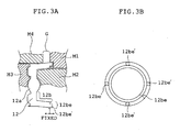
- a gate G that is used for injection molding of the lens element 12 is arranged in the flange part 12b at a position near the image pickup element 20 so that a mark of the gate is near the image pickup element 20, the structure of various molding dies used for the injection molding of the lens element 12 may be as shown in Fig. 3A .
- the lens element 12 is surrounded by: a molding die M1 that forms an end part 12be of the flange part 12b and a touching part 12be' that touches the image pickup element 20; a molding die M2 that forms the inner side of the flange part 12b and the lens element part 12a; a molding die M3 that forms the object side of the flange part 12b and the lens element part 12a; and a molding die M4 that forms the outside of the flange part 12b.
- the part that forms the touching part 12be' is made short in the axial direction by satisfying Condition (1) above, thereby enabling a channel of the melted resin from the gate G to be minimized in length.
- Fig. 3B is a view of the lens element having a flange part that is integral with the lens element as viewed in the axial direction from the side that faces the image pickup element (in the case where the lens element is mounted so as to abut the image pickup element) . As can be seen, there are multiple touching parts 12be' spaced near the outer perimeter of the end part 12be.
- the flange part 12b becomes long in the axial direction, and accordingly, an effect of miniaturizing the outer diameter of the entire image pickup module (due to the tapering formed in the outside perimeter portion 12bo) can be more easily obtained.
- the image pickup module of the present invention includes an image forming lens 10 and an image pickup element 20.
- item 30 is an aperture stop.
- the image forming lens 10 includes two or more lens elements 11 and 12, in order from the object side, as well as a frame 13.
- the lens element 12 is manufactured by injection molding, and includes a flange part 12b that is integrally formed with a lens part 12a.
- G is a gate position used at the time of the injection molding.
- a gate G is arranged in the flange part 12b at a position which is near the image pickup element 20, and a mark of the gate (the mark is not shown) remains in a corresponding part of the flange part 12b.
- the lens element 12 is injection molded so that the outside-perimeter-part 12bo of the flange part 12b has an inclination such that the diameter thereof becomes larger as successive measurements are taken nearer to the image pickup element 20 side.
- the lens element 11 is formed with an outer diameter smaller than any outer diameter of the lens element 12.
- the frame 13 is manufactured of a light-blocking material. Moreover, the frame 13 holds all or a predetermined part of the outside perimeter portion of each lens element that is included in the image forming lens, and is arranged so as to cover at least a part of the outside perimeter portion of the lens elements 11 and 12.
- any outside perimeter portion of the lens elements 11 and 12 not covered by the frame 13 will have a light-blocking material applied thereto, such as a light-blocking adhesive.
- the outside perimeter portion 13o of the frame 13 includes inclined part 13o1 that is inclined so that the diameter thereof becomes larger when successively measured at positions nearer the image pickup element 20.
- the inner circumference portion 13i of the frame 13 has an inclined part 13il that is inclined so that its diameter also becomes larger when successively measured at positions nearer the image pickup element 20.
- an inner circumference portion of the frame has an inclined part on the image pickup element side that is inclined so that its diameter increases when successively measured nearer the image pickup element side, with the inclination amount being different than the inclination amount of the outside perimeter portion of the lens element having a flange part at a region nearest the image pickup element.
- the difference in inclinations is such that a small clearance that forms, between the inner circumference portion of the frame and the outside perimeter portion of the flange part, when the image pickup module is assembled, increases when successively measured at positions nearer to the image pickup element side.
- the outer diameter of the image pickup module having the lens element 12 with the flange part 12b can be miniaturized on the object side of the image pickup module, thereby allowing space for arranging a light source, such as an LED, that is secured to the object side of the image pickup module.
- a light source such as an LED
- the outside-perimeter-part of the lens element 12 is arranged to have an inclination so that its diameter becomes smaller when successively measured nearer the object side, (i.e., it becomes larger when successively measured nearer to the side of the image pickup element 20), and the inner circumference portion 13i of the frame 13, is formed with an inclined part 13il that is inclined so that its diameter becomes smaller when successively measured nearer the object side, (i.e., the inner circumference increases when successively measured nearer to the image pickup element 20).
- the two inclinations are different so that, when assembled, a small clearance between the outside perimeter portion 12bo of the flange part 12b and the frame becomes larger nearer the image pickup element 20.
- the outer diameter of the entirety of the image pickup module having the lens element 12 with the flange part 12b can be miniaturized, thereby allowing a space for a light source, such as an LED, to be secured to the object side of the image pickup module without enlarging the module as a whole, as required in the prior art. Satisfying Condition (2) above assists in insuring that a sufficient space for a light source, such as the LED, is provided.
- the miniaturization effect of the image pickup module according to the present invention becomes remarkable when it is used for optical devices for which miniaturization is greatly demanded, such as a capsule endoscope or even a common endoscope.
- Figs. 4A and 4B show axial and sectional views, respectively, of a capsule endoscope that includes the image pickup module according to Embodiment 1 of the present invention, with Fig. 4A being an axial view of the capsule endoscope as seen from the object side, and with Fig. 4B being a sectional view along the lines A-A shown in Fig. 4A .
- the capsule endoscope of Figs. 4A and 4B includes a transparent cover 41 and two or more lighting components 42 (that, for example, may be formed of LEDs), and an image pickup module.
- the transparent cover 41 is arranged at the tip of the housing for the main part of the endoscope 43.
- the fundamental composition of the image pickup module is the same as shown in Fig. 1 .
- item 21 is a cover glass that covers the image pickup surface of the image pickup element.
- a substrate part 44 is arranged inside the tip of the housing for the main part of the endoscope 43.
- the image pickup module is attached to the central part of the substrate part 44, and further, the lighting components 42 are arranged annularly and attached between the image pickup module and the housing for the main part of the endoscope 43 in the substrate part 44.
- the thickness t1 is 1 mm
- the distance t 2 is 1.3 mm
- the ratio t2/t1 equals 1.3.
- Condition (1) is satisfied by this embodiment.
- the taper angle A is 10 degrees
- the taper angle B is 5 degrees
- the ratio A/B equals 2. Therefore, Condition (2) is satisfied by this embodiment.
- Figs. 5A and 5B show axial and sectional views, respectively, of a capsule endoscope that includes the image pickup module according to Embodiment 2 of the present invention, with Fig. 5A being an axial view of the capsule endoscope as seen from the object side, and with Fig. 5B being a sectional view along the lines A-A shown in Fig. 5A .
- the fundamental constitution of the image pickup module is the same as for Embodiment 2 shown in Fig. 2 .
- This Embodiment is similar to that of Embodiment 1, so that both Condition (1) and Condition (2) above are satisfied by this embodiment.
- Fig. 6 is a sectional view showing an image pickup module according to Embodiment 3 of the present invention for use in a capsule endoscope.
- the fundamental composition of the image pickup module is the same as the image pickup module of Embodiment 1 shown in Fig. 1 .
- the thickness t1 is 1.15 mm
- the distance t 2 is 1.15 mm
- the ratio t2/t1 equals 1.0
- the taper angle A is 6 degrees
- the taper angle B is 4 degrees
- the ratio A/B equals 1.5. Therefore, both Condition (1) and Condition (2) above are satisfied by this embodiment.
- Fig. 7 is a sectional view showing an image pickup module according to Embodiment 4 of the present invention for use in a capsule endoscope.
- the fundamental composition of the image pickup module is the same as for Embodiment 2 shown in Fig. 2 .
- the thickness t1 is 0.8 mm
- the distance t 2 is 0.65 mm
- the value of t2/t1 equals 0.8125
- the taper angle A is 9 degrees
- the taper angle B is 3 degrees
- the ratio A/B equals 3.0. Therefore, both Condition (1) and Condition (2) above are satisfied by this embodiment.
- the lighting component(s) thereof are generally arranged around the image pickup module.
- the lighting components since lighting components often have been standardized, arbitrary miniaturization of these components is difficult.
- the decrease in burden to a patient by miniaturization can be very significant even though the actual amount of miniaturization is rather small.
- the diameter of the entire image pickup module can be miniaturized. This enables the entire capsule endoscope diameter to be miniaturized, while still providing sufficient space for lighting components to be arranged near the periphery of the image pickup module.
- the touching part 12be' of the flange part 12b of the lens element 12 can be formed with a high degree of accuracy, and the positioning of the lens element 12 relative to the image pickup element 20 can be achieved with a high degree of accuracy at the time of manufacturing the image pickup module.
- the image forming lens 10 is not limited to being formed of only two lens elements, such as by using lens elements 11 and 12 discussed above, as it may also be formed using three or more lens elements.
- the lens element nearest to the image pickup element should be formed integral with a flange part, just as the lens element 12 is formed in the embodiments mentioned above.
- the image pickup module according to the present invention is useful in any field wherein an observation device is required that is equipped with a small image pickup element, and for which miniaturization and high accuracy positioning are necessary. Such variations are not to be regarded as a departure from the scope of the invention. Rather, the scope of the invention shall be defined as set forth in the following claims.
Landscapes
- Engineering & Computer Science (AREA)
- Multimedia (AREA)
- Signal Processing (AREA)
- Health & Medical Sciences (AREA)
- Physics & Mathematics (AREA)
- Life Sciences & Earth Sciences (AREA)
- Surgery (AREA)
- Optics & Photonics (AREA)
- Medical Informatics (AREA)
- Animal Behavior & Ethology (AREA)
- Pathology (AREA)
- Radiology & Medical Imaging (AREA)
- General Physics & Mathematics (AREA)
- Biomedical Technology (AREA)
- Nuclear Medicine, Radiotherapy & Molecular Imaging (AREA)
- Heart & Thoracic Surgery (AREA)
- Molecular Biology (AREA)
- Biophysics (AREA)
- General Health & Medical Sciences (AREA)
- Public Health (AREA)
- Veterinary Medicine (AREA)
- Endoscopes (AREA)
- Studio Devices (AREA)
- Lens Barrels (AREA)
Claims (9)
- Bildaufnahmemodul, umfassend:eine Bildgabelinse (10), die ein Linsenelement (12) umfasst, das einen Linsenabschnitt (12a) und einen Flanschabschnitt (12b) aufweist, die beide einstückig mit dem Linsenelement sind, wobei der Flanschabschnitt einen Endabschnitt (12be) umfasst, und wobei der Endabschnitt eine Mehrzahl von Berührabschnitten (12be') umfasst, die nahe dem Außenperimeter des Endabschnitts beabstandet sind; undein Bildaufnahmeelement (20), das angeordnet ist, um Licht von der Bildgabelinse zu empfangen, wobei das Linsenelement angebracht ist, um gegen das Bildaufnahmeelement zu stoßen, wobei die Mehrzahl von Berührabschnitten das Bildaufnahmeelement berührt;wobei:ein äußerer Perimeterabschnitt (12bo) des Linsenelements, das den Flanschabschnitt aufweist, bei einem dem Bildaufnahmeelement nächstgelegenen Bereich derart geneigt ist, dass äußere Durchmesser des Linsenelements, das den Flanschabschnitt aufweist, sich in dem Bereich erhöhen, wenn bei Positionen sukzessive näher dem Bildaufnahmeelement gemessen,
dadurch gekennzeichnet, dass:die Bildgabelinse einen Rahmen (13) aufweist, der konfiguriert ist, um das Linsenelement oder Linsenelemente der Bildgabelinse zu halten,ein äußerer Perimeterabschnitt (13o) des Rahmens einen geneigten Abschnitt (13o1) auf der Objektseite des Rahmens aufweist, der derart geneigt ist, dass sich sein Durchmesser erhöht, wenn bei Positionen sukzessive näher der Bildaufnahmeelementseite gemessen undein innerer Umfangsabschnitt (13i) des Rahmens einen geneigten Abschnitt (13i1) auf der Bildaufnahmeelementseite aufweist, der derart geneigt ist, dass sich sein Durchmesser erhöht, wenn sukzessive näher der Bildaufnahmeelementseite gemessen, wobei der Neigungsbetrag von dem Neigungsbetrag des äußeren Perimeterabschnitts des Linsenelements verschieden ist, das den Flanschabschnitt aufweist, bei einem dem Bildaufnahmeelement nächstgelegenen Bereich, so dass eine kleine Aussparung zwischen dem inneren Umfangsabschnitt des Rahmens und dem äußeren Perimeterabschnitt des Flanschabschnitts ausgebildet wird und die kleine Aussparung zunimmt, wenn bei Positionen sukzessive näher der Bildaufnahmeelementseite gemessen. - Bildaufnahmemodul gemäß Anspruch 1, dadurch gekennzeichnet, dass:das Linsenelement, das den Flanschabschnitt aufweist, durch Spritzgießen hergestellt wird, wobei sich eine Markierung eines Durchlasses (G), der in dem Spritzgießvorgang verwendet wird, nahe dem Bildaufnahmeelement befindlich ist.
- Bildaufnahmemodul gemäß Anspruch 1 oder 2, dadurch gekennzeichnet, dass:die Bildgabelinse zwei oder mehr Elemente (11, 12) umfasst, die in Reihenfolge von der Objektseite angeordnet sind; undein Außendurchmesser des Linsenelements, das der Objektseite nächstgelegen positioniert ist, kleiner als irgendein Außendurchmesser des Linsenelements ist, das den Flanschabschnitt aufweist.
- Bildaufnahmemodul gemäß Anspruch 1, dadurch gekennzeichnet, dass der Rahmen aus einem lichtblockierenden Material ausgebildet ist und angeordnet ist, um den äußeren Perimeterabschnitt des Linsenelements oder der Elemente, das oder die die Bildgabelinse bildet oder bilden, beinahe zur Gänze zu bedecken.
- Bildaufnahmemodul gemäß Anspruch 1, dadurch gekennzeichnet, dass der Rahmen aus einem lichtblockierenden Material ausgebildet ist und angeordnet ist, um einen Teil des äußeren Perimeterabschnitts des Linsenelements oder der Elemente abzudecken, das oder die die Bildgabelinse bildet oder bilden, und eine Lichtblockierkomponente bei einem Teil angeordnet ist, der nicht durch den Rahmen in dem äußeren Perimeterabschnitt des Linsenelements oder der Elemente der Bildgabelinse abgedeckt ist.
- Bildaufnahmemodul gemäß Anspruch 5, dadurch gekennzeichnet, dass die Lichtblockierkomponenten ein Klebemittel sind, das schwarze Farbe beinhaltet.
- Bildaufnahmemodul gemäß zumindest einem der Ansprüche 1 bis 6, dadurch gekennzeichnet, dass
das Bildaufnahmemodul zur Verwendung in einem Endoskop ausgelegt ist. - Bildaufnahmemodul gemäß Anspruch 1, dadurch gekennzeichnet, dass die nachfolgende Bedingung erfüllt wird:

wobei
t1 die Dicke des Zentrums des optischen Abschnitts des Linsenelements ist, der dem Bildaufnahmeelement nächstgelegen ist, und
t2 der Abstand von der Bildseitenoberfläche des Zentrumsabschnitts des optischen Abschnitts des Linsenelements, der dem Bildaufnahmeelement nächstgelegen ist, zu dem Bildaufnahmeelement ist. - Bildaufnahmemodul gemäß Anspruch 1, dadurch gekennzeichnet, dass die nachfolgende Bedingung erfüllt wird:

wobei
A der Neigungswinkel des inneren Umfangsabschnitts des Rahmens ist, und
B der Neigungswinkel des äußeren Perimeterabschnitts eines Linsenelements der Bildgabelinse des Bildaufnahmemoduls ist.
Applications Claiming Priority (1)
| Application Number | Priority Date | Filing Date | Title |
|---|---|---|---|
| JP2006311283A JP4339883B2 (ja) | 2006-11-17 | 2006-11-17 | 撮像モジュール及び撮像モジュール用結像レンズ、並びに、撮像モジュールを用いた内視鏡 |
Publications (2)
| Publication Number | Publication Date |
|---|---|
| EP1923728A1 EP1923728A1 (de) | 2008-05-21 |
| EP1923728B1 true EP1923728B1 (de) | 2013-04-17 |
Family
ID=39186105
Family Applications (1)
| Application Number | Title | Priority Date | Filing Date |
|---|---|---|---|
| EP07022024.9A Not-in-force EP1923728B1 (de) | 2006-11-17 | 2007-11-13 | Bilderfassungsmodul und Bildformungslinse dafür |
Country Status (5)
| Country | Link |
|---|---|
| US (1) | US8355216B2 (de) |
| EP (1) | EP1923728B1 (de) |
| JP (1) | JP4339883B2 (de) |
| KR (1) | KR101409523B1 (de) |
| CN (1) | CN101183169B (de) |
Families Citing this family (23)
| Publication number | Priority date | Publication date | Assignee | Title |
|---|---|---|---|---|
| JP5047243B2 (ja) | 2008-09-26 | 2012-10-10 | シャープ株式会社 | 光学素子ウエハモジュール、光学素子モジュール、光学素子モジュールの製造方法、電子素子ウエハモジュール、電子素子モジュールの製造方法、電子素子モジュールおよび電子情報機器 |
| CN101726821B (zh) * | 2008-10-30 | 2011-03-23 | 鸿富锦精密工业(深圳)有限公司 | 透镜组 |
| WO2011021450A1 (ja) * | 2009-08-19 | 2011-02-24 | オリンパスメディカルシステムズ株式会社 | レンズユニット及びそれを備えたカプセル内視鏡 |
| TWM372050U (en) * | 2009-09-09 | 2010-01-01 | Azurewave Technologies Inc | Image capturing module capable of simplifying optical component |
| CN102033285A (zh) * | 2009-09-29 | 2011-04-27 | 鸿富锦精密工业(深圳)有限公司 | 镜头模组 |
| JP5874007B2 (ja) * | 2011-08-25 | 2016-03-01 | パナソニックIpマネジメント株式会社 | レンズ鏡筒 |
| JP6000654B2 (ja) * | 2012-05-29 | 2016-10-05 | シャープ株式会社 | レンズ、レンズユニット、およびレンズアレイ |
| JP6373268B2 (ja) * | 2013-08-20 | 2018-08-15 | 株式会社ダイセル | ウェハレンズ、ウェハレンズアレイ、ウェハレンズ積層体、及びウェハレンズアレイ積層体 |
| CN103676065B (zh) * | 2013-10-31 | 2016-01-06 | 中国科学院上海光学精密机械研究所 | 大口径透镜的调整固定装置 |
| US9829698B2 (en) * | 2015-08-31 | 2017-11-28 | Panasonic Corporation | Endoscope |
| DE102015013589B4 (de) * | 2015-10-21 | 2021-10-21 | Schölly Fiberoptic GmbH | Optische Anordnung und Endoskop |
| DE102015013588B4 (de) * | 2015-10-21 | 2021-09-16 | Schölly Fiberoptic GmbH | Optische Anordnung und Diagnostikeinrichtung |
| CN205507179U (zh) * | 2015-11-17 | 2016-08-24 | 瑞声声学科技(深圳)有限公司 | 镜头模组 |
| CN205210390U (zh) * | 2015-11-17 | 2016-05-04 | 瑞声声学科技(苏州)有限公司 | 镜头模组 |
| TWI625563B (zh) * | 2017-03-23 | 2018-06-01 | 大立光電股份有限公司 | 塑膠鏡筒、相機模組及電子裝置 |
| CN110837165A (zh) * | 2018-08-16 | 2020-02-25 | 宁波舜宇车载光学技术有限公司 | 光学镜头及其组装方法 |
| TWI761576B (zh) * | 2018-08-16 | 2022-04-21 | 先進光電科技股份有限公司 | 光學成像模組、成像系統及其製造方法 |
| CN209525505U (zh) * | 2018-11-19 | 2019-10-22 | 瑞声科技(新加坡)有限公司 | 玻璃镜片及使用该玻璃镜片的镜头模组 |
| TWI692400B (zh) * | 2018-12-14 | 2020-05-01 | 大立光電股份有限公司 | 光學鏡頭及電子裝置 |
| JP7105451B2 (ja) * | 2020-01-21 | 2022-07-25 | 株式会社精工技研 | レンズユニット |
| TWI702431B (zh) * | 2020-02-12 | 2020-08-21 | 大立光電股份有限公司 | 成像鏡頭、相機模組與電子裝置 |
| JP7595478B2 (ja) * | 2021-02-11 | 2024-12-06 | シチズンファインデバイス株式会社 | 接合体の製造方法 |
| US12329354B2 (en) * | 2022-02-02 | 2025-06-17 | Canon U.S.A, Inc. | Antitwist mechanism for robotic endoscope camera |
Citations (2)
| Publication number | Priority date | Publication date | Assignee | Title |
|---|---|---|---|---|
| US20040215059A1 (en) * | 2003-04-25 | 2004-10-28 | Olympus Corporation | Capsule endoscope apparatus |
| JP2005000320A (ja) * | 2003-06-10 | 2005-01-06 | Olympus Corp | カプセル型内視鏡 |
Family Cites Families (16)
| Publication number | Priority date | Publication date | Assignee | Title |
|---|---|---|---|---|
| US5359190A (en) | 1992-12-31 | 1994-10-25 | Apple Computer, Inc. | Method and apparatus for coupling an optical lens to an imaging electronics array |
| JP3365843B2 (ja) | 1993-12-08 | 2003-01-14 | オリンパス光学工業株式会社 | レンズ保持装置 |
| JPH1114804A (ja) | 1997-06-27 | 1999-01-22 | Fuji Photo Optical Co Ltd | プラスチックレンズ |
| JP2000147392A (ja) * | 1998-11-18 | 2000-05-26 | Nippon Sheet Glass Co Ltd | 内視鏡用対物レンズ |
| JP2002118776A (ja) | 2000-10-10 | 2002-04-19 | Konica Corp | 撮像装置 |
| TW523924B (en) * | 2001-01-12 | 2003-03-11 | Konishiroku Photo Ind | Image pickup device and image pickup lens |
| JP4446327B2 (ja) | 2001-01-12 | 2010-04-07 | コニカミノルタホールディングス株式会社 | 撮像装置及び撮像装置の組立方法 |
| JP2002350608A (ja) | 2001-05-23 | 2002-12-04 | Konica Corp | 撮像レンズ、撮像装置、金型及び撮像レンズの成形方法 |
| JP4751533B2 (ja) | 2001-07-16 | 2011-08-17 | オリンパス株式会社 | 顕微鏡用液浸レンズ |
| JP4300811B2 (ja) | 2003-02-03 | 2009-07-22 | コニカミノルタホールディングス株式会社 | 撮像装置及び携帯端末 |
| JP4110988B2 (ja) | 2003-02-03 | 2008-07-02 | コニカミノルタホールディングス株式会社 | 撮像装置及び携帯端末 |
| FR2854496B1 (fr) | 2003-04-29 | 2005-09-16 | St Microelectronics Sa | Boitier semi-conducteur |
| JP2005157290A (ja) | 2003-10-30 | 2005-06-16 | Hitachi Maxell Ltd | カメラ |
| JP2005345919A (ja) | 2004-06-04 | 2005-12-15 | Seiko Precision Inc | 撮像レンズ |
| JP2006084621A (ja) | 2004-09-15 | 2006-03-30 | Matsushita Electric Ind Co Ltd | レンズ位置決め方法およびそれを用いた光学装置 |
| JP4308233B2 (ja) * | 2006-09-01 | 2009-08-05 | オリンパスメディカルシステムズ株式会社 | 内視鏡用撮像モジュール |
-
2006
- 2006-11-17 JP JP2006311283A patent/JP4339883B2/ja not_active Expired - Fee Related
-
2007
- 2007-07-10 CN CN2007101284301A patent/CN101183169B/zh not_active Expired - Fee Related
- 2007-11-13 US US11/939,007 patent/US8355216B2/en not_active Expired - Fee Related
- 2007-11-13 EP EP07022024.9A patent/EP1923728B1/de not_active Not-in-force
- 2007-11-16 KR KR1020070117085A patent/KR101409523B1/ko not_active Expired - Fee Related
Patent Citations (2)
| Publication number | Priority date | Publication date | Assignee | Title |
|---|---|---|---|---|
| US20040215059A1 (en) * | 2003-04-25 | 2004-10-28 | Olympus Corporation | Capsule endoscope apparatus |
| JP2005000320A (ja) * | 2003-06-10 | 2005-01-06 | Olympus Corp | カプセル型内視鏡 |
Also Published As
| Publication number | Publication date |
|---|---|
| US20080117292A1 (en) | 2008-05-22 |
| EP1923728A1 (de) | 2008-05-21 |
| KR20080045065A (ko) | 2008-05-22 |
| US8355216B2 (en) | 2013-01-15 |
| JP4339883B2 (ja) | 2009-10-07 |
| CN101183169B (zh) | 2013-02-27 |
| KR101409523B1 (ko) | 2014-06-19 |
| CN101183169A (zh) | 2008-05-21 |
| JP2008129133A (ja) | 2008-06-05 |
Similar Documents
| Publication | Publication Date | Title |
|---|---|---|
| US8355216B2 (en) | Image pickup module and image forming lens for the same | |
| US7009654B2 (en) | Image pickup apparatus | |
| US7738180B2 (en) | Objective optical system for endoscopes | |
| CN101133934B (zh) | 内窥镜用摄像组件 | |
| JP5040412B2 (ja) | 撮像素子パッケージ、撮像素子モジュールおよびレンズ鏡筒並びに撮像装置 | |
| US20070097249A1 (en) | Camera module | |
| US20110096213A1 (en) | Wafer-shaped optical apparatus and manufacturing method thereof, electronic element wafer module, sensor wafer module, electronic element module,sensor module, and electronic information device | |
| EP3553581B1 (de) | Linsenstruktur, herstellungsverfahren dafür und kamera | |
| JP2009157279A (ja) | レンズユニット、撮像装置、電子機器、及びレンズユニットの組立方法 | |
| US20110298075A1 (en) | Lens Unit, Aligning Method, Image Pickup Device and Method for Manufacturing Image Pickup Device | |
| JP4248586B2 (ja) | 撮像装置及びその製造方法、並びに該撮像装置を搭載した携帯情報端末及び撮像機器 | |
| WO2016009972A1 (ja) | 固体撮像装置及びその製造方法 | |
| KR20110006616A (ko) | 촬상 렌즈, 촬상 모듈, 촬상 렌즈의 제조 방법, 및 촬상 모듈의 제조 방법 | |
| US20050271375A1 (en) | Imaging apparatus | |
| US20160062071A1 (en) | Lens barrel, optical apparatus, and method of manufacturing the lens barrel | |
| JP2004246258A (ja) | 撮影レンズ及び該撮影レンズを用いた光学機器 | |
| EP1720340A1 (de) | Kameramodul | |
| JP6967424B2 (ja) | 撮像装置 | |
| TWI801154B (zh) | 成像鏡頭、相機模組與電子裝置 | |
| US12379567B2 (en) | Lens unit | |
| JP2011070016A (ja) | レンズモジュール、撮影装置、レンズモジュールの製造方法 | |
| JP5083101B2 (ja) | 撮像素子ユニット、撮像素子モジュールおよびレンズ鏡筒並びに撮像装置 | |
| US6130787A (en) | Optical system and optical module | |
| KR20140054967A (ko) | 카메라 모듈 | |
| JP2011232614A (ja) | 撮像レンズの製造方法 |
Legal Events
| Date | Code | Title | Description |
|---|---|---|---|
| PUAI | Public reference made under article 153(3) epc to a published international application that has entered the european phase |
Free format text: ORIGINAL CODE: 0009012 |
|
| AK | Designated contracting states |
Kind code of ref document: A1 Designated state(s): AT BE BG CH CY CZ DE DK EE ES FI FR GB GR HU IE IS IT LI LT LU LV MC MT NL PL PT RO SE SI SK TR |
|
| AX | Request for extension of the european patent |
Extension state: AL BA HR MK RS |
|
| 17P | Request for examination filed |
Effective date: 20081117 |
|
| AKX | Designation fees paid |
Designated state(s): DE FR GB |
|
| 17Q | First examination report despatched |
Effective date: 20100517 |
|
| GRAP | Despatch of communication of intention to grant a patent |
Free format text: ORIGINAL CODE: EPIDOSNIGR1 |
|
| GRAS | Grant fee paid |
Free format text: ORIGINAL CODE: EPIDOSNIGR3 |
|
| GRAA | (expected) grant |
Free format text: ORIGINAL CODE: 0009210 |
|
| AK | Designated contracting states |
Kind code of ref document: B1 Designated state(s): DE FR GB |
|
| REG | Reference to a national code |
Ref country code: GB Ref legal event code: FG4D |
|
| REG | Reference to a national code |
Ref country code: DE Ref legal event code: R096 Ref document number: 602007029774 Country of ref document: DE Effective date: 20130613 |
|
| PLBE | No opposition filed within time limit |
Free format text: ORIGINAL CODE: 0009261 |
|
| STAA | Information on the status of an ep patent application or granted ep patent |
Free format text: STATUS: NO OPPOSITION FILED WITHIN TIME LIMIT |
|
| 26N | No opposition filed |
Effective date: 20140120 |
|
| REG | Reference to a national code |
Ref country code: DE Ref legal event code: R097 Ref document number: 602007029774 Country of ref document: DE Effective date: 20140120 |
|
| GBPC | Gb: european patent ceased through non-payment of renewal fee |
Effective date: 20131113 |
|
| REG | Reference to a national code |
Ref country code: FR Ref legal event code: ST Effective date: 20140731 |
|
| PG25 | Lapsed in a contracting state [announced via postgrant information from national office to epo] |
Ref country code: GB Free format text: LAPSE BECAUSE OF NON-PAYMENT OF DUE FEES Effective date: 20131113 Ref country code: FR Free format text: LAPSE BECAUSE OF NON-PAYMENT OF DUE FEES Effective date: 20131202 |
|
| REG | Reference to a national code |
Ref country code: DE Ref legal event code: R082 Ref document number: 602007029774 Country of ref document: DE Representative=s name: WUESTHOFF & WUESTHOFF, PATENTANWAELTE PARTG MB, DE Ref country code: DE Ref legal event code: R081 Ref document number: 602007029774 Country of ref document: DE Owner name: OLYMPUS CORPORATION, JP Free format text: FORMER OWNER: OLYMPUS MEDICAL SYSTEMS CORP., TOKYO, JP |
|
| PGFP | Annual fee paid to national office [announced via postgrant information from national office to epo] |
Ref country code: DE Payment date: 20181120 Year of fee payment: 12 |
|
| REG | Reference to a national code |
Ref country code: DE Ref legal event code: R119 Ref document number: 602007029774 Country of ref document: DE |
|
| PG25 | Lapsed in a contracting state [announced via postgrant information from national office to epo] |
Ref country code: DE Free format text: LAPSE BECAUSE OF NON-PAYMENT OF DUE FEES Effective date: 20200603 |