EP1923854A2 - Plasmaanzeige und Verfahren zu ihrer Ansteuerung - Google Patents
Plasmaanzeige und Verfahren zu ihrer Ansteuerung Download PDFInfo
- Publication number
- EP1923854A2 EP1923854A2 EP07109919A EP07109919A EP1923854A2 EP 1923854 A2 EP1923854 A2 EP 1923854A2 EP 07109919 A EP07109919 A EP 07109919A EP 07109919 A EP07109919 A EP 07109919A EP 1923854 A2 EP1923854 A2 EP 1923854A2
- Authority
- EP
- European Patent Office
- Prior art keywords
- subfield
- subfields
- group
- frame
- weight value
- Prior art date
- Legal status (The legal status is an assumption and is not a legal conclusion. Google has not performed a legal analysis and makes no representation as to the accuracy of the status listed.)
- Withdrawn
Links
Images



Classifications
-
- G—PHYSICS
- G09—EDUCATION; CRYPTOGRAPHY; DISPLAY; ADVERTISING; SEALS
- G09G—ARRANGEMENTS OR CIRCUITS FOR CONTROL OF INDICATING DEVICES USING STATIC MEANS TO PRESENT VARIABLE INFORMATION
- G09G3/00—Control arrangements or circuits, of interest only in connection with visual indicators other than cathode-ray tubes
- G09G3/20—Control arrangements or circuits, of interest only in connection with visual indicators other than cathode-ray tubes for presentation of an assembly of a number of characters, e.g. a page, by composing the assembly by combination of individual elements arranged in a matrix no fixed position being assigned to or needed to be assigned to the individual characters or partial characters
- G09G3/22—Control arrangements or circuits, of interest only in connection with visual indicators other than cathode-ray tubes for presentation of an assembly of a number of characters, e.g. a page, by composing the assembly by combination of individual elements arranged in a matrix no fixed position being assigned to or needed to be assigned to the individual characters or partial characters using controlled light sources
- G09G3/28—Control arrangements or circuits, of interest only in connection with visual indicators other than cathode-ray tubes for presentation of an assembly of a number of characters, e.g. a page, by composing the assembly by combination of individual elements arranged in a matrix no fixed position being assigned to or needed to be assigned to the individual characters or partial characters using controlled light sources using luminous gas-discharge panels, e.g. plasma panels
- G09G3/288—Control arrangements or circuits, of interest only in connection with visual indicators other than cathode-ray tubes for presentation of an assembly of a number of characters, e.g. a page, by composing the assembly by combination of individual elements arranged in a matrix no fixed position being assigned to or needed to be assigned to the individual characters or partial characters using controlled light sources using luminous gas-discharge panels, e.g. plasma panels using AC panels
-
- G—PHYSICS
- G09—EDUCATION; CRYPTOGRAPHY; DISPLAY; ADVERTISING; SEALS
- G09G—ARRANGEMENTS OR CIRCUITS FOR CONTROL OF INDICATING DEVICES USING STATIC MEANS TO PRESENT VARIABLE INFORMATION
- G09G3/00—Control arrangements or circuits, of interest only in connection with visual indicators other than cathode-ray tubes
- G09G3/20—Control arrangements or circuits, of interest only in connection with visual indicators other than cathode-ray tubes for presentation of an assembly of a number of characters, e.g. a page, by composing the assembly by combination of individual elements arranged in a matrix no fixed position being assigned to or needed to be assigned to the individual characters or partial characters
- G09G3/22—Control arrangements or circuits, of interest only in connection with visual indicators other than cathode-ray tubes for presentation of an assembly of a number of characters, e.g. a page, by composing the assembly by combination of individual elements arranged in a matrix no fixed position being assigned to or needed to be assigned to the individual characters or partial characters using controlled light sources
- G09G3/28—Control arrangements or circuits, of interest only in connection with visual indicators other than cathode-ray tubes for presentation of an assembly of a number of characters, e.g. a page, by composing the assembly by combination of individual elements arranged in a matrix no fixed position being assigned to or needed to be assigned to the individual characters or partial characters using controlled light sources using luminous gas-discharge panels, e.g. plasma panels
- G09G3/288—Control arrangements or circuits, of interest only in connection with visual indicators other than cathode-ray tubes for presentation of an assembly of a number of characters, e.g. a page, by composing the assembly by combination of individual elements arranged in a matrix no fixed position being assigned to or needed to be assigned to the individual characters or partial characters using controlled light sources using luminous gas-discharge panels, e.g. plasma panels using AC panels
- G09G3/291—Control arrangements or circuits, of interest only in connection with visual indicators other than cathode-ray tubes for presentation of an assembly of a number of characters, e.g. a page, by composing the assembly by combination of individual elements arranged in a matrix no fixed position being assigned to or needed to be assigned to the individual characters or partial characters using controlled light sources using luminous gas-discharge panels, e.g. plasma panels using AC panels controlling the gas discharge to control a cell condition, e.g. by means of specific pulse shapes
-
- G—PHYSICS
- G09—EDUCATION; CRYPTOGRAPHY; DISPLAY; ADVERTISING; SEALS
- G09G—ARRANGEMENTS OR CIRCUITS FOR CONTROL OF INDICATING DEVICES USING STATIC MEANS TO PRESENT VARIABLE INFORMATION
- G09G3/00—Control arrangements or circuits, of interest only in connection with visual indicators other than cathode-ray tubes
- G09G3/20—Control arrangements or circuits, of interest only in connection with visual indicators other than cathode-ray tubes for presentation of an assembly of a number of characters, e.g. a page, by composing the assembly by combination of individual elements arranged in a matrix no fixed position being assigned to or needed to be assigned to the individual characters or partial characters
- G09G3/22—Control arrangements or circuits, of interest only in connection with visual indicators other than cathode-ray tubes for presentation of an assembly of a number of characters, e.g. a page, by composing the assembly by combination of individual elements arranged in a matrix no fixed position being assigned to or needed to be assigned to the individual characters or partial characters using controlled light sources
- G09G3/28—Control arrangements or circuits, of interest only in connection with visual indicators other than cathode-ray tubes for presentation of an assembly of a number of characters, e.g. a page, by composing the assembly by combination of individual elements arranged in a matrix no fixed position being assigned to or needed to be assigned to the individual characters or partial characters using controlled light sources using luminous gas-discharge panels, e.g. plasma panels
- G09G3/288—Control arrangements or circuits, of interest only in connection with visual indicators other than cathode-ray tubes for presentation of an assembly of a number of characters, e.g. a page, by composing the assembly by combination of individual elements arranged in a matrix no fixed position being assigned to or needed to be assigned to the individual characters or partial characters using controlled light sources using luminous gas-discharge panels, e.g. plasma panels using AC panels
- G09G3/296—Driving circuits for producing the waveforms applied to the driving electrodes
-
- G—PHYSICS
- G09—EDUCATION; CRYPTOGRAPHY; DISPLAY; ADVERTISING; SEALS
- G09G—ARRANGEMENTS OR CIRCUITS FOR CONTROL OF INDICATING DEVICES USING STATIC MEANS TO PRESENT VARIABLE INFORMATION
- G09G2320/00—Control of display operating conditions
- G09G2320/02—Improving the quality of display appearance
- G09G2320/0247—Flicker reduction other than flicker reduction circuits used for single beam cathode-ray tubes
-
- G—PHYSICS
- G09—EDUCATION; CRYPTOGRAPHY; DISPLAY; ADVERTISING; SEALS
- G09G—ARRANGEMENTS OR CIRCUITS FOR CONTROL OF INDICATING DEVICES USING STATIC MEANS TO PRESENT VARIABLE INFORMATION
- G09G2320/00—Control of display operating conditions
- G09G2320/02—Improving the quality of display appearance
- G09G2320/0261—Improving the quality of display appearance in the context of movement of objects on the screen or movement of the observer relative to the screen
-
- G—PHYSICS
- G09—EDUCATION; CRYPTOGRAPHY; DISPLAY; ADVERTISING; SEALS
- G09G—ARRANGEMENTS OR CIRCUITS FOR CONTROL OF INDICATING DEVICES USING STATIC MEANS TO PRESENT VARIABLE INFORMATION
- G09G2360/00—Aspects of the architecture of display systems
- G09G2360/16—Calculation or use of calculated indices related to luminance levels in display data
-
- G—PHYSICS
- G09—EDUCATION; CRYPTOGRAPHY; DISPLAY; ADVERTISING; SEALS
- G09G—ARRANGEMENTS OR CIRCUITS FOR CONTROL OF INDICATING DEVICES USING STATIC MEANS TO PRESENT VARIABLE INFORMATION
- G09G3/00—Control arrangements or circuits, of interest only in connection with visual indicators other than cathode-ray tubes
- G09G3/20—Control arrangements or circuits, of interest only in connection with visual indicators other than cathode-ray tubes for presentation of an assembly of a number of characters, e.g. a page, by composing the assembly by combination of individual elements arranged in a matrix no fixed position being assigned to or needed to be assigned to the individual characters or partial characters
- G09G3/22—Control arrangements or circuits, of interest only in connection with visual indicators other than cathode-ray tubes for presentation of an assembly of a number of characters, e.g. a page, by composing the assembly by combination of individual elements arranged in a matrix no fixed position being assigned to or needed to be assigned to the individual characters or partial characters using controlled light sources
- G09G3/28—Control arrangements or circuits, of interest only in connection with visual indicators other than cathode-ray tubes for presentation of an assembly of a number of characters, e.g. a page, by composing the assembly by combination of individual elements arranged in a matrix no fixed position being assigned to or needed to be assigned to the individual characters or partial characters using controlled light sources using luminous gas-discharge panels, e.g. plasma panels
- G09G3/2803—Display of gradations
Definitions
- the present invention relates to a plasma display and a driving method thereof, and particularly to a plasma display for preventing flicker when an image is realized by receiving a phase alternating by line (PAL) video signal, and improving an image quality, and a driving method thereof.
- PAL phase alternating by line
- a plasma display is a flat panel display that uses plasma generated by gas discharge to display characters or images. It includes, depending on its size, more than several scores to millions of discharge cells (hereinafter, also referred to as "cells") arranged in a matrix pattern.
- a grayscale expression method for dividing one frame into a plurality of subfields and time-divisionally controlling the subfields is generally used.
- image displaying methods in the plasma display device are classified as a National Television System Committee (NTSC) method and a phase alternate line (PAL) method according to a vertical synchronization frequency.
- NTSC National Television System Committee
- PAL phase alternate line
- the time corresponding to one frame in the PAL method is longer than that of the NTSC method.
- a screen may seem to flicker. That is, a subfield perceived as the brightest one has the highest weight value, which is conventionally provided as a first subfield or a last subfield of the frame when the subfields are arranged. Accordingly, the user perceives that the screen seems to vary every 20ms, and the interval in this case may be sufficiently perceived by the user, so that a flicker effect for flickering the screen may be generated.
- the present invention has been made in an effort to provide a plasma display for reducing a flickering effect in a phase alternating by line (PAL) method, and a driving method thereof.
- a driving method of a plasma display for dividing one frame into a plurality of subfields respectively having weight values and grouping the plurality of subfields into at least two subfield groups, an automatic power control level for one frame is determined according to an externally input image signal, the plurality of subfields are grouped into time-sequential first, second, and third subfield groups when the automatic power control level for one frame is higher than a reference value, and the plurality of subfields are grouped into the first subfield group and a fourth subfield group when the automatic power control level for one frame is lower than the reference value.
- the number of subfields included in the fourth subfield group is the same as that of the third subfield group, and a sum of weight values of the plurality of subfields in the fourth subfield group is the same as that of the third subfield group.
- the weight value of a first subfield having the highest weight value among the plurality of subfields in the fourth subfield group corresponds to a sum of the weight values of a second subfield having the highest weight value among the plurality of subfields in the third subfield group and the weight values of the plurality of subfields in the second subfield group.
- a sum of the weight values of a first subfield having the highest weight value among the plurality of subfields in the fourth subfield group and a second subfield having the second highest weight value among the plurality of subfields in the fourth subfield group is greater than a sum of the weight values of a third subfield having the highest weight value among the plurality of subfields in the third subfield group and a fourth subfield having the second highest weight value next to the third subfield among the plurality of subfields in the third subfield group, by a sum of the weight values of the plurality of subfields in the second subfield group.
- the second subfield group includes a fifth subfield having the least weight value among the plurality of subfields divided from one frame.
- the second subfield group includes a sixth subfield having the second least weight value next to the fifth subfield among the first subfield and the plurality of subfields divided from one frame.
- the subfields are arranged from the subfield having the least weight value to the subfield having the highest weight value in the respective first to fourth subfield groups, and a sum of the weight values of the plurality of subfields in the first subfield group is the same as that of the plurality of subfields in the third subfield group.
- An exemplary plasma display includes a plasma display panel (PDP) and a controller.
- the controller drives the PDP while dividing one frame into a plurality of subfields, generates a control signal for grouping the plurality of subfields into at least two subfield groups, and determines an automatic power control level through an input image signal.
- the controller groups the plurality of subfields into a first subfield group having a first number of subfields, a second subfield group having a second number of subfields that is smaller than the first number, and a third subfield group having a third number of subfields that is greater than the second number when the automatic power control level corresponding to one frame is higher than a reference value, and groups the plurality of subfields into the first subfield group and a fourth subfield group having the third number of subfields when the automatic power control level corresponding to one frame is lower than the reference value.
- the controller establishes the second subfield group to include a first subfield having the least weight value among the plurality of subfields divided from one frame and a second subfield having the second least weight value next to the first subfield, and the controller establishes a sum of the weight values of the plurality of subfields in the fourth subfield group to be a sum of the weight values of the plurality of subfields in the second subfield and the weight values of the plurality of subfields in the third subfield group.
- the controller establishes the weight value of a first subfield having the highest weight value among the plurality of subfields in the fourth subfield group to be greater than the weight value of a second subfield having the highest weight value among the plurality of subfields in the first subfield group, and the controller establishes the weight value of a third subfield having the second highest weight value among the plurality of subfields in the fourth subfield group to be greater than the weight value of a fourth subfield having the second highest weight value among the plurality of subfields in the first subfield group.
- the controller determines a time corresponding to one frame according to a vertical synchronization frequency of a phase alternate line (PAL) method.
- PAL phase alternate line
- an automatic power control level for one frame is determined according to an externally input image signal, the plurality of subfields are grouped into time-sequential N groups when the automatic power control level for one frame is greater than a reference value, and the plurality of subfields are grouped into time-sequential M groups when the automatic power control level for one frame is less than the reference value.
- M is less than N.
- FIG. 1 is a schematic diagram of a plasma display according to an exemplary embodiment of the present invention.
- the plasma display includes a plasma display panel (PDP) 100, a controller 200, an address electrode driver 300, a scan electrode driver 400, and a sustain electrode driver 500.
- the PDP 100 includes a plurality of address electrodes A1 to Am extending in a column direction, and a plurality of sustain electrodes X1 to Xn and a plurality of scan electrodes Y1 to Yn extending in a row direction.
- the plurality of Y electrodes Y1 to Yn and X electrodes X1 to Xn are arranged in pairs.
- Discharge cells 12 are formed at intersections of adjacent Y electrodes Y1 to Yn and X electrodes X1 to Xn, and the A electrodes A1 to Am.
- the controller 200 divides one frame into a plurality of subfields respectively having weight values, and forms each subfield to have an address period and a sustain period.
- the controller 200 generates subfield data that indicate a non-light emitting state for the plurality of discharge cells 12 in the plurality of subfields, measures a screen load ratio from image data input for one frame, and determines a total number of sustain pulses applied to one frame according to the screen load ratio. In this case, the controller 200 applies the reduced number of sustain pulses when the screen load ratio is high to prevent power consumption from being increased. Further, the controller 200 determines the number of sustain pulses applied to each subfield according to a corresponding weight value.
- the controller 200 outputs an address electrode driving control signal, a sustain electrode driving control signal, and a scan electrode driving control signal according to the subfield data and the number of sustain pulses.
- the address electrode driver 300 receives the address electrode driving control signal from the controller 200 to apply a signal for selecting a displayed discharge cell to each of the A electrodes A1 to Am.
- the scan electrode driver 400 receives the scan electrode driving control signal from the controller 200 to apply a driving voltage to the Y electrodes Y1 to Yn
- the sustain electrode driver 500 receives the sustain electrode driving control signal from the controller 200 to apply the driving voltage to the X electrodes X1 to Xn.
- the plasma display for reducing the flickering effect in a phase alternating by line (PAL) method according to a first exemplary embodiment of the present invention, and a driving method thereof, will now be described.
- PAL phase alternating by line
- FIG. 2 is a diagram representing subfield arrangement in the PAL method according to the first exemplary embodiment of the present invention.
- one frame is divided into the plurality of subfields SF1 to SF14, the plurality of subfields are grouped into three subfield groups G1 to G3, and idle periods P1 to P3 are respectively formed after the respective subfield groups are finished.
- the subfields having relative higher weight values are dispersedly provided to the first subfield group G1 and the third subfield group G3. That is, as shown in FIG. 2, the first subfield group G1 includes the first subfield SF1, the second subfield SF2, the third subfield SF3, the fourth subfield SF4, the fifth subfield SF5, and the sixth subfield SF6 respectively having weight values of 4, 8, 16, 24, 32, and 40.
- the third subfield group G3 includes the ninth subfield SF9, the tenth subfield SF10, the eleventh subfield SF11, the twelfth subfield SF12, the thirteenth subfield SF13, and the fourteenth subfield SF14 respectively having the weight values of 4, 8, 16, 24, 32, and 40.
- an interval between light emitting axes by a starting point of the subfield group is within a vertical synchronization frequency range of 50Hz to 100Hz. Human eyes may not perceive the flickering effect with respect to a vertical frequency that is greater than 60Hz, and therefore the flickering effect may be reduced.
- the second subfield group G2 includes subfields having relatively lower weight values among the plurality of subfields divided from one frame. That is, as shown in FIG. 2, the second subfield group G2 includes the seventh subfield SF7 and the eighth subfield SF8 respectively having the weight values of 1 and 2. Accordingly, when expressing the low grayscale, a time difference between subfields that emit light in the cell may be reduced, and therefore a false contour at a boundary between the grayscales may be reduced when a low grayscale motion picture is expressed.
- each subfield group has a subfield configuration of a minimum increment arrangement, but it is not limited thereto, and another subfield configuration such as a minimum decrement arrangement may be applied in the first exemplary embodiment of the present invention.
- the flickering effect may be reduced.
- the false contour may be reduced.
- the controller calculates an automatic power control (APC) level during one frame from an external image, and determines the total number of sustain pulses applied to one frame according to the calculated APC level.
- APC automatic power control
- the APC level according to the exemplary embodiment of the present invention indicates power consumed while driving one frame, and the number of sustain pulses is adjusted according to the APC level to control power consumption.
- the APC level when the APC level is low, the number of sustain pulses applied to one frame is increased since the load is reduced. However, when the APC level is high, the number of sustain pulses applied to one frame is reduced since the load is increased.
- the number of sustain pulses applied to one frame is reduced since the APC level increases.
- the number of sustain pulses applied to one frame increases since the APC level decreases.
- the plurality of subfields divided from one frame are grouped into three subfield groups G1 to G3, a time corresponding to one subfield is reduced. Accordingly, since a time for applying the appropriate number of sustain pulses is lacking in the frame in which the low grayscale cells are largely included to have the low APC level, luminance may be deteriorated.
- a driving method of the plasma display for preventing the luminance deterioration in the PAL method when the APC level is low will now be described.
- FIG. 3 is a flowchart representing an operation of the controller 200 according to a second exemplary embodiment of the present invention
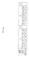
- FIG. 4A and FIG. 4B are diagrams representing subfield arrangement in the PAL method according to the second exemplary embodiment of the present invention.
- the controller 200 detects an average signal level (ASL) from R, G, and B data according to an externally input image signal.
- ASL may be given as Equation 1.
- R x,y , G x,y , and B x,y respectively denote R, G, and B grayscale values at a discharge cell of a position (x,y), and N and M respectively denote horizontal and vertical sizes of each frame.
- the controller 200 calculating the ASL as above determines the APC level from the ASL in step S310.
- controller 200 compares the APC level corresponding to one frame and a reference value in step S320.
- the plurality of subfields are grouped into three subfield groups G1 to G3 as shown in the subfield arrangement in FIG. 2.
- the controller 200 groups the plurality of subfields into two subfield groups G1 and G3' in step S340.
- the seventh subfield and the eighth subfield (not shown in FIG. 4A and FIG. 4B) in the second subfield group G2 are eliminated when the APC level is lower than the reference value, and the weight values of the seventh and eighth subfields are additionally provided to subfields having relatively higher weight values among the third subfield group G3'.
- the weight values of the subfields SF7 and SF8 in the second subfield group G2 are dispersedly provided to the fourteenth subfield SF14 and the thirteenth subfield SF13 having the highest weight values in the third subfield group G3', or as shown in FIG. 4B, they may be provided to the fourteenth subfield SF14.
- a sufficient time for applying the large number of sustain pulses is obtained since the subfield having the low weight value is eliminated when the APC level is low, and the luminance may be improved since the weight values of the eliminated subfields are dispersedly provided to both of the subfield having the highest weight value and the subfield having the second highest subfield or only to the subfield having the highest weight value.
- the reference value is an APC level value from which a time for applying the sustain pulse to the plurality of discharge cells starts to be insufficient during a time corresponding to one subfield since the number of sustain pulses applied to one subfield is large, which is well known to a person of an ordinary skill in the art and therefore detailed description thereof will be omitted.
- the subfield arrangement shown in FIG. 4A and FIG. 4B is only an example to describe the second exemplary embodiment of the present invention, and another subfield arrangement having another weight value configuration may be applied in the second exemplary embodiment of the present invention.
- the minimum increment arrangement is illustrated in FIG. 4A and FIG. 4B as the subfield arrangement, it is not limited thereto, and the minimum decrement arrangement may be applied according to the second exemplary embodiment of the present invention.
- the flickering effect may be reduced, and the luminance deterioration may be prevented.
Landscapes
- Engineering & Computer Science (AREA)
- Physics & Mathematics (AREA)
- Power Engineering (AREA)
- Plasma & Fusion (AREA)
- Computer Hardware Design (AREA)
- General Physics & Mathematics (AREA)
- Theoretical Computer Science (AREA)
- Control Of Indicators Other Than Cathode Ray Tubes (AREA)
- Control Of Gas Discharge Display Tubes (AREA)
Applications Claiming Priority (1)
| Application Number | Priority Date | Filing Date | Title |
|---|---|---|---|
| KR1020060112208A KR100908718B1 (ko) | 2006-11-14 | 2006-11-14 | 플라즈마 표시 장치 및 그 구동 방법 |
Publications (2)
| Publication Number | Publication Date |
|---|---|
| EP1923854A2 true EP1923854A2 (de) | 2008-05-21 |
| EP1923854A3 EP1923854A3 (de) | 2009-11-18 |
Family
ID=39032262
Family Applications (1)
| Application Number | Title | Priority Date | Filing Date |
|---|---|---|---|
| EP07109919A Withdrawn EP1923854A3 (de) | 2006-11-14 | 2007-06-08 | Plasmaanzeige und Verfahren zu ihrer Ansteuerung |
Country Status (2)
| Country | Link |
|---|---|
| EP (1) | EP1923854A3 (de) |
| KR (1) | KR100908718B1 (de) |
Cited By (1)
| Publication number | Priority date | Publication date | Assignee | Title |
|---|---|---|---|---|
| EP2159782A3 (de) * | 2008-08-29 | 2010-08-11 | Mitsubishi Electric Corporation | Gradationssteuerungsverfahren und Anzeigeverfahren |
Family Cites Families (7)
| Publication number | Priority date | Publication date | Assignee | Title |
|---|---|---|---|---|
| KR100467447B1 (ko) * | 2001-11-12 | 2005-01-24 | 삼성에스디아이 주식회사 | 플라즈마 디스플레이 패널의 화상 표시 방법 및 그 장치 |
| US7221335B2 (en) * | 2003-02-18 | 2007-05-22 | Samsung Sdi Co., Ltd | Image display method and device for plasma display panel |
| KR100570681B1 (ko) * | 2003-10-31 | 2006-04-12 | 삼성에스디아이 주식회사 | 플라즈마 디스플레이 패널의 화상 표시 방법 및 그 장치 |
| KR20050106697A (ko) * | 2004-05-06 | 2005-11-11 | 엘지전자 주식회사 | 플라즈마 디스플레이 패널의 구동방법 및 장치 |
| KR100521471B1 (ko) | 2004-05-28 | 2005-10-13 | 삼성에스디아이 주식회사 | 서브필드 위치 변동 방지를 위한 플라즈마 디스플레이패널의 구동 방법 및 그 장치 |
| KR101009451B1 (ko) * | 2004-07-24 | 2011-01-19 | 주식회사 대우일렉트로닉스 | 광학 센서를 이용한 pdp 텔레비전의 고화질 구현 장치 |
| KR100800526B1 (ko) * | 2005-11-18 | 2008-02-04 | 엘지전자 주식회사 | 플라즈마 디스플레이 장치 |
-
2006
- 2006-11-14 KR KR1020060112208A patent/KR100908718B1/ko not_active Expired - Fee Related
-
2007
- 2007-06-08 EP EP07109919A patent/EP1923854A3/de not_active Withdrawn
Cited By (1)
| Publication number | Priority date | Publication date | Assignee | Title |
|---|---|---|---|---|
| EP2159782A3 (de) * | 2008-08-29 | 2010-08-11 | Mitsubishi Electric Corporation | Gradationssteuerungsverfahren und Anzeigeverfahren |
Also Published As
| Publication number | Publication date |
|---|---|
| KR20080043538A (ko) | 2008-05-19 |
| EP1923854A3 (de) | 2009-11-18 |
| KR100908718B1 (ko) | 2009-07-22 |
Similar Documents
| Publication | Publication Date | Title |
|---|---|---|
| JP4165710B2 (ja) | プラズマディスプレイパネルの画像表示方法およびその装置 | |
| KR100878867B1 (ko) | 다계조 표시 방법 및 장치 | |
| JP3328134B2 (ja) | フレーム内時分割型中間調表示方法及びフレーム内時分割型表示装置 | |
| JP4611880B2 (ja) | プラズマ表示装置およびプラズマ表示装置の画像処理方法 | |
| KR100521471B1 (ko) | 서브필드 위치 변동 방지를 위한 플라즈마 디스플레이패널의 구동 방법 및 그 장치 | |
| JP2005165312A (ja) | プラズマディスプレイパネルの駆動装置,プラズマディスプレイパネルの画像処理方法,及びプラズマディスプレイパネル | |
| US7847757B2 (en) | Display device | |
| KR100739077B1 (ko) | 플라즈마 표시 장치 및 그 구동 방법 | |
| EP1923854A2 (de) | Plasmaanzeige und Verfahren zu ihrer Ansteuerung | |
| CN101436374A (zh) | 等离子体显示装置及其驱动方法 | |
| KR100844834B1 (ko) | 플라즈마 디스플레이 장치의 구동방법 | |
| KR20080112908A (ko) | 플라즈마 디스플레이 장치 및 플라즈마 디스플레이 패널의구동 방법 | |
| KR100578917B1 (ko) | 플라즈마 디스플레이 패널의 구동 장치, 플라즈마디스플레이 패널의 화상 처리 방법 및 플라즈마디스플레이 패널 | |
| KR100502894B1 (ko) | 플라즈마 디스플레이 패널 및 그 계조 구현 방법 | |
| EP1748409A1 (de) | Plasmaanzeigevorrichtung und Verfahren zu ihrer Ansteuerung | |
| EP1732055B1 (de) | Anzeigevorrichtung | |
| CN100426351C (zh) | 等离子显示设备及其驱动方法 | |
| KR20090045631A (ko) | 플라즈마 표시 장치 및 그 구동 방법 | |
| KR100560486B1 (ko) | 플라즈마 표시 장치 및 그 화상 처리 방법 | |
| KR100578937B1 (ko) | 플라즈마 표시 장치 및 그 화상 처리 방법 | |
| EP1768091A1 (de) | Plasmaanzeigevorrichtung und Verfahren zu ihrer Ansteuerung | |
| KR100869797B1 (ko) | 플라즈마 표시 장치 및 그 제어 장치와 그 구동 방법 | |
| JP2003255886A (ja) | 表示装置及び階調表示方法 | |
| JPH10161586A (ja) | 表示装置の駆動方法及び駆動回路 | |
| JP2008225044A (ja) | 画像信号処理装置 |
Legal Events
| Date | Code | Title | Description |
|---|---|---|---|
| PUAI | Public reference made under article 153(3) epc to a published international application that has entered the european phase |
Free format text: ORIGINAL CODE: 0009012 |
|
| 17P | Request for examination filed |
Effective date: 20070608 |
|
| AK | Designated contracting states |
Kind code of ref document: A2 Designated state(s): AT BE BG CH CY CZ DE DK EE ES FI FR GB GR HU IE IS IT LI LT LU LV MC MT NL PL PT RO SE SI SK TR |
|
| AX | Request for extension of the european patent |
Extension state: AL BA HR MK RS |
|
| RAP1 | Party data changed (applicant data changed or rights of an application transferred) |
Owner name: SAMSUNG SDI CO., LTD. |
|
| PUAL | Search report despatched |
Free format text: ORIGINAL CODE: 0009013 |
|
| AK | Designated contracting states |
Kind code of ref document: A3 Designated state(s): AT BE BG CH CY CZ DE DK EE ES FI FR GB GR HU IE IS IT LI LT LU LV MC MT NL PL PT RO SE SI SK TR |
|
| AX | Request for extension of the european patent |
Extension state: AL BA HR MK RS |
|
| RIC1 | Information provided on ipc code assigned before grant |
Ipc: G09G 3/288 20060101ALI20091014BHEP Ipc: G09G 3/28 20060101AFI20080218BHEP |
|
| AKX | Designation fees paid |
Designated state(s): DE FR GB NL |
|
| STAA | Information on the status of an ep patent application or granted ep patent |
Free format text: STATUS: THE APPLICATION IS DEEMED TO BE WITHDRAWN |
|
| 18D | Application deemed to be withdrawn |
Effective date: 20100519 |