EP1924099A1 - Circuit d'interpolation de trame, procédé d'interpolation de trame et appareil d'affichage - Google Patents
Circuit d'interpolation de trame, procédé d'interpolation de trame et appareil d'affichage Download PDFInfo
- Publication number
- EP1924099A1 EP1924099A1 EP20070016093 EP07016093A EP1924099A1 EP 1924099 A1 EP1924099 A1 EP 1924099A1 EP 20070016093 EP20070016093 EP 20070016093 EP 07016093 A EP07016093 A EP 07016093A EP 1924099 A1 EP1924099 A1 EP 1924099A1
- Authority
- EP
- European Patent Office
- Prior art keywords
- frame
- image
- motion vectors
- interpolated
- frame image
- Prior art date
- Legal status (The legal status is an assumption and is not a legal conclusion. Google has not performed a legal analysis and makes no representation as to the accuracy of the status listed.)
- Withdrawn
Links
- 238000000034 method Methods 0.000 title claims description 51
- 239000013598 vector Substances 0.000 claims abstract description 78
- 238000010586 diagram Methods 0.000 description 14
- 230000002093 peripheral effect Effects 0.000 description 4
- 230000007547 defect Effects 0.000 description 3
- 230000002950 deficient Effects 0.000 description 3
- 230000000694 effects Effects 0.000 description 3
- 230000015556 catabolic process Effects 0.000 description 2
- 238000012545 processing Methods 0.000 description 2
- 230000035945 sensitivity Effects 0.000 description 2
- 230000015572 biosynthetic process Effects 0.000 description 1
- 238000006243 chemical reaction Methods 0.000 description 1
- 238000007796 conventional method Methods 0.000 description 1
- 238000012937 correction Methods 0.000 description 1
- 238000001514 detection method Methods 0.000 description 1
- 238000011161 development Methods 0.000 description 1
- 239000003623 enhancer Substances 0.000 description 1
- 230000006870 function Effects 0.000 description 1
- 238000003780 insertion Methods 0.000 description 1
- 230000037431 insertion Effects 0.000 description 1
- 239000004973 liquid crystal related substance Substances 0.000 description 1
- 238000002156 mixing Methods 0.000 description 1
- 239000000203 mixture Substances 0.000 description 1
- 238000012986 modification Methods 0.000 description 1
- 230000004048 modification Effects 0.000 description 1
- 230000001105 regulatory effect Effects 0.000 description 1
- 230000007704 transition Effects 0.000 description 1
- AZDRQVAHHNSJOQ-XCIZNGPVSA-N trideuterioalumane Chemical compound [2H][Al]([2H])[2H] AZDRQVAHHNSJOQ-XCIZNGPVSA-N 0.000 description 1
Images

Classifications
-
- H—ELECTRICITY
- H04—ELECTRIC COMMUNICATION TECHNIQUE
- H04N—PICTORIAL COMMUNICATION, e.g. TELEVISION
- H04N7/00—Television systems
- H04N7/01—Conversion of standards, e.g. involving analogue television standards or digital television standards processed at pixel level
- H04N7/0127—Conversion of standards, e.g. involving analogue television standards or digital television standards processed at pixel level by changing the field or frame frequency of the incoming video signal, e.g. frame rate converter
- H04N7/0132—Conversion of standards, e.g. involving analogue television standards or digital television standards processed at pixel level by changing the field or frame frequency of the incoming video signal, e.g. frame rate converter the field or frame frequency of the incoming video signal being multiplied by a positive integer, e.g. for flicker reduction
-
- H—ELECTRICITY
- H04—ELECTRIC COMMUNICATION TECHNIQUE
- H04N—PICTORIAL COMMUNICATION, e.g. TELEVISION
- H04N19/00—Methods or arrangements for coding, decoding, compressing or decompressing digital video signals
- H04N19/10—Methods or arrangements for coding, decoding, compressing or decompressing digital video signals using adaptive coding
- H04N19/102—Methods or arrangements for coding, decoding, compressing or decompressing digital video signals using adaptive coding characterised by the element, parameter or selection affected or controlled by the adaptive coding
- H04N19/117—Filters, e.g. for pre-processing or post-processing
-
- H—ELECTRICITY
- H04—ELECTRIC COMMUNICATION TECHNIQUE
- H04N—PICTORIAL COMMUNICATION, e.g. TELEVISION
- H04N19/00—Methods or arrangements for coding, decoding, compressing or decompressing digital video signals
- H04N19/10—Methods or arrangements for coding, decoding, compressing or decompressing digital video signals using adaptive coding
- H04N19/102—Methods or arrangements for coding, decoding, compressing or decompressing digital video signals using adaptive coding characterised by the element, parameter or selection affected or controlled by the adaptive coding
- H04N19/132—Sampling, masking or truncation of coding units, e.g. adaptive resampling, frame skipping, frame interpolation or high-frequency transform coefficient masking
-
- H—ELECTRICITY
- H04—ELECTRIC COMMUNICATION TECHNIQUE
- H04N—PICTORIAL COMMUNICATION, e.g. TELEVISION
- H04N19/00—Methods or arrangements for coding, decoding, compressing or decompressing digital video signals
- H04N19/10—Methods or arrangements for coding, decoding, compressing or decompressing digital video signals using adaptive coding
- H04N19/169—Methods or arrangements for coding, decoding, compressing or decompressing digital video signals using adaptive coding characterised by the coding unit, i.e. the structural portion or semantic portion of the video signal being the object or the subject of the adaptive coding
- H04N19/17—Methods or arrangements for coding, decoding, compressing or decompressing digital video signals using adaptive coding characterised by the coding unit, i.e. the structural portion or semantic portion of the video signal being the object or the subject of the adaptive coding the unit being an image region, e.g. an object
-
- H—ELECTRICITY
- H04—ELECTRIC COMMUNICATION TECHNIQUE
- H04N—PICTORIAL COMMUNICATION, e.g. TELEVISION
- H04N19/00—Methods or arrangements for coding, decoding, compressing or decompressing digital video signals
- H04N19/50—Methods or arrangements for coding, decoding, compressing or decompressing digital video signals using predictive coding
- H04N19/503—Methods or arrangements for coding, decoding, compressing or decompressing digital video signals using predictive coding involving temporal prediction
- H04N19/51—Motion estimation or motion compensation
- H04N19/513—Processing of motion vectors
-
- H—ELECTRICITY
- H04—ELECTRIC COMMUNICATION TECHNIQUE
- H04N—PICTORIAL COMMUNICATION, e.g. TELEVISION
- H04N19/00—Methods or arrangements for coding, decoding, compressing or decompressing digital video signals
- H04N19/50—Methods or arrangements for coding, decoding, compressing or decompressing digital video signals using predictive coding
- H04N19/503—Methods or arrangements for coding, decoding, compressing or decompressing digital video signals using predictive coding involving temporal prediction
- H04N19/51—Motion estimation or motion compensation
- H04N19/55—Motion estimation with spatial constraints, e.g. at image or region borders
-
- H—ELECTRICITY
- H04—ELECTRIC COMMUNICATION TECHNIQUE
- H04N—PICTORIAL COMMUNICATION, e.g. TELEVISION
- H04N19/00—Methods or arrangements for coding, decoding, compressing or decompressing digital video signals
- H04N19/50—Methods or arrangements for coding, decoding, compressing or decompressing digital video signals using predictive coding
- H04N19/503—Methods or arrangements for coding, decoding, compressing or decompressing digital video signals using predictive coding involving temporal prediction
- H04N19/51—Motion estimation or motion compensation
- H04N19/577—Motion compensation with bidirectional frame interpolation, i.e. using B-pictures
-
- H—ELECTRICITY
- H04—ELECTRIC COMMUNICATION TECHNIQUE
- H04N—PICTORIAL COMMUNICATION, e.g. TELEVISION
- H04N19/00—Methods or arrangements for coding, decoding, compressing or decompressing digital video signals
- H04N19/50—Methods or arrangements for coding, decoding, compressing or decompressing digital video signals using predictive coding
- H04N19/587—Methods or arrangements for coding, decoding, compressing or decompressing digital video signals using predictive coding involving temporal sub-sampling or interpolation, e.g. decimation or subsequent interpolation of pictures in a video sequence
-
- H—ELECTRICITY
- H04—ELECTRIC COMMUNICATION TECHNIQUE
- H04N—PICTORIAL COMMUNICATION, e.g. TELEVISION
- H04N19/00—Methods or arrangements for coding, decoding, compressing or decompressing digital video signals
- H04N19/85—Methods or arrangements for coding, decoding, compressing or decompressing digital video signals using pre-processing or post-processing specially adapted for video compression
-
- H—ELECTRICITY
- H04—ELECTRIC COMMUNICATION TECHNIQUE
- H04N—PICTORIAL COMMUNICATION, e.g. TELEVISION
- H04N5/00—Details of television systems
- H04N5/14—Picture signal circuitry for video frequency region
- H04N5/144—Movement detection
Definitions
- One embodiment of the invention relates to a frame interpolating circuit and a frame interpolating method which detect and use a motion vector, and a display apparatus using the frame interpolating circuit and the frame interpolating method.
- a block motion vector of images is detected, and motion compensation is performed depending on the degree of motion of the motion vector to generate an interpolated image.
- Patent Document 1 Jpn. Pat. Appln. KOKAI Publication No. 02-44883 . That is, when a moving portion and a still portion are mixed with each other in a block, motion compensation is performed by a matching method using the moving portion, and the still portion is not used in the motion compensation.
- An object of the present invention is to provide a frame interpolating process apparatus, a frame interpolating process method, and a display apparatus which stably display even a still image such as a logo of a broadcast station displayed at a corner or the like of a screen.
- a frame interpolating process apparatus and a frame interpolating process method which stably display even a still image such as a logo of a broadcasting station displayed at a corner or the like of a screen.
- An embodiment of the present invention provides a frame interpolating process apparatus, a frame interpolating process method, and a display apparatus which stably display a still image such as a logo of a broadcast station displayed at a corner or the like of a screen.
- a frame interpolating process apparatus and a frame interpolating process method which stably display a still image such as a logo of a broadcast station displayed at a corner or the like of a screen.
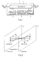
- FIG. 1 is a block diagram showing an example of a configuration of a frame interpolating circuit according to an embodiment of the present invention.
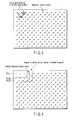
- FIG. 2 is a diagram for explaining an example of a former frame and a latter frame handled by a frame interpolating circuit according to an embodiment of the present invention.
- FIG. 3 is a diagram for explaining an example of a frame with a motion vector including a ghost caused by erroneous interpolation handled by a frame interpolating circuit according to an embodiment of the present invention.
- FIG. 4 is a diagram for explaining an example of a frame with a motion vector clipped at an upper left corner by a frame interpolating circuit according to an embodiment of the present invention.
- FIG. 1 is a block diagram showing an example of a configuration of a frame interpolating circuit according to an embodiment of the present invention.
- FIG. 2 is a diagram for explaining an example of a former frame and a latter frame handled by a frame interpolating circuit according to an embodiment of the present invention.
- FIG. 3 is
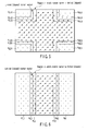
- FIG. 5 is a diagram for explaining an example of a frame with a motion vector clipped at four corners by a frame interpolating circuit according to an embodiment of the present invention.
- FIG. 6 is a diagram for explaining an example of a frame with a motion vector clipped at a left-side region and a right-side region by a frame interpolating circuit according to an embodiment of the present invention.
- FIG. 7 is a block diagram showing an example of a configuration of a display apparatus including a frame interpolating circuit according to an embodiment of the present invention.
- a frame interpolating circuit 1 in FIG. 1, for example, has a frame memory 11 which receives an input image signal I 1 having 60 frames/second of RGB standards or YCBCr standards as an example and outputs an output image signal I 2 having 120 frames/second as an example, and a motion vector detecting unit 12 which compares pixel values of a past frame (F1) and a present frame (F2) stored in the frame memory 11 to generate a motion vector by using symmetric searching, block matching, or the like.
- the frame interpolating circuit 1 has an in-screen region determining/vector value limiting circuit 13 which performs a vector value limiting process (described later), and an interpolated frame generating unit 14 which generates an interpolated frame (F3) on the basis of the past frame (F1) and the present frame (F2) from the motion vector detecting unit 12 and the motion vector generated by the motion vector detecting unit 12.
- a motion vector is detected from the input image signal (I 1 ) based on a past frame image (F1) and a present frame image (F2).
- the in-screen region determining/vector value limiting circuit 13 limits the motion vector such that only values of vectors in a predetermined region (described later) are made equal to or less than a predetermined value.
- the interpolated frame generating unit 14 receives a plurality of motion vectors, the vector values of which are partially limited, from the in-screen region determining/vector value limiting circuit 13 and generates an interpolated image (F3) on the basis of the past frame image (F1) and the present frame image (F2) from the input image signal (I 1 ) to output the interpolated image (F3) to the frame memory 11.
- the frame memory 11 outputs the past frame image (F1), the interpolated image (F3), and the present frame image (F2) to the subsequent part in the order named.
- the motion vector detecting unit 12 as a motion vector detecting method using block matching, the following method or the like is used. That is, a block having a predetermined shape is parallel moved symmetrically about a point on two former and latter frames which sandwich an insertion position of an interpolated frame image, differences of pixel values of pixels at the corresponding positions are calculated with respect to all pixels in the block to calculate an accumulated value (SAD: Sum of Absolute Difference) of the differences, and a direction in which the SAD value is minimum is used as a motion vector of the block.
- SAD Sum of Absolute Difference
- a broadcast station logo "ABC" or the like subjected to a blend process and shown on a normal video image as shown in FIG. 3 has a luminance component and a color component which are not different from those of a background video image. Therefore, in a block including a still object smaller than a block size used when block matching is performed, when a background video image is moving, it is determined that the logo image moves together with the background image, and defective display occurs in an interpolated image. For example, ghost is generated as shown in FIG. 3.
- a method of clipping a vector value (properly regulated to be equal to or smaller than a predetermined value and fixed) with respect to a specific region and processing a logo image as a still image is preferably performed.
- a logo or the like of a broadcast station is mostly shown at one of the four corners of a screen not to disturb a video image.
- a video image interested by a viewer is present at a center of the screen.
- the viewer rarely pays attention to the peripheral portion of the screen.
- a main object of interpolated frame formation is to improve moving image blur.
- an effect of improving a moving image blur sensed by the viewer is large at the center of the screen and small at the peripheral portion of the screen.
- a sensitivity to the feeling of moving image blur at the peripheral portion of the screen is not high, but a sensitivity to an erroneously interpolated video image at the peripheral portion of the screen is high to some extent. This is recognized as a broken video image.
- a limiting process according to an embodiment of the present invention has been made in consideration of the above point.
- an interpolated frame forming method which detects a motion vector
- an interpolated frame is formed by using a vector, the detected vector value of which is clipped to a predetermined value in a specific region in one screen (limited to be equal to or smaller than a predetermined value as needed).
- a video image is suppressed from being broken by erroneously interpolating the broadcast station logo or the like while keeping the effect of improving moving image blur.
- a motion vector to be detected is expressed as a moving distance of an object within transition time from the former frame to the interpolated frame or the interpolated frame to the rear frame.
- a motion vector having 8 pixels in an nearly horizontal direction and 3 pixels in a vertical direction is detected in a region in which a logo is not shown by the block matching process.
- a result depends on luminance and color components of a background video image and luminance and color components of the logo.
- the embodiment will be described below with reference to an example in which a motion vector having 8 pixels in a horizontal direction and 3 pixels in a vertical direction is detected.
- an interpolated frame is formed by using values obtained by clipping motion vectors detected by block matching at corner regions A LU1 , A LU2 , and A LU3 on the upper left of the screen.
- the regions A LU1 , A LU2 , and A LU3 in which amounts of clip are gradually changed are set to make it possible to suppress generation of the defect.
- a motion vector detected in the region A LU1 closest to the corner on the upper left of the screen is clipped by 2 pixels in the horizontal direction and one pixel in the vertical direction
- a motion vector detected in the region A LU2 first next to the region A LU1 is clipped by 4 pixels in the horizontal direction and 2 pixels in the vertical direction
- a motion vector detected in the region A LU3 first next to the region A LU2 is clipped in 6 pixels in the horizontal direction and 3 pixels in the vertical direction
- motion vectors detected by the vector detecting unit are directly used in the other regions.
- a method of changing a clip value of a motion vector is not limited to the example.
- the clip value can also be changed in finer steps.
- the clipping process (reducing process) of the vector value limiting circuit 13 when the four corners of a frame are used as specific regions as shown in FIG. 5, the left or right side of the frame is preferably used as the specific region as shown in FIG. 6.
- upper left specific regions A LU1 , A LU2 , and A LU3 are set by stepwisely increasing clip values.
- lower left specific regions A LD1 , A LD2 , and A LD3 are set by stepwisely increasing clip values.
- upper right specific regions A RU1 , A RU2 , and A RU3 are set by stepwisely increasing clip values.
- a panel display apparatus 30 using a frame interpolating circuit 1 has, as an example, a tuner unit 31 which outputs a broadcasting signal as a video signal, a scaler 32 which performs scaling process of the video signal, an IP converting unit 33 which performs IP conversion of the video signal, a processing unit 34 which includes color management, enhancer, a correcting circuit, and the like, the frame interpolating circuit 1 described above, and a panel unit 15 such as a liquid crystal display unit or an FPD (Flat Panel Display) which receives an output from the frame interpolating circuit 1.
- a tuner unit 31 which outputs a broadcasting signal as a video signal
- a scaler 32 which performs scaling process of the video signal
- IP converting unit 33 which performs IP conversion of the video signal
- a processing unit 34 which includes color management, enhancer, a correcting circuit, and the like
- the frame interpolating circuit 1 described above and a panel unit 15 such as a liquid crystal display unit or an FPD (Flat Panel Display
- the panel display apparatus 30 having such a configuration causes the frame interpolating circuit 1 to perform a clipping process (limiting process) of vector values in specific regions such as four corners as described above to make it possible to display a still image such as a logo without breakdown. For this reason, a smooth and natural video image can be displayed by using an interpolated frame without breaking the video image.
- a clipping process limiting process
Landscapes
- Engineering & Computer Science (AREA)
- Multimedia (AREA)
- Signal Processing (AREA)
- Television Systems (AREA)
- Image Analysis (AREA)
Applications Claiming Priority (1)
| Application Number | Priority Date | Filing Date | Title |
|---|---|---|---|
| JP2006244461A JP2008067194A (ja) | 2006-09-08 | 2006-09-08 | フレーム補間回路、フレーム補間方法、表示装置 |
Publications (1)
| Publication Number | Publication Date |
|---|---|
| EP1924099A1 true EP1924099A1 (fr) | 2008-05-21 |
Family
ID=39169780
Family Applications (1)
| Application Number | Title | Priority Date | Filing Date |
|---|---|---|---|
| EP20070016093 Withdrawn EP1924099A1 (fr) | 2006-09-08 | 2007-08-16 | Circuit d'interpolation de trame, procédé d'interpolation de trame et appareil d'affichage |
Country Status (3)
| Country | Link |
|---|---|
| US (1) | US20080063308A1 (fr) |
| EP (1) | EP1924099A1 (fr) |
| JP (1) | JP2008067194A (fr) |
Cited By (6)
| Publication number | Priority date | Publication date | Assignee | Title |
|---|---|---|---|---|
| WO2009158428A1 (fr) * | 2008-06-25 | 2009-12-30 | Qualcomm Incorporated | Référence fragmentaire en compression temporelle pour le codage vidéo |
| US8948270B2 (en) | 2008-08-19 | 2015-02-03 | Qualcomm Incorporated | Power and computational load management techniques in video processing |
| US8948822B2 (en) | 2008-04-23 | 2015-02-03 | Qualcomm Incorporated | Coordinating power management functions in a multi-media device |
| US8964828B2 (en) | 2008-08-19 | 2015-02-24 | Qualcomm Incorporated | Power and computational load management techniques in video processing |
| CN105872591A (zh) * | 2016-04-22 | 2016-08-17 | 北京小米移动软件有限公司 | 图标覆盖方法及装置 |
| CN107888927A (zh) * | 2011-01-31 | 2018-04-06 | 韩国电子通信研究院 | 图像解码/编码设备以及计算机可读记录介质 |
Families Citing this family (4)
| Publication number | Priority date | Publication date | Assignee | Title |
|---|---|---|---|---|
| JP4525692B2 (ja) * | 2007-03-27 | 2010-08-18 | 株式会社日立製作所 | 画像処理装置、画像処理方法、画像表示装置 |
| US8331710B2 (en) * | 2007-11-06 | 2012-12-11 | Sony Corporation | Image processing apparatus and method, learning apparatus and method, and program |
| US9762904B2 (en) * | 2011-12-22 | 2017-09-12 | Qualcomm Incorporated | Performing motion vector prediction for video coding |
| CN103634599B (zh) * | 2012-08-28 | 2017-07-04 | 北京京东方光电科技有限公司 | 一种视频处理方法、装置及显示装置 |
Citations (6)
| Publication number | Priority date | Publication date | Assignee | Title |
|---|---|---|---|---|
| GB2277002A (en) * | 1993-04-08 | 1994-10-12 | Sony Uk Ltd | Selecting motion vectors in video signal processing; global motion vectors. |
| US5546130A (en) * | 1993-10-11 | 1996-08-13 | Thomson Consumer Electronics S.A. | Method and apparatus for forming a video signal using motion estimation and signal paths with different interpolation processing |
| US5784114A (en) * | 1992-07-03 | 1998-07-21 | Snell & Wilcox Ltd | Motion compensated video processing |
| US6463102B1 (en) * | 1998-09-11 | 2002-10-08 | Harmonic, Inc. | Digital video compressor with border processor |
| WO2002087210A2 (fr) * | 2001-04-20 | 2002-10-31 | Koninklijke Philips Electronics N.V. | Procede et appareil d'estimation de vecteurs de mouvement |
| US20060017843A1 (en) * | 2004-07-20 | 2006-01-26 | Fang Shi | Method and apparatus for frame rate up conversion with multiple reference frames and variable block sizes |
Family Cites Families (10)
| Publication number | Priority date | Publication date | Assignee | Title |
|---|---|---|---|---|
| JPH08265770A (ja) * | 1995-03-20 | 1996-10-11 | Sony Corp | 高能率符号化方法、高能率符号化装置、記録再生装置及び情報伝送システム |
| US6690835B1 (en) * | 1998-03-03 | 2004-02-10 | Interuniversitair Micro-Elektronica Centrum (Imec Vzw) | System and method of encoding video frames |
| US6753865B1 (en) * | 1999-06-30 | 2004-06-22 | Realnetworks, Inc. | System and method for generating video frames and post filtering |
| JP2003299040A (ja) * | 2002-04-03 | 2003-10-17 | Sony Corp | 動きベクトル検出装置及び方法 |
| JP4053490B2 (ja) * | 2003-03-25 | 2008-02-27 | 株式会社東芝 | フレーム補間のための補間画像作成方法及びこれを用いた画像表示システム、補間画像作成装置 |
| JP3997171B2 (ja) * | 2003-03-27 | 2007-10-24 | 株式会社エヌ・ティ・ティ・ドコモ | 動画像符号化装置、動画像符号化方法、動画像符号化プログラム、動画像復号装置、動画像復号方法、及び動画像復号プログラム |
| KR100579493B1 (ko) * | 2003-06-16 | 2006-05-15 | 삼성전자주식회사 | 움직임 벡터 생성 장치 및 방법 |
| US7019616B2 (en) * | 2003-07-22 | 2006-03-28 | Fernandez Jorge D | Wireless message system with monitor feedback and automatic backup control |
| JP4371950B2 (ja) * | 2004-08-24 | 2009-11-25 | キヤノン株式会社 | 撮像装置及び信号処理装置 |
| KR100718135B1 (ko) * | 2005-08-24 | 2007-05-14 | 삼성전자주식회사 | 멀티 포맷 코덱을 위한 영상 예측 장치 및 방법과 이를이용한 영상 부호화/복호화 장치 및 방법 |
-
2006
- 2006-09-08 JP JP2006244461A patent/JP2008067194A/ja active Pending
-
2007
- 2007-08-16 EP EP20070016093 patent/EP1924099A1/fr not_active Withdrawn
- 2007-09-06 US US11/896,854 patent/US20080063308A1/en not_active Abandoned
Patent Citations (6)
| Publication number | Priority date | Publication date | Assignee | Title |
|---|---|---|---|---|
| US5784114A (en) * | 1992-07-03 | 1998-07-21 | Snell & Wilcox Ltd | Motion compensated video processing |
| GB2277002A (en) * | 1993-04-08 | 1994-10-12 | Sony Uk Ltd | Selecting motion vectors in video signal processing; global motion vectors. |
| US5546130A (en) * | 1993-10-11 | 1996-08-13 | Thomson Consumer Electronics S.A. | Method and apparatus for forming a video signal using motion estimation and signal paths with different interpolation processing |
| US6463102B1 (en) * | 1998-09-11 | 2002-10-08 | Harmonic, Inc. | Digital video compressor with border processor |
| WO2002087210A2 (fr) * | 2001-04-20 | 2002-10-31 | Koninklijke Philips Electronics N.V. | Procede et appareil d'estimation de vecteurs de mouvement |
| US20060017843A1 (en) * | 2004-07-20 | 2006-01-26 | Fang Shi | Method and apparatus for frame rate up conversion with multiple reference frames and variable block sizes |
Cited By (22)
| Publication number | Priority date | Publication date | Assignee | Title |
|---|---|---|---|---|
| US8948822B2 (en) | 2008-04-23 | 2015-02-03 | Qualcomm Incorporated | Coordinating power management functions in a multi-media device |
| RU2485712C2 (ru) * | 2008-06-25 | 2013-06-20 | Квэлкомм Инкорпорейтед | Фрагментированная ссылка во временном сжатии для кодирования видео |
| CN102067608B (zh) * | 2008-06-25 | 2013-12-04 | 高通股份有限公司 | 用于视频译码的时间压缩中的片段化参考 |
| US8908763B2 (en) | 2008-06-25 | 2014-12-09 | Qualcomm Incorporated | Fragmented reference in temporal compression for video coding |
| WO2009158428A1 (fr) * | 2008-06-25 | 2009-12-30 | Qualcomm Incorporated | Référence fragmentaire en compression temporelle pour le codage vidéo |
| US9565467B2 (en) | 2008-08-19 | 2017-02-07 | Qualcomm Incorporated | Power and computational load management techniques in video processing |
| US8948270B2 (en) | 2008-08-19 | 2015-02-03 | Qualcomm Incorporated | Power and computational load management techniques in video processing |
| US8964828B2 (en) | 2008-08-19 | 2015-02-24 | Qualcomm Incorporated | Power and computational load management techniques in video processing |
| US9462326B2 (en) | 2008-08-19 | 2016-10-04 | Qualcomm Incorporated | Power and computational load management techniques in video processing |
| CN107888927A (zh) * | 2011-01-31 | 2018-04-06 | 韩国电子通信研究院 | 图像解码/编码设备以及计算机可读记录介质 |
| CN108124162A (zh) * | 2011-01-31 | 2018-06-05 | 韩国电子通信研究院 | 图像解码/编码设备以及计算机可读记录介质 |
| CN108124161A (zh) * | 2011-01-31 | 2018-06-05 | 韩国电子通信研究院 | 图像解码/编码设备以及计算机可读记录介质 |
| CN108174219A (zh) * | 2011-01-31 | 2018-06-15 | 韩国电子通信研究院 | 图像解码/编码设备以及计算机可读记录介质 |
| US10645411B2 (en) | 2011-01-31 | 2020-05-05 | Electronics And Telecommunications Research Institute | Method and apparatus for encoding/decoding images using a motion vector |
| CN108124162B (zh) * | 2011-01-31 | 2020-11-24 | 韩国电子通信研究院 | 图像解码/编码设备以及计算机可读记录介质 |
| CN108124161B (zh) * | 2011-01-31 | 2020-11-24 | 韩国电子通信研究院 | 图像解码/编码设备以及计算机可读记录介质 |
| CN108174219B (zh) * | 2011-01-31 | 2020-11-24 | 韩国电子通信研究院 | 图像解码/编码设备以及计算机可读记录介质 |
| CN107888927B (zh) * | 2011-01-31 | 2020-11-24 | 韩国电子通信研究院 | 图像解码/编码设备以及计算机可读记录介质 |
| US12003753B2 (en) | 2011-01-31 | 2024-06-04 | Electronics And Telecommunications Research Institute | Method and apparatus for encoding/decoding images using a motion vector |
| US12028545B2 (en) | 2011-01-31 | 2024-07-02 | Electronics And Telecommunications Research Institute | Method and apparatus for encoding/decoding images using a motion vector |
| US12301859B2 (en) | 2011-01-31 | 2025-05-13 | Electronics And Telecommunications Research Institute | Method and apparatus for encoding/decoding images using a motion vector |
| CN105872591A (zh) * | 2016-04-22 | 2016-08-17 | 北京小米移动软件有限公司 | 图标覆盖方法及装置 |
Also Published As
| Publication number | Publication date |
|---|---|
| US20080063308A1 (en) | 2008-03-13 |
| JP2008067194A (ja) | 2008-03-21 |
Similar Documents
| Publication | Publication Date | Title |
|---|---|---|
| EP1924099A1 (fr) | Circuit d'interpolation de trame, procédé d'interpolation de trame et appareil d'affichage | |
| US8334932B2 (en) | Image processing device, image display device, and image processing method | |
| US8115867B2 (en) | Image processing device | |
| US7995146B2 (en) | Image processing apparatus and image processing method | |
| US8456578B2 (en) | Image processing apparatus and control method thereof for correcting image signal gradation using a gradation correction curve | |
| EP1811454A2 (fr) | Appareil et procédé de détermination de zone de contour | |
| CN102918830B (zh) | 图像处理装置和方法、图像显示装置和方法 | |
| US7822271B2 (en) | Method and apparatus of false color suppression | |
| US7688386B2 (en) | De-interlacing apparatus, de-interlacing method, and video display apparatus | |
| US7787047B2 (en) | Image processing apparatus and image processing method | |
| US8072465B2 (en) | Image processing method and system | |
| US20160086312A1 (en) | Image processing apparatus and image processing method | |
| US7903126B2 (en) | Image processing apparatus and image processing method thereof | |
| JP2009246735A (ja) | 映像信号補間装置、映像表示装置及び映像信号補間方法 | |
| JP4951487B2 (ja) | 映像処理装置及びそれを用いた映像表示装置 | |
| US20080063289A1 (en) | Frame interpolating circuit, frame interpolating method, and display apparatus | |
| US20120106648A1 (en) | Image processing device and video reproducing device | |
| EP1903803A2 (fr) | Circuit d'interpolation de trame, procédé d'interpolation de trame et appareil d'affichage | |
| US8115865B2 (en) | De-interlacing system with an adaptive edge threshold and interpolating method thereof | |
| US20100103313A1 (en) | Signal processor and signal processing method | |
| US7750974B2 (en) | System and method for static region detection in video processing | |
| JP2008028507A (ja) | 画像補正回路、画像補正方法および画像表示装置 | |
| US20060044471A1 (en) | Video signal setting device | |
| JP2010016489A (ja) | フレーム補間装置及びフレーム補間方法 | |
| JP2010057010A (ja) | 画像表示装置 |
Legal Events
| Date | Code | Title | Description |
|---|---|---|---|
| PUAI | Public reference made under article 153(3) epc to a published international application that has entered the european phase |
Free format text: ORIGINAL CODE: 0009012 |
|
| 17P | Request for examination filed |
Effective date: 20070816 |
|
| AK | Designated contracting states |
Kind code of ref document: A1 Designated state(s): AT BE BG CH CY CZ DE DK EE ES FI FR GB GR HU IE IS IT LI LT LU LV MC MT NL PL PT RO SE SI SK TR |
|
| AX | Request for extension of the european patent |
Extension state: AL BA HR MK RS |
|
| 17Q | First examination report despatched |
Effective date: 20080728 |
|
| AKX | Designation fees paid |
Designated state(s): DE FR GB |
|
| STAA | Information on the status of an ep patent application or granted ep patent |
Free format text: STATUS: THE APPLICATION IS DEEMED TO BE WITHDRAWN |
|
| 18D | Application deemed to be withdrawn |
Effective date: 20081209 |