EP1924123A2 - Appareil auditif - Google Patents
Appareil auditif Download PDFInfo
- Publication number
- EP1924123A2 EP1924123A2 EP07021860A EP07021860A EP1924123A2 EP 1924123 A2 EP1924123 A2 EP 1924123A2 EP 07021860 A EP07021860 A EP 07021860A EP 07021860 A EP07021860 A EP 07021860A EP 1924123 A2 EP1924123 A2 EP 1924123A2
- Authority
- EP
- European Patent Office
- Prior art keywords
- housing
- hearing aid
- signal
- unit
- fastening element
- Prior art date
- Legal status (The legal status is an assumption and is not a legal conclusion. Google has not performed a legal analysis and makes no representation as to the accuracy of the status listed.)
- Withdrawn
Links
Images

Classifications
-
- A—HUMAN NECESSITIES
- A61—MEDICAL OR VETERINARY SCIENCE; HYGIENE
- A61N—ELECTROTHERAPY; MAGNETOTHERAPY; RADIATION THERAPY; ULTRASOUND THERAPY
- A61N1/00—Electrotherapy; Circuits therefor
- A61N1/02—Details
- A61N1/04—Electrodes
- A61N1/05—Electrodes for implantation or insertion into the body, e.g. heart electrode
- A61N1/0526—Head electrodes
- A61N1/0541—Cochlear electrodes
-
- A—HUMAN NECESSITIES
- A61—MEDICAL OR VETERINARY SCIENCE; HYGIENE
- A61N—ELECTROTHERAPY; MAGNETOTHERAPY; RADIATION THERAPY; ULTRASOUND THERAPY
- A61N1/00—Electrotherapy; Circuits therefor
- A61N1/18—Applying electric currents by contact electrodes
- A61N1/32—Applying electric currents by contact electrodes alternating or intermittent currents
- A61N1/36—Applying electric currents by contact electrodes alternating or intermittent currents for stimulation
- A61N1/36036—Applying electric currents by contact electrodes alternating or intermittent currents for stimulation of the outer, middle or inner ear
- A61N1/36038—Cochlear stimulation
-
- H—ELECTRICITY
- H04—ELECTRIC COMMUNICATION TECHNIQUE
- H04R—LOUDSPEAKERS, MICROPHONES, GRAMOPHONE PICK-UPS OR LIKE ACOUSTIC ELECTROMECHANICAL TRANSDUCERS; ELECTRIC HEARING AIDS; PUBLIC ADDRESS SYSTEMS
- H04R25/00—Electric hearing aids
- H04R25/55—Electric hearing aids using an external connection, either wireless or wired
- H04R25/556—External connectors, e.g. plugs or modules
-
- H—ELECTRICITY
- H04—ELECTRIC COMMUNICATION TECHNIQUE
- H04R—LOUDSPEAKERS, MICROPHONES, GRAMOPHONE PICK-UPS OR LIKE ACOUSTIC ELECTROMECHANICAL TRANSDUCERS; ELECTRIC HEARING AIDS; PUBLIC ADDRESS SYSTEMS
- H04R2225/00—Details of deaf aids covered by H04R25/00, not provided for in any of its subgroups
- H04R2225/67—Implantable hearing aids or parts thereof not covered by H04R25/606
-
- H—ELECTRICITY
- H04—ELECTRIC COMMUNICATION TECHNIQUE
- H04R—LOUDSPEAKERS, MICROPHONES, GRAMOPHONE PICK-UPS OR LIKE ACOUSTIC ELECTROMECHANICAL TRANSDUCERS; ELECTRIC HEARING AIDS; PUBLIC ADDRESS SYSTEMS
- H04R2460/00—Details of hearing devices, i.e. of ear- or headphones covered by H04R1/10 or H04R5/033 but not provided for in any of their subgroups, or of hearing aids covered by H04R25/00 but not provided for in any of its subgroups
- H04R2460/13—Hearing devices using bone conduction transducers
Definitions
- the invention relates to a hearing aid with at least one external signal unit, wherein at least one implantable fastening element is provided for the signal unit equipped with a counter-fastening element.
- Such a hearing aid is in the DE 20 2004 006 117 U1 presented. This is about a bone conduction hearing aid with magnetic coupling.
- This has an external signal unit in the form of a vibrator. The signal is transmitted from the vibrator to an associated magnet. The aforesaid magnet is fixed by a second, surgically implanted magnet.
- the sound generated by the vibrator is transmitted as solid-state sound through the skin and subcutaneous tissue in the implanted magnet and from there into an immediately adjacent bone.
- This is designed as bone hearing aid, in which in addition to the local signal unit or a signal processing and amplifying unit, an electromechanical transducer is realized in the form of a vibrator.
- the electromechanical transducer may be applied directly to the cranial bone or the so-called mastoid of a user. In this way, his vibrations are transmitted via structure-borne noise to the functional inner ear of the user in question.
- the known hearing aid is releasably attached to a mounting bracket bow. This has proven itself in principle.
- DE 39 18 329 A1 also generic hearing aids that are, however, used for electrical stimulation of the (human) inner ear. These are equipped with hearing aids via an implantable stimulus electrode assembly.
- the external signal unit is in this case inductively coupled to the stimulation electrode arrangement.
- the procedure is usually that acoustic signals are converted by means of the signal unit into electrical signals, which in turn act on the stimulation electrode arrangement.
- the stimulus electrode assembly may have a spherical active electrode and a neutral electrode.
- the active electrode can be introduced, for example, into the human inner ear and here electrically irritate the auditory nerve or stimuli that are still present there. This creates a sense of hearing, with the help of the deaf and phoneertaubte after a certain training time can hear for the first time or again.
- the signal unit does not - as with the DE 39 18 329 A1 - Executed as behind the ear to be worn housing, but is housed in a bag to be carried. From this bag, a connecting cable extends to a transmitting antenna, which is carried in the area of the respective ear.
- the invention is the technical problem of further developing a hearing aid of the embodiment described above so that the comfort is significantly improved.
- a generic hearing aid in the invention is characterized in that a Signal unit receiving housing or signal housing is made of a signal unit enclosing curing plastic mass.
- the signal unit or the individual elements of the signal unit are advantageously enclosed by the plastic compound in question by an encapsulation process, which at the same time defines the signal housing as such.
- the signal housing can be easily adapted to color preferences of the operator.
- the signal unit is held by the interaction of fastener and mating fastener on the head of an operator, preferably releasably.
- the fastening element and the counter-fastening element are two magnets.
- a magnet and a magnetizable element for example a steel disc, a steel plate or the like. As a result, the wearing comfort is enormously improved.
- the outer ear as the same carrier of the signal housing according to the invention is no longer needed (see. DE 39 18 329 A1 ).
- complicated pocket solutions as used in the U.S. Patent 4,532,930 to be introduced. Rather, the signal unit is practically free at the head of an operator, advantageously behind the ear, (releasably) held. Additional holding measures, such as the outer ear, if necessary, a temples or a carrying handle are not (anymore) required (see. DE 20 2005 009 021 U1 ).
- the invention advantageously takes advantage of (neodymium) permanent magnets that build extremely small and easily build the required holding forces.
- the signal unit and with it the signal housing can be made extremely compact, because the individual components of the signal unit require little space due to the increasing miniaturization in the electronics sector. It is observed at this point volumes for the signal housing, which are in the range of about 1 cm 3 or even below, are therefore not perceived by a user as disturbing.
- the weight is located in the range of a few grams ( ⁇ 0.1 N), so that the magnets used can easily apply the required to fix the signal unit or the signal housing holding forces.
- a particularly advantageous attachment of the signal unit is realized when two or more pairs of the fastening element / counter-fastening element are realized. For example, it has proven useful if the corresponding pairs are each placed at the edge of the signal housing for receiving the signal unit. This is easily possible, especially since the signal housing is designed as a capsule-like plastic housing and has a rounded cuboid shape.
- a further adaptation is possible in such a way that the fastening element and / or the counter-fastening element are adjustable, in particular height-adjustable, are formed.
- This allows the distance of a base plate of the signal housing from the contact surface on the head of the operator change. This measure contributes additionally to the increase in wearing comfort.
- the base plate may be interchangeable and designed as an impression plate. This makes it possible to take an impression of the contact surface on the head of the operator and adjust in this way, the base plate in the signal housing to the respective operator.
- the signal unit has - as already stated - several elements. These include regularly at least one microphone, a signal processor and a transmitting coil assembly. Alternatively or additionally, a signal processing and amplification unit as well as an electromechanical converter may also belong to the signal unit. With the help of the signal processor or the signal processing and amplification unit, the acoustic signals recorded by the microphone are converted into electrical signals.
- these electrical signals control the electromechanical transducer, which in this way is set in the desired vibrations.
- the electrical signals in question are forwarded to the transmitting coil arrangement, which is inductively coupled to an implanted receiving coil arrangement.
- the receiver coil assembly is electrically connected to the stimulus electrode assembly.
- the receive coil assembly may include an optionally provided receive processor from which the one or more electrodes of the stimulus electrode assembly emanate to electrically excite the inner ear as described.
- the electrical signals can be converted into digital signals or are present as such and therefore represent digital data to be processed by computation.
- Conventional algorithms can be used for this purpose Are used, which prepare the acoustic signals for the subsequent activation of the electromechanical transducer or the subsequent wireless coupling with the stimulation electrode assembly operator-dependent.
- this is understood as an adaptation which, depending on the anatomy of the inner ear of the operator or patient, carries out individual signal processing in the signal processor or in the signal processing and amplification unit.
- the adaptation in question is stored as a user-dependent software program in the signal processor or the signal processing and amplification unit.
- the software controlling the signal processor or the signal processing and amplification unit can be updated without difficulty.
- a power supply unit such as battery, can be exchanged according to rotation, which is also accommodated in the signal housing.
- the signal housing designed as a capsule-like plastic housing has a closable opening for receiving the relevant energy supply unit.
- the signal unit may advantageously be arranged on a bone area lying behind the outer ear, the so-called mastoid.
- this bone region or mastoid is particularly advantageous for implanting the fasteners.
- the mastoid receives the stimulation electrode arrangement required for this purpose.
- the mastoid serves to transmit the vibrations of the electromechanical transducer to the inner ear by means of structure-borne noise.
- a hearing aid which has a hitherto unknown wearing comfort. Because the obligatory external signal unit can be easily removed from the contact surface on the head of the operator or patient. A re-attachment is not difficult, because the interaction of implanted fastener and external counter-fastening element on or in the signal unit based only on magnetic holding forces. These can easily be picked up and restored.
- the main benefits are the main benefits.
- Fig. 1 can be seen a human ear partially in section. This is divided into the outer ear with auricle 1 and the external auditory canal 2, the middle ear 3 and finally the inner ear 4, which is of particular importance for the following considerations.
- a bone hearing aid according to FIG. 1 which rests with the aid of an electromechanical transducer 11 'in the form of a vibrator on the mastoid of the user and in this way vibrations of the electromechanical transducer 11' by means of structure-borne noise to the inner ear itself functional 4 transmits.
- the hearing aid is used for electrical stimulation of the above-mentioned inner ear 4.
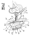
- the hearing aid in question has a implantable stimulation electrode assembly 5, 6, 7, 8, 9, 10, which is shown in the accompanying Fig. 2.
- the stimulation electrode arrangement 5, 6, 7, 8, 9, 10 is composed in detail of a reception coil arrangement 5 and a reception processor 6 which processes the signals of the reception coil arrangement 5.
- Receiving coil assembly 5 and receiving processor 6 are housed together in a biocompatible and hermetically sealed housing 7, which is implanted under the scalp 16 of a patient or operator, in the bone area behind the outer ear or the auricle 1 (mastoid). This location is recommended because of the small number of nerve cords in this area.
- the high-frequency electrical signals received with the aid of the receiving coil arrangement 5 from a transmitting coil arrangement 11 of the signal unit 11, 11 ', 12, 13, 14, 14', 14 ", 15 are processed in the receiving processor 6 and forwarded to an electrode 10 in the inner ear 4, which
- the active electrode 10 in question is turned over by a neutral electrode 8, which covers a supply line of the active electrode 10.
- the active electrode 10 is penetrated through a window 9 into the inner ear 4 and in the area of the auditory nerve.
- the external signal unit 11, 11 ', 12, 13, 14, 14', 14 ", 15 is composed of the already mentioned transmitting coil arrangement 11, a power supply device 12, in this case a battery, a microphone 13, a signal processor 14 and finally a housing or housing Signal housing 15 in the context of the embodiment of FIG. 2 together, which encloses the entire local signal unit 11, 12, 13, 14, 15 and the above-mentioned elements 11, 12, 13, 14.
- the signal unit 11 ', 12, 13, 14', 14 ", 15 comprises the already mentioned electromechanical converter 11 ', the energy supply device 12, the microphone 13, a signal processing unit 14' and an amplification unit 14" and Finally, the housing 15.
- the signal processing unit 14 ' influenced by the microphone 13 recorded signal spectrum of the acoustic signal in such a way that tends to high frequencies more than low frequencies are amplified. As a result, the subsequent structure-borne sound transmission by means of the electromechanical transducer 11 'is taken into account.
- the respective acoustic signal After the respective acoustic signal has been processed in the described manner, it is amplified in the amplification unit 14 "and transmitted to the electromechanical transducer 11 'in question in order to stimulate it to vibrate (see Fig. 1) Housing 15, the elements 11 ', 12, 13, 14' and 14 ".
- the housing or signal housing 15 is made of a hardening plastic compound and is produced in that the individual elements 11, 11 ', 13, 14 and 14', 14 "- except for the power supply device 12 - taken together by the curing plastic mass encapsulated and embedded therein simultaneously to form the housing 15.
- the housing or signal housing 15 can be designed, for example, transparent or colored according to the wishes of the operator.
- At least one Fastening element 17 is implanted.
- two implanted or implantable fasteners 17 are provided, which are arranged in the immediate vicinity of the housing 7 for receiving the receiving coil assembly 5 and the receiving processor 6 under the scalp 16, again in the mastoid (see Fig .. 2).
- the attachment of the fasteners 17 also takes place in said bone area, but locally practically freely selectable.
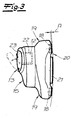
- the counter-fastening elements 18 are accommodated and located in the interior of the signal housing 15 As shown in FIG. 3 each in both ends cantilevers 19 of the capsule-like and rounded cuboid signal housing 15th
- the respective fastening element 17 and the associated counter-fastening element 18 are two magnets 17, 18 or even a magnet 17 and a magnetizable element 18, such as a steel disk or iron disk.
- the external signal unit 11, 11 ', 12, 13, 14, 14', 14 ", 15 with the aid of their counter-fastening element 18 and its two counter-fastening elements 18 releasably on the implanted or implantable fastener 17 and the two fasteners 17 solvable established.
- the signal unit 11, 11 ', 12, 13, 14, 14', 14 ", 15 can be easily removed, for example, for exchanging the energy supply device or battery 12 from the attachment point in question at a contact surface 20 at the head of the operator Attach the replacement and / or update of the signal processor 14 and / or the signal processing and amplification unit 14 ', 14 "with new and improved software.
- the adhesive forces applied by the magnets or the respective magnet 17, 18 and the magnetizable element 17, 18 are in each case sufficient to hold the signal housing 15, which weighs only a few grams, at the defined location in the area of the contact surface 20.
- disc-like magnets with a circular diameter which have a radius of only a few millimeters and a thickness also in the millimeter range, thus can be easily implanted. Nevertheless, adhesive forces in the range of> 0.1 N are applied, which clearly exceed the weight forces of ⁇ 0.1 N.
- two pairs of fastening element 17 / counter-fastening element 18 are provided in the context of the exemplary embodiment, each of which is located on the edge side of the signal housing 15. It is clear from FIG. 3 that the counter-fastening elements 18 installed in the signal housing 15 are designed to be adjustable. Basically, the Fixing elements 17 are adjusted, which is not shown. Due to the height adjustability of the counter-fastening elements 18, their distance A from the fastening elements 17 can be changed and consequently also the distance of the base plate 21 of the signal housing 15 from the contact surface 20 at the head of the operator.
- the questionable base plate 21 is designed to be interchangeable and can be designed as an impression plate. In this way, the operator can take an impression of the contact surface 20 and thus adjust the base plate 21 to the contour of the contact surface 20 individually to increase the wearing comfort. This also contributes to the possibility, as it were, to vary the contact pressure of the signal housing 15 to the contact surface 20 in question in that the counter-fastening elements 18 are adjusted in height accordingly.
- the counter-fastening elements 18 are equipped with an indicated threaded pin, which dips into a thread in the signal housing 15 in order to change the distance A in question can.
- the signal housing 15 has a closable by means of a lid 23 opening or recess 22 which is equipped to accommodate the replaceable power supply unit 12.
- the transmitting coil arrangement 11 can be displaced relative to the signal housing 15 and consequently also the scalp 16 of the operator.
- any irregularities of the contact surface 20 is taken into account and can be an optimal conditioning of the signal housing 15 on the contact surface 20 as well as a perfect wireless coupling of one hand, the transmitting coil assembly 11 and the other hand, the receiving coil assembly 5.
- the electromechanical transducer 11 '. 1 which is also slidably mounted relative to the scalp 16 and consequently the housing 15 in this.
Landscapes
- Health & Medical Sciences (AREA)
- Engineering & Computer Science (AREA)
- Otolaryngology (AREA)
- General Health & Medical Sciences (AREA)
- Biomedical Technology (AREA)
- Public Health (AREA)
- Nuclear Medicine, Radiotherapy & Molecular Imaging (AREA)
- Radiology & Medical Imaging (AREA)
- Life Sciences & Earth Sciences (AREA)
- Animal Behavior & Ethology (AREA)
- Veterinary Medicine (AREA)
- Heart & Thoracic Surgery (AREA)
- Cardiology (AREA)
- Computer Networks & Wireless Communication (AREA)
- Neurosurgery (AREA)
- Physics & Mathematics (AREA)
- Acoustics & Sound (AREA)
- Signal Processing (AREA)
- Prostheses (AREA)
- Headphones And Earphones (AREA)
Applications Claiming Priority (1)
| Application Number | Priority Date | Filing Date | Title |
|---|---|---|---|
| DE202006017662U DE202006017662U1 (de) | 2006-11-17 | 2006-11-17 | Hörgerät |
Publications (2)
| Publication Number | Publication Date |
|---|---|
| EP1924123A2 true EP1924123A2 (fr) | 2008-05-21 |
| EP1924123A3 EP1924123A3 (fr) | 2009-12-09 |
Family
ID=38513813
Family Applications (1)
| Application Number | Title | Priority Date | Filing Date |
|---|---|---|---|
| EP07021860A Withdrawn EP1924123A3 (fr) | 2006-11-17 | 2007-11-10 | Appareil auditif |
Country Status (2)
| Country | Link |
|---|---|
| EP (1) | EP1924123A3 (fr) |
| DE (1) | DE202006017662U1 (fr) |
Cited By (2)
| Publication number | Priority date | Publication date | Assignee | Title |
|---|---|---|---|---|
| DE202023100591U1 (de) | 2023-02-08 | 2023-03-14 | Ao Riedel Gmbh | Hörsystem mit dekorativem Element |
| DE102023103016A1 (de) | 2023-02-08 | 2024-08-08 | Ao Riedel Gmbh | Hörsystem |
Families Citing this family (10)
| Publication number | Priority date | Publication date | Assignee | Title |
|---|---|---|---|---|
| WO2012010195A1 (fr) | 2010-07-19 | 2012-01-26 | Advanced Bionics Ag | Instrument auditif et procédé de fonctionnement associé |
| US9022917B2 (en) * | 2012-07-16 | 2015-05-05 | Sophono, Inc. | Magnetic spacer systems, devices, components and methods for bone conduction hearing aids |
| WO2017087004A1 (fr) | 2015-11-20 | 2017-05-26 | Advanced Bionics Ag | Implants cochléaires et aimants pour utilisation avec ceux-ci |
| WO2017105511A1 (fr) | 2015-12-18 | 2017-06-22 | Advanced Bionics Ag | Implants cochléaires comprenant un appareil magnétique compatible avec l'irm |
| WO2018190813A1 (fr) | 2017-04-11 | 2018-10-18 | Advanced Bionics Ag | Implants cochléaires avec aimants rapportés |
| EP3615132B1 (fr) | 2017-04-25 | 2022-09-21 | Advanced Bionics AG | Implants cochléaires équipés d'un appareil à aimant compatible avec l'irm résistant aux chocs |
| WO2019083540A1 (fr) | 2017-10-26 | 2019-05-02 | Advanced Bionics Ag | Modules externes et systèmes de stimulation cochléaire implantables comprenant ceux-ci |
| US20210046311A1 (en) | 2018-02-15 | 2021-02-18 | Advanced Bionics Ag | Headpieces and implantable cochlear stimulation systems including the same |
| WO2021201845A1 (fr) | 2020-03-31 | 2021-10-07 | Advanced Bionics Ag | Modules externes et systèmes de stimulation cochléaire implantables comprenant ces derniers |
| US12440668B2 (en) | 2021-10-12 | 2025-10-14 | Advanced Bionics Ag | Cochlear implants having MRI-compatible magnet apparatus and associated systems and methods |
Citations (4)
| Publication number | Priority date | Publication date | Assignee | Title |
|---|---|---|---|---|
| US4532930A (en) | 1983-04-11 | 1985-08-06 | Commonwealth Of Australia, Dept. Of Science & Technology | Cochlear implant system for an auditory prosthesis |
| DE3918329A1 (de) | 1989-06-05 | 1990-12-06 | Hortmann Gmbh | Hoergeraet zur elektrischen reizung des innenohres |
| DE202004006117U1 (de) | 2004-04-15 | 2004-07-08 | Siegert, Ralf, Prof. Dr. Dr.med. | Knochenleitungshörgerät mit Magnetankopplung |
| DE202005009021U1 (de) | 2005-06-09 | 2005-08-11 | Bagus Gmbh & Co.Kg | Hörgerät, insbesondere Knochenhörgerät |
Family Cites Families (4)
| Publication number | Priority date | Publication date | Assignee | Title |
|---|---|---|---|---|
| DE19742470A1 (de) * | 1997-09-26 | 1999-04-29 | Mannesmann Vdo Ag | Verfahren zum Herstellen eines elektrischen Gerätes mit Gehäuse |
| FR2841429B1 (fr) * | 2002-06-21 | 2005-11-11 | Mxm | Dispositif d'aide auditive pour la rehabilitation de patients ateints de surdites neurosensorielles partielles |
| DE202005009361U1 (de) * | 2005-06-09 | 2006-10-12 | Siegert, Ralf, Prof. Dr. Dr.med. | Knochenleitungshörgerät mit Doppelmagnetankopplung |
| US20070053536A1 (en) * | 2005-08-24 | 2007-03-08 | Patrik Westerkull | Hearing aid system |
-
2006
- 2006-11-17 DE DE202006017662U patent/DE202006017662U1/de not_active Expired - Lifetime
-
2007
- 2007-11-10 EP EP07021860A patent/EP1924123A3/fr not_active Withdrawn
Patent Citations (4)
| Publication number | Priority date | Publication date | Assignee | Title |
|---|---|---|---|---|
| US4532930A (en) | 1983-04-11 | 1985-08-06 | Commonwealth Of Australia, Dept. Of Science & Technology | Cochlear implant system for an auditory prosthesis |
| DE3918329A1 (de) | 1989-06-05 | 1990-12-06 | Hortmann Gmbh | Hoergeraet zur elektrischen reizung des innenohres |
| DE202004006117U1 (de) | 2004-04-15 | 2004-07-08 | Siegert, Ralf, Prof. Dr. Dr.med. | Knochenleitungshörgerät mit Magnetankopplung |
| DE202005009021U1 (de) | 2005-06-09 | 2005-08-11 | Bagus Gmbh & Co.Kg | Hörgerät, insbesondere Knochenhörgerät |
Cited By (3)
| Publication number | Priority date | Publication date | Assignee | Title |
|---|---|---|---|---|
| DE202023100591U1 (de) | 2023-02-08 | 2023-03-14 | Ao Riedel Gmbh | Hörsystem mit dekorativem Element |
| DE102023103016A1 (de) | 2023-02-08 | 2024-08-08 | Ao Riedel Gmbh | Hörsystem |
| EP4415392A1 (fr) | 2023-02-08 | 2024-08-14 | AO Riedel GmbH | Système de chas |
Also Published As
| Publication number | Publication date |
|---|---|
| DE202006017662U1 (de) | 2007-09-06 |
| EP1924123A3 (fr) | 2009-12-09 |
Similar Documents
| Publication | Publication Date | Title |
|---|---|---|
| EP1924123A2 (fr) | Appareil auditif | |
| DE3617118C2 (fr) | ||
| EP1246503B1 (fr) | Système auditif entièrement implantable | |
| DE10047388C1 (de) | Mindestens teilweise implantierbares Hörsystem | |
| DE10018334C1 (de) | Mindestens teilimplantierbares System zur Rehabilitation einer Hörstörung | |
| EP0340594B1 (fr) | Dispositif de prothèse auditive à commande à distance sans fil | |
| EP0812577B1 (fr) | Système de positionnement et fixation implantable pour implants actoriques et sensoriels | |
| DE19882589B3 (de) | Wandler mit piezoelektrischem Film | |
| EP1179969B1 (fr) | Système auditif au moins partiellement implantable | |
| DE10320863B3 (de) | Befestigung eines Hörhilfegerätes oder einer Otoplastik im Ohr | |
| EP1583395B1 (fr) | Prothèse auditive intra-auriculaire pour le traitement binaural d'un patient | |
| EP0193145A2 (fr) | Système de transmission pour prothèses auditives | |
| DE102007045315B3 (de) | Werkzeug zum Einsetzen eines Hörers einer Hörvorrichtung in einen Gehörgang | |
| EP1962553A2 (fr) | Dispositif auditif doté d'un dispositif de support de batterie fixé magnétiquement | |
| DE3918329A1 (de) | Hoergeraet zur elektrischen reizung des innenohres | |
| DE10048337C1 (de) | Hinter dem Ohr tragbares Hörhilfegerät | |
| EP0821542A2 (fr) | Prothèse auditive portable complètement dans le conduit auditif et individualisée par moulage d'un corps | |
| DE102005006404B3 (de) | Modulares Hörgerätesystem | |
| DE102008037979A1 (de) | Befeldungsgerät zur Befeldung von Körperteilen von Lebewesen mit elektromagnetischen Wellen | |
| DE112017003844B4 (de) | Vorrichtung zur patientenschonenden Kopplung an Hörgeräten | |
| DE202005009021U1 (de) | Hörgerät, insbesondere Knochenhörgerät | |
| EP2144455A2 (fr) | Casque d'écoute destiné à la conduction osseuse du son | |
| EP0345345B1 (fr) | Transducteur electro-acoustique | |
| DE2802602C2 (fr) | ||
| EP0544677B1 (fr) | Prothese auditive electromagnetique de l'oreille moyenne |
Legal Events
| Date | Code | Title | Description |
|---|---|---|---|
| PUAI | Public reference made under article 153(3) epc to a published international application that has entered the european phase |
Free format text: ORIGINAL CODE: 0009012 |
|
| AK | Designated contracting states |
Kind code of ref document: A2 Designated state(s): AT BE BG CH CY CZ DE DK EE ES FI FR GB GR HU IE IS IT LI LT LU LV MC MT NL PL PT RO SE SI SK TR |
|
| AX | Request for extension of the european patent |
Extension state: AL BA HR MK RS |
|
| PUAL | Search report despatched |
Free format text: ORIGINAL CODE: 0009013 |
|
| AK | Designated contracting states |
Kind code of ref document: A3 Designated state(s): AT BE BG CH CY CZ DE DK EE ES FI FR GB GR HU IE IS IT LI LT LU LV MC MT NL PL PT RO SE SI SK TR |
|
| AX | Request for extension of the european patent |
Extension state: AL BA HR MK RS |
|
| AKY | No designation fees paid | ||
| STAA | Information on the status of an ep patent application or granted ep patent |
Free format text: STATUS: THE APPLICATION IS DEEMED TO BE WITHDRAWN |
|
| 18D | Application deemed to be withdrawn |
Effective date: 20100610 |
|
| REG | Reference to a national code |
Ref country code: DE Ref legal event code: 8566 |