EP1924313B1 - Medizinisches instrument - Google Patents
Medizinisches instrument Download PDFInfo
- Publication number
- EP1924313B1 EP1924313B1 EP06805690A EP06805690A EP1924313B1 EP 1924313 B1 EP1924313 B1 EP 1924313B1 EP 06805690 A EP06805690 A EP 06805690A EP 06805690 A EP06805690 A EP 06805690A EP 1924313 B1 EP1924313 B1 EP 1924313B1
- Authority
- EP
- European Patent Office
- Prior art keywords
- guide tube
- instrument according
- cannula
- syringe
- receiving means
- Prior art date
- Legal status (The legal status is an assumption and is not a legal conclusion. Google has not performed a legal analysis and makes no representation as to the accuracy of the status listed.)
- Not-in-force
Links
Images


Classifications
-
- A—HUMAN NECESSITIES
- A61—MEDICAL OR VETERINARY SCIENCE; HYGIENE
- A61M—DEVICES FOR INTRODUCING MEDIA INTO, OR ONTO, THE BODY; DEVICES FOR TRANSDUCING BODY MEDIA OR FOR TAKING MEDIA FROM THE BODY; DEVICES FOR PRODUCING OR ENDING SLEEP OR STUPOR
- A61M25/00—Catheters; Hollow probes
- A61M25/01—Introducing, guiding, advancing, emplacing or holding catheters
- A61M25/06—Body-piercing guide needles or the like
- A61M25/0662—Guide tubes
-
- A—HUMAN NECESSITIES
- A61—MEDICAL OR VETERINARY SCIENCE; HYGIENE
- A61M—DEVICES FOR INTRODUCING MEDIA INTO, OR ONTO, THE BODY; DEVICES FOR TRANSDUCING BODY MEDIA OR FOR TAKING MEDIA FROM THE BODY; DEVICES FOR PRODUCING OR ENDING SLEEP OR STUPOR
- A61M25/00—Catheters; Hollow probes
- A61M25/0067—Catheters; Hollow probes characterised by the distal end, e.g. tips
- A61M25/0068—Static characteristics of the catheter tip, e.g. shape, atraumatic tip, curved tip or tip structure
- A61M25/007—Side holes, e.g. their profiles or arrangements; Provisions to keep side holes unblocked
-
- A—HUMAN NECESSITIES
- A61—MEDICAL OR VETERINARY SCIENCE; HYGIENE
- A61M—DEVICES FOR INTRODUCING MEDIA INTO, OR ONTO, THE BODY; DEVICES FOR TRANSDUCING BODY MEDIA OR FOR TAKING MEDIA FROM THE BODY; DEVICES FOR PRODUCING OR ENDING SLEEP OR STUPOR
- A61M25/00—Catheters; Hollow probes
- A61M25/0067—Catheters; Hollow probes characterised by the distal end, e.g. tips
- A61M25/0082—Catheter tip comprising a tool
- A61M25/0084—Catheter tip comprising a tool being one or more injection needles
-
- A—HUMAN NECESSITIES
- A61—MEDICAL OR VETERINARY SCIENCE; HYGIENE
- A61M—DEVICES FOR INTRODUCING MEDIA INTO, OR ONTO, THE BODY; DEVICES FOR TRANSDUCING BODY MEDIA OR FOR TAKING MEDIA FROM THE BODY; DEVICES FOR PRODUCING OR ENDING SLEEP OR STUPOR
- A61M25/00—Catheters; Hollow probes
- A61M25/0097—Catheters; Hollow probes characterised by the hub
-
- A—HUMAN NECESSITIES
- A61—MEDICAL OR VETERINARY SCIENCE; HYGIENE
- A61M—DEVICES FOR INTRODUCING MEDIA INTO, OR ONTO, THE BODY; DEVICES FOR TRANSDUCING BODY MEDIA OR FOR TAKING MEDIA FROM THE BODY; DEVICES FOR PRODUCING OR ENDING SLEEP OR STUPOR
- A61M25/00—Catheters; Hollow probes
- A61M2025/0008—Catheters; Hollow probes having visible markings on its surface, i.e. visible to the naked eye, for any purpose, e.g. insertion depth markers, rotational markers or identification of type
Definitions
- the invention relates to a medical instrument according to the preamble of patent claim 1.
- a cannula is inserted into a channel of the patient's body to pierce the wall of the body canal or pierce the wall of the body canal.
- the cannula may be an injection cannula to deliver a drug, e.g. B. to apply an anesthetic in the wall of the body passage.
- a drug e.g. B. to apply an anesthetic in the wall of the body passage.
- An example of such an application is the injection of a local anesthetic into the wall of the cervical canal during intrauterine procedures, such as surgery. B. when inserting a spiral.
- Another example is the injection of drugs, e.g. For example, injection of hyaluronic acid into the tissue surrounding the urethra for the treatment of urinary incontinence or for the treatment of vesicoureteral reflux in children.
- the cannula may also be a puncture or biopsy cannula to pierce the wall of the body passage and remove body fluid or tissue samples.
- biopsy cannulas can also be designed as punching cannulas. Biopsy punctures are performed, for example, for tissue removal from the prostate transrectal or transperineal.
- the cannula is inserted through the channel of the body and then has to be biased against the axis of the body passage to pierce the wall of the body passage with the distal tip of the cannula.
- the lumen of the body canal generally leaves only one relatively small angle between the axis of the body passage and the axis of the cannula so that only a shallow puncture in the wall of the body passage is possible.
- the puncture site in the wall in the axial direction is only inaccurately determined.
- Intrauterinspirale in the uterus is z. B. for the patient extremely painful, since the introducer for Intrauterinspirale by the very sensitive on stretch stimuli internal cervix (os internum) is introduced. It is therefore advantageous to deposit an anesthetic in the region of the internal cervix. This can be done with an injection cannula next to the cervix in the posterior vaginal vault. This is problematic because the puncture is painful and the injection cannula must be advanced through the tissue over a relatively long distance, with blood vessels also being in this area.
- Another possibility is to introduce a very thin injection cannula into the cercix canal and to inject the local anesthetic through the wall of the cervical canal into the musculature of the internal cervical os.
- the above-described problems may occur in that the injection cannula penetrates into the wall during advancement in the cervical canal, since the inside of the cervical canal has a mucous membrane with an irregular surface and the walls practically abut one another. An optimal desired position of the puncture site in the wall of the cervical canal in the region of the inner cervical os is therefore hardly possible.
- the penetration angle for piercing the cannula is limited by the vaginal lumen expanded by a spread speculum.
- the guide tube has an axial guide channel for the cannula, which is bent at the distal end of the guide tube and extends to a laterally arranged on the circumference of the guide tube opening.
- the distal tip of the cannula deflects and exits laterally at an angle to the axis of the guide tube through the opening.
- the cannula can thus be inserted into the wall of the body passage of the patient at the angle given by the opening against the axis of the guide tube. If several recesses distributed over the circumference of the body channel are required, then the entire instrument must be rotated about its axis, resulting in unfavorable handling.
- a medical instrument according to the preamble of claim 1 is known from the document WO 2005/044357 A known.
- the invention is therefore based on the object to provide a medical instrument according to the preamble of claim 1 is available, which is easy to use and flexible in the uses.
- the medical instrument according to the invention has a guide tube with an axial guide channel which extends at the distal end bent outwards and opens into a laterally arranged on the circumference of the guide tube opening.
- a cannula can be pushed, the distal tip is deflected when advancing at the distal end of the guide channel from the axis of the guide tube and angled towards the axis of the guide tube exits laterally from the guide tube to stab into the wall of a body passage of the patient, in which the guide tube was inserted.
- the guide tube is rotatably mounted with its proximal end about its longitudinal axis in a handle part.
- easy handling is possible because the doctor can hold the handle firmly in his hand, without having to change the position of the handle part and thus his hand position.
- the axial position of the distal end of the guide tube and thus the puncture point emerging from the guide tube Cannula is determined by the position of the handle portion, so that the axial position of the puncture sites in different angular positions can be easily and reliably maintained.
- the guide tube has only one axial guide channel, so that the diameter and cross section of the guide tube need not be substantially larger than the diameter and the cross section of the inserted cannula.
- the guide tube can be rotated arbitrarily about its longitudinal axis, so that punctures in any angular position are possible. This results in a high flexibility in the application, since the number of punctures and their mutual angular position can be chosen arbitrarily.
- a mark is provided on the proximal end of the guide tube accommodated in the grip part, on which the treating doctor can recognize in which rotational angle position the guide tube and thus the opening for the exit of the cannula tip are located.
- a substantially radially projecting actuating lever is attached to the proximal end of the guide tube, on the one hand enables a simple sensitive rotation of the guide tube and on the other hand serves as a marker for the rotational angular position.
- the guide tube is releasably attached to the handle portion so that the instrument can be disassembled for thorough cleaning and sterilization.
- the guide tube at its proximal end on an outer collar, which in a bearing ring is rotatably mounted at the distal end of the handle part.
- the actuating lever may be used, wherein it passes radially through a circumferential slot of the bearing ring. The actuating lever serves in this way both for rotating the guide tube, for displaying the rotational angular position of the guide tube and for axially securing the guide tube to the handle part.
- the handle part has a receptacle for a commercially available syringe.
- the syringe in the grip part is preferably displaceable axially between a proximal position and a distal position.
- the proximal position the distal tip of the cannula of the syringe is within the guide channel of the guide tube so that the guide tube can be inserted into the body passageway of the patient.
- the cannula is advanced so far that its distal tip emerges laterally from the cannula tube and can pierce the wall of the patient's body passageway.
- the distal stop also defines the length by which the distal end of the cannula emerges from the circumference of the guide tube, i. H. the penetration depth of the cannula into the wall of the body passage of the patient.
- the medical instrument has a guide tube 10, which is closed at its distal end 12 and has a blunt rounded tip, which may optionally also be slightly conical.
- the inner lumen of the guide tube 10 forms a guide channel 14 and extends at the open proximal end to an insertion cone 16. Distal the guide channel 14 is guided to an opening 18 formed laterally in the wall of the guide tube 10. The opening 18 is located behind the tapering distal end 12 of the guide tube 10 in the cylinder jacket surface.
- a deflector 20 is formed, which forms a continuous transition of the coaxial guide channel 14 in the lateral opening 18 in the form of a wedge-shaped slope or an arcuately rounded ramp.
- the guide tube 10 is preferably made of stainless steel, but may optionally also be made of a suitable plastic.
- the guide tube 10 is rotatably and detachably attached to a handle portion 22.
- the proximal end of the guide tube 10 has an outer collar 24, which has an opposite the circular cross-section of the guide tube 10 in diameter enlarged circular cross-section.
- the outer collar 24 is preferably integrally formed on the guide tube 10.
- a radial blind bore 26 is incorporated with an internal thread.
- the outer collar 24 is inserted into a bearing ring 28 of the handle part 22.
- the inner diameter of the bearing ring 28 corresponds to the outer diameter of the outer collar 24, so that the outer collar 24 is mounted rotatably guided in the bearing ring 28.
- the axial length of the outer collar 24 corresponds to the axial length of the bearing ring 28.
- the bearing ring 28 has a radially continuous and circumferentially extending circumferential slot 30, which extends over almost 360 ° of the circumference of the outer collar 24.
- the circumferential slot 30 can be produced by assembling the bearing ring 28 of two individual rings axially spaced apart around the width of the circumferential slot 30, which are connected to one another by an axial web 32 in a narrow angle section.
- the outer collar 24 is inserted axially into the bearing ring 28, whereupon the blind bore 26 is in the axial region of the circumferential slot 30.
- serving as an actuating lever radial pin 34 is inserted through the peripheral slot 30 and screwed into the blind bore 26.
- the pin 34 extends radially beyond the bearing ring 28, so that the pin 34 can be easily detected to rotate the outer collar 24 and thus the guide tube 10 relative to the bearing ring 28 and thus the handle portion 22.
- a rotation of the guide tube 10 is thus possible by an angle which corresponds to the circumferential angle of the circumferential slot 30, that is, by an angle of almost 360 °.
- the blind bore 26 and thus the pin 34 are preferably arranged in the same angular position of the guide tube 10, in which the opening 18 is located.
- the pin 34 thus also indicates the angular position of the opening 18 with respect to the handle portion 22.
- pin 34 holds the outer collar 24 and thus the guide tube 10 axially in the bearing ring 28 and thus on the handle portion 22 By unscrewing the pin 34 from the blind bore 26, the guide tube 10 can be separated again from the handle portion 22.
- the handle part 22 further has a receptacle 36, which is designed as a handle and serves to guide the instrument.
- the receptacle 36 has the shape of an elongated hollow circular cylinder and has on its outer circumference circumferential grooves, which favor the grip of the receptacle 36 as a handle.
- At the distal end of the receptacle 36 of the axially parallel web 32 is mounted, which carries at its recording 36 opposite distal end of the bearing ring 28 and the two bearing ring 28 forming individual rings.
- two stop bracket 38 are attached.
- the two abutment stirrups 38 are mounted at an angle to one another offset from the proximal end edge of the receptacle 36, extend axially parallel from the receptacle 36 in the proximal direction and are bent at right angles inwards at their free proximal end, in each case forming a short abutment 40.
- an injection syringe is inserted into the instrument, in particular a commercially available syringe, for. B. a disposable syringe.
- the syringe has a cylinder 42, at the distal cannula attachment 44, a cannula 46 is attached. At the proximal end of the cylinder 42, a laterally projecting flange 48 is formed. In the cylinder 42, a piston 50 is displaceable.
- the syringe is inserted with attached cannula 46 from the proximal end through the receptacle 36 into the instrument.
- the cannula 46 thereby passes through the insertion cone 16 into the guide channel 14 of the guide tube 10.
- the cylinder 42 of the syringe is received coaxially in the receptacle 36.
- the syringe is inserted into the instrument until the flange 48 at the proximal end of the cylinder 42 is between the proximal end of the receptacle 36 and the stoppers 40 of the stop bracket 38.
- the stops 40 engage on both sides of the piston 50 via the flange 48th
- the axial length dimensions of the instrument are matched to the axial length dimensions of the syringe, ie, in particular, the cylinder 42 and the cannula 46, such that the distal tip 52 of the cannula 46 is located inside the guide channel 14, behind the deflector 20, such as FIG. 6 shows when the cylinder 42 abuts with its flange 48 to the stops 40 of the stop bracket 38. Because the sharp distal tip 52 of the cannula 46 lies within the guide tube 10, the guide tube can be inserted into the patient's body passageway without injury from the cannula 46.
- the syringe barrel 42 is advanced distally in the receptacle 36 until the flange 48 abuts the proximal end of the receptacle 36, as shown in FIG.
- the cannula 46 is also advanced distally in the guide channel 14, the sharp tip 52 of the cannula 46 being deflected by the deflector 20 and exiting the guide tube 10 laterally through the aperture 18, as shown in FIG FIG. 7 is shown.
- the abutment of the flange 48 on the receptacle 36 thereby also defines how far the tip 52 of the cannula 46 exits the guide tube 10, whereby the penetration depth of the cannula 46 for the injection is fixed.
- the attending physician holds the instrument on the handle 36 formed as a handle.
- the guide tube 10 can be rotated by means of the pin 34 coaxially with respect to the handle portion 22, so that the attending physician with held handle portion 22, ie at a defined axial position of the opening 18 by turning the pin 34 can set the angular position of the opening 18 and thus the angular position in which the tip 52 of the cannula 46 exits the guide tube 10 and penetrates into the wall of the body passage.
- the injection angle of the tip 52 with respect to the axis of the guide tube 10 determines the deflection 20.
- the syringe can be retracted back to the stops 40, whereby the tip 52 of the cannula 46 back into the guide channel 14th is involved.
- the guide tube 10 can now be rotated to a new angular position, in order then again stab the tip 52 in another angular position and inject again by re-distal displacement of the syringe.
- the receptacle 36 does not have to be designed as a handle itself. It is also possible to attach to the receptacle 36 an additional radially projecting handle, z. B. in the manner of a pistol grip.
- the formation of the receptacle 36 as a handle has the advantage that the instrument has small radial dimensions, which facilitates handling in many cases.
- detents that allows a resilient engagement of the guide tube 10 relative to the handle portion 22 in predetermined defined rotational angle positions. This facilitates the rotational angle positioning during insertion of the cannula 46 into the wall of the body passage. In general, however the friction between the outer collar 24 and the bearing ring 28 is sufficient to hold the guide tube 10 in the selected rotational angle position, in which case the advantage of a continuous angular adjustment results.
Landscapes
- Health & Medical Sciences (AREA)
- Life Sciences & Earth Sciences (AREA)
- Hematology (AREA)
- Animal Behavior & Ethology (AREA)
- Engineering & Computer Science (AREA)
- Anesthesiology (AREA)
- Biomedical Technology (AREA)
- Heart & Thoracic Surgery (AREA)
- Biophysics (AREA)
- Pulmonology (AREA)
- General Health & Medical Sciences (AREA)
- Public Health (AREA)
- Veterinary Medicine (AREA)
- Infusion, Injection, And Reservoir Apparatuses (AREA)
- Surgical Instruments (AREA)
- Materials For Medical Uses (AREA)
Description
- Die Erfindung betrifft ein medizinisches Instrument gemäß dem Oberbegriff des Patentanspruchs 1.
- Bei vielen medizinischen Eingriffen wird eine Kanüle in einen Kanal des Körpers des Patienten eingeführt, um in die Wand des Körperkanals einzustechen oder die Wand des Körperkanals zu durchstechen. Die Kanüle kann eine Injektionskanüle sein, um ein Medikament, z. B. ein Anästhetikum in die Wand des Körperkanals zu applizieren. Ein Beispiel für eine solche Anwendung ist die Injektion eines Lokalanästhetikums in die Wand des Cervixkanals bei intrauterinen Eingriffen, wie z. B. beim Einlegen einer Spirale. Ein weiteres Beispiel ist das Einspritzen von Pharmaka, z. B. das Einspritzen von Hyaluron-Säure in das die Harnröhre umgebende Gewebe zur Behandlung der Harninkontinenz oder zur Behandlung des vesikoureteralen Refluxes bei Kindern. Die Kanüle kann auch eine Punktions- oder Biopsie-Kanüle sein, um die Wand des Körperkanals zu durchstoßen und Körperflüssigkeit oder Gewebsproben zu entnehmen. Solche Biopsie-Kanülen können dabei auch als Stanzkanülen ausgebildet sein. Biopsiepunktionen werden beispielsweise zur Gewebsentnahme aus der Prostata transrectal oder transperineal durchgeführt.
- Bei der herkömmlichen Technik wird die Kanüle durch den Kanal des Körpers eingeführt und muss dann gegen die Achse des Körperkanals schräg gestellt werden, um mit der distalen Spitze der Kanüle in die Wand des Körperkanals einzustechen. Das Lumen des Körperkanals lässt dabei im Allgemeinen nur einen relativ kleinen Winkel zwischen der Achse des Körperkanals und der Achse der Kanüle zu, so dass nur ein flacher Einstich in die Wand des Körperkanals möglich ist. Außerdem ist aufgrund des kleinen Winkels zwischen der Achse des Körperkanals und der Achse der Kanüle und der unregelmäßigen Gestalt der Wandoberfläche die Einstichstelle in die Wand in axialer Richtung nur ungenau festzulegen.
- Das Einlegen einer Intrauterinspirale in die Gebärmutter ist z. B. für die Patientin äußerst schmerzhaft, da das Einführungsgerät für die Intrauterinspirale durch den auf Dehnreize sehr sensiblen inneren Muttermund (os internum)eingeführt wird. Es ist daher vorteilhaft, ein Anästhetikum im Bereich des inneren Muttermunds zu deponieren. Hierzu kann mit einer Injektionskanüle neben der Cervix in das hintere Vaginalgewölbe eingestochen werden. Dies ist problematisch, da der Einstich schmerzhaft ist und die Injektionskanüle über einen relativ großen Weg durch das Gewebe vorgeschoben werden muss, wobei sich in diesem Bereich auch Blutgefäße befinden. Eine weitere Möglichkeit besteht darin, eine möglichst dünne Injektionskanüle in den Cercixkanal einzuführen und das Lokalanästhetikum durch die Wand des Cervixkanals in die Muskulatur des inneren Muttermundes zu injizieren. Dabei können insbesondere die oben erläuterten Probleme auftreten, dass die Injektionskanüle beim Vorschieben im Cervixkanal in die Wand eindringt, da der Cervixkanal innen eine Schleimhaut mit unregelmäßiger Oberfläche aufweist und die Wände praktisch aneinander anliegen. Eine optimale gewünschte Position der Einstichstelle in die Wand des Cervixkanal im Bereich des inneren Muttermundes ist daher kaum möglich. Außerdem ist der Eindringwinkel für das Einstechen der Kanüle durch das mittels eines Spreizspekulums aufgeweitete Lumen der Vagina begrenzt.
- Um eine Kanüle in die Wand des Körperkanals einzustechen, ist es daher bekannt, die Kanüle in einem Führungsrohr anzuordnen. Das Führungsrohr weist einen axialen Führungskanal für die Kanüle auf, der am distalen Ende des Führungsrohres abgebogen ist und zu einer seitlich am Umfang des Führungsrohres angeordneten Öffnung verläuft. Beim Vorschieben der Kanüle in dem Führungskanal wird die distale Spitze der Kanüle abgelenkt und tritt seitlich unter einem Winkel gegen die Achse des Führungsrohres durch die Öffnung aus. Die Kanüle kann damit unter dem durch die Öffnung vorgegebenen Winkel gegen die Achse des Führungsrohres in die Wand des Körperkanals des Patienten eingestochen werden. Sind mehrere über den Umfang des Körperkanals verteilte Einstiche erforderlich, so muss das gesamte Instrument um seine Achse gedreht werden, was zu einer ungünstigen Handhabung führt.
- Ein mediziniches Instrument gemäss dem Oberbegriff von Anspruch 1 ist aus dem Dokument
WO 2005/044357 A bekannt. - Aus der
WO 96/35 464 A1 - Der Erfindung liegt daher die Aufgabe zu Grunde, ein medizinisches Instrument gemäß dem Oberbegriff des Patentanspruchs 1 zur Verfügung zu stellen, welches einfach in der Handhabung und flexibel in den Verwendungsmöglichkeiten ist.
- Diese Aufgabe wird erfindungsgemäß gelöst durch ein medizinisches Instrument mit den Merkmalen des Patentanspruchs 1.
- Vorteilhafte Ausführungen der Erfindung sind in den Unteransprüchen angegeben.
- Das erfindungsgemäße medizinische Instrument weist ein Führungsrohr mit einem axialen Führungskanal auf, der am distalen Ende nach außen abgebogen verläuft und in einer seitlich am Umfang des Führungsrohres angeordneten Öffnung mündet. Durch diesen axialen Führungskanal kann eine Kanüle geschoben werden, deren distale Spitze beim Vorschieben am distalen Ende des Führungskanals aus der Achse des Führungsrohres abgelenkt wird und gegen die Achse des Führungsrohres abgewinkelt seitlich aus dem Führungsrohr austritt, um in die Wand eines Körperkanals des Patienten einzustechen, in welchen das Führungsrohr eingeführt wurde. Um an verschiedenen über den Umfang verteilten definierten Winkelstellungen der Wand des Körperkanals einstechen zu können, ist das Führungsrohr mit seinem proximalen Ende um seine Längsachse drehbar in einem Griffteil gelagert. Dadurch ist eine einfache Handhabung möglich, da der behandelnde Arzt das Griffteil fest in der Hand halten kann, ohne die Position des Griffteils und damit seine Handhaltung ändern zu müssen. Er muss lediglich das Führungsrohr in dem Griffteil drehen, um die Winkelposition der Austrittsöffnung für die Kanüle am distalen Ende des Führungsrohres zu ändern. Die axiale Lage des distalen Endes des Führungsrohres und damit des Einstichpunktes der aus dem Führungsrohr austretenden Kanüle ist durch die Lage des Griffteils festgelegt, so dass die axiale Lage der Einstichstellen in verschiedenen Winkelpositionen einfach und zuverlässig beibehalten werden kann.
- Das Führungsrohr weist nur einen axialen Führungskanal auf, so dass der Durchmesser und Querschnitt des Führungsrohres nicht wesentlich größer sein müssen als der Durchmesser und der Querschnitt der eingesetzten Kanüle. Das Führungsrohr kann beliebig um seine Längsachse gedreht werden, so dass Einstiche in jeder beliebigen Winkelposition möglich sind. Dadurch ergibt sich in der Anwendung eine hohe Flexibilität, da die Anzahl der Einstiche und ihre gegenseitige Winkelposition beliebig gewählt werden können.
- Vorzugsweise ist an dem in dem Griffteil aufgenommenen proximalen Ende des Führungsrohres eine Markierung vorgesehen, an welcher der behandelnde Arzt erkennen kann, in welcher Drehwinkelposition sich das Führungsrohr und damit die Öffnung für den Austritt der Kanülenspitze befindet.
- In einer zweckmäßigen Ausführung ist an dem proximalen Ende des Führungsrohres ein im Wesentlichen radial abstehender Betätigungshebel angebracht, der einerseits ein einfaches feinfühliges Verdrehen des Führungsrohres ermöglicht und andererseits gleichzeitig als Markierung für die Drehwinkelposition dient.
- Vorzugsweise ist das Führungsrohr lösbar an dem Griffteil angeordnet, so dass das Instrument für eine gründliche Reinigung und Sterilisation zerlegt werden kann.
- In einer zweckmäßigen Ausführung weist das Führungsrohr an seinem proximalen Ende einen Außenbund auf, der in einem Lagerring am distalen Ende des Griffteils drehbar gelagert ist. In diesen Außenbund kann der Betätigungshebel eingesetzt sein, wobei er durch einen Umfangsschlitz des Lagerrings radial hindurch tritt. Der Betätigungshebel dient auf diese Weise sowohl zum Verdrehen des Führungsrohres, zur Anzeige der Drehwinkelposition des Führungsrohres und zur axialen Sicherung des Führungsrohres an dem Griffteil.
- In einer zweckmäßigen Ausführung weist das Griffteil eine Aufnahme für eine handelsübliche Spritze auf. Dadurch ergibt sich eine vielseitige Verwendbarkeit des Instruments. Vorzugsweise ist dabei die Spritze in dem Griffteil axial zwischen einer proximalen Position und einer distalen Position verschiebbar. In der proximalen Position befindet sich die distale Spitze der Kanüle der Spritze innerhalb des Führungskanals des Führungsrohres, so dass das Führungsrohr in den Körperkanal des Patienten eingeführt werden kann. In der distalen Position der Spritze ist die Kanüle soweit vorgeschoben, dass ihre distale Spitze seitlich aus dem Kanülenrohr austritt und in die Wand des Körperkanals des Patienten einstechen kann. Eine einfache Handhabung des Instruments ergibt sich dabei dann, wenn die distale Position und die proximale Position jeweils durch einen Anschlag definiert sind. Der distale Anschlag definiert dabei gleichzeitig auch die Länge, um welche das distale Ende der Kanüle aus dem Umfang des Führungsrohres austritt, d. h. die Einstichtiefe der Kanüle in die Wand des Körperkanals des Patienten.
- Im Folgenden wird die Erfindung anhand eines in der Zeichnung dargestellten Ausführungsbeispieles näher erläutert. Es zeigen
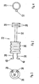
- Fig. 1
- eine Seitenansicht des Instruments in zerlegtem Zustand,
- Fig. 2
- eine gegenüber
Figur 1 um 90° gedrehte Seitenansicht des Griffteils, - Fig. 3
- eine axiale Stirnansicht auf das in
Figur 2 linke proximale Ende des Griffteils, - Fig. 4
- eine axiale Stirnansicht auf das in
Figur 2 rechte distale Ende des Griffteils, - Fig. 5
- eine Seitenansicht des Instruments mit eingesetzter Spritze,
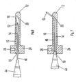
- Fig. 6
- einen Axialschnitt durch das Führungsrohr mit zurückgezogener Kanüle und
- Fig. 7
- einen
Figur 6 entsprechenden Axialschnitt mit distal vorgeschobener Kanüle. - Das medizinische Instrument weist ein Führungsrohr 10 auf, welches an seinem distalen Ende 12 geschlossen ist und eine stumpfe abgerundete Spitze aufweist, die gegebenenfalls auch leicht konisch ausgebildet sein kann. Das innere Lumen des Führungsrohres 10 bildet einen Führungskanal 14 und erweitet sich an dem offenen proximalen Ende zu einem Einführkonus 16. Distal ist der Führungskanal 14 zu einer seitlich in der Wandung des Führungsrohres 10 ausgebildeten Öffnung 18 geführt. Die Öffnung 18 befindet sich hinter dem sich verjüngenden distalen Ende 12 des Führungsrohres 10 in dessen Zylindermantelfläche. Im Inneren des Führungsrohres 10 ist eine Ablenkeinrichtung 20 ausgebildet, die in Form einer keilförmigen Schräge oder einer bogenförmig gerundeten Rampe einen stufenlosen Übergang des koaxialen Führungskanals 14 in die seitliche Öffnung 18 bildet. Das Führungsrohr 10 ist vorzugsweise aus Edelstahl gefertigt, kann gegebenenfalls aber auch aus einem geeigneten Kunststoff hergestellt werden.
- Das Führungsrohr 10 ist drehbar und lösbar an einem Griffteil 22 angebracht. Hierzu weist das proximale Ende des Führungsrohres 10 einen Außenbund 24 auf, der einen gegenüber dem kreisförmigen Querschnitt des Führungsrohres 10 im Durchmesser vergrößerten kreisförmigen Querschnitt aufweist. Der Außenbund 24 ist vorzugsweise einstückig an dem Führungsrohr 10 angeformt. In die zylindrische Außenmantelfläche des Außenbundes 24 ist eine radiale Sackbohrung 26 mit einem Innengewinde eingearbeitet. Der Außenbund 24 wird in einen Lagerring 28 des Griffteils 22 eingesetzt. Der Innendurchmesser des Lagerrings 28 entspricht dem Außendurchmesser des Außenbundes 24, so dass der Außenbund 24 in dem Lagerring 28 drehbar geführt gelagert ist. Die axiale Länge des Außenbundes 24 entspricht der axialen Länge des Lagerringes 28. Der Lagerring 28 weist einen radial durchgehenden und in Umfangsrichtung verlaufenden Umfangsschlitz 30 auf, der sich über nahezu 360° des Umfangs des Außenbundes 24 erstreckt. In einfacher Weise kann der Umfangsschlitz 30 dadurch hergestellt werden, dass der Lagerring 28 aus zwei um die Breite des Umfangsschlitzes 30 axial beabstandeten Einzelringen zusammengesetzt ist, die durch einen axialen Steg 32 in einem engen Winkelabschnitt miteinander verbunden sind. Der Außenbund 24 wird axial in den Lagerring 28 eingeschoben, worauf sich die Sackbohrung 26 in dem axialen Bereich des Umfangsschlitzes 30 befindet. Dann wird ein als Betätigungshebel dienender radialer Stift 34 durch den Umfangsschlitz 30 eingesetzt und in die Sackbohrung 26 eingeschraubt. Der Stift 34 ragt radial über den Lagerring 28 hinaus, so dass der Stift 34 leicht erfasst werden kann, um den Außenbund 24 und damit das Führungsrohr 10 gegenüber dem Lagerring 28 und damit dem Griffteil 22 zu verdrehen. Eine Drehung des Führungsrohres 10 ist damit um einen Winkel möglich, der dem Umfangswinkel des Umfangsschlitzes 30 entspricht, d. h. um einen Winkel von nahezu 360°. Die Sackbohrung 26 und damit der Stift 34 sind vorzugsweise in der selben Winkelposition des Führungsrohres 10 angeordnet, in welcher sich die Öffnung 18 befindet. Der Stift 34 zeigt somit auch die Winkelstellung der Öffnung 18 in Bezug auf das Griffteil 22 an.
- Der in die Sackbohrung 26 eingeschraubte Stift 34 hält den Außenbund 24 und damit das Führungsrohr 10 axial in dem Lagerring 28 und damit an dem Griffteil 22. Durch Herausdrehen des Stiftes 34 aus der Sackbohrung 26 kann das Führungsrohr 10 wieder von dem Griffteil 22 getrennt werden.
- Das Griffteil 22 weist weiter eine Aufnahme 36 auf, die als Handgriff ausgebildet ist und zum Führen des Instruments dient. Die Aufnahme 36 hat die Form eines länglichen hohlen Kreiszylinders und weist an ihrem Außenumfang Umfangsrillen auf, die die Griffigkeit der Aufnahme 36 als Handgriff begünstigen. Am distalen Ende der Aufnahme 36 ist der achsparallele Steg 32 angebracht, der an seinem der Aufnahme 36 entgegengesetzten distalen Ende den Lagerring 28 bzw. die zwei den Lagerring 28 bildenden Einzelringe trägt. Am proximalen Ende der Aufnahme 36 sind zwei Anschlagbügel 38 angebracht. Die zwei Anschlagbügel 38 sind im Winkel gegeneinander versetzt an der proximalen Stirnkante der Aufnahme 36 angebracht, verlaufen von der Aufnahme 36 achsparallel in proximale Richtung und sind an ihrem freien proximalen Ende rechtwinklig nach innen abgebogen, um jeweils einen kurzen Anschlag 40 zu bilden.
- Wird das Instrument zum Injizieren verwendet, so wird in das Instrument eine Injektionsspritze eingesetzt, insbesondere eine handelsübliche Spritze, z. B. eine Einmal-Spritze. Die Spritze weist einen Zylinder 42 auf, an dessen distalen Kanülenansatz 44 eine Kanüle 46 angesetzt wird. Am proximalen Ende des Zylinders 42 ist ein seitlich abstehender Flansch 48 angeformt. In dem Zylinder 42 ist ein Kolben 50 verschiebbar.
- Die Spritze wird mit aufgesetzter Kanüle 46 vom proximalen Ende durch die Aufnahme 36 in das Instrument eingeführt. Die Kanüle 46 gelangt dabei begünstigt durch den Einführkonus 16 in den Führungskanal 14 des Führungsrohres 10. Der Zylinder 42 der Spritze wird koaxial in der Aufnahme 36 aufgenommen. Die Spritze wird soweit in das Instrument eingeführt, bis sich der Flansch 48 am proximalen Ende des Zylinders 42 zwischen dem proximalen Ende der Aufnahme 36 und den Anschlägen 40 der Anschlagbügel 38 befindet. Die Anschläge 40 greifen dabei beiderseits des Kolbens 50 über den Flansch 48.
- Die axialen Längenabmessungen des Instruments sind auf die axialen Längenabmessungen der Spritze, d. h. insbesondere des Zylinders 42 und der Kanüle 46, so abgestimmt, dass sich die distale Spitze 52 der Kanüle 46 im Inneren des Führungskanals 14 hinter der Ablenkeinrichtung 20 befindet, wie
Figur 6 zeigt, wenn der Zylinder 42 mit seinem Flansch 48 an den Anschlägen 40 der Anschlagbügel 38 anliegt. Da die scharfe distale Spitze 52 der Kanüle 46 im Inneren des Führungsrohres 10 liegt, kann das Führungsrohr in den Körperkanal des Patienten eingeführt werden, ohne dass Verletzungen durch die Kanüle 46 möglich sind. Ist das Führungsrohr 10 axial an der Injektionsstelle platziert, so wird der Zylinder 42 der Spritze distal in der Aufnahme 36 vorgeschoben, bis der Flansch 48 an dem proximalen Ende der Aufnahme 36 anschlägt, wie dies in Figur 5 dargestellt ist. Dabei wird die Kanüle 46 in dem Führungskanal 14 ebenfalls distal vorgeschoben, wobei die scharfe Spitze 52 der Kanüle 46 durch die Ablenkeinrichtung 20 abgelenkt wird und seitlich durch die Öffnung 18 aus dem Führungsrohr 10 austritt, wie dies inFigur 7 dargestellt ist. Der Anschlag des Flansches 48 an der Aufnahme 36 definiert dadurch auch, wie weit die Spitze 52 der Kanüle 46 aus dem Führungsrohr 10 austritt, wodurch die Einstichtiefe der Kanüle 46 für die Injektion festgelegt ist. Bei dieser Injektion hält der behandelnde Arzt das Instrument an der als Handgriff ausgebildeten Aufnahme 36. Das Führungsrohr 10 kann mittels des Stiftes 34 koaxial gegenüber dem Griffteil 22 gedreht werden, so dass der behandelnde Arzt bei festgehaltenem Griffteil 22, d. h. bei definierter axialer Position der Öffnung 18 durch Drehen des Stiftes 34 die Winkelposition der Öffnung 18 festlegen kann und damit die Winkelposition, in welcher die Spitze 52 der Kanüle 46 aus dem Führungsrohr 10 austritt und in die Wand des Körperkanals eindringt. Den Einstichwinkel der Spitze 52 in Bezug auf die Achse des Führungsrohres 10 bestimmt dabei die Ablenkeinrichtung 20. Nach einer Injektion in einer ersten Drehwinkelstellung kann die Spritze wieder bis an die Anschläge 40 zurückgezogen werden, wodurch die Spitze 52 der Kanüle 46 wieder in den Führungskanal 14 hineingezogen wird. Das Führungsrohr 10 kann nun in eine neue Winkelposition gedreht werden, um dann durch erneutes distales Verschieben der Spritze wiederum die Spitze 52 in einer anderen Winkelposition einzustechen und erneut zu injizieren. - Es ist offensichtlich, dass die Aufnahme 36 nicht selbst als Handgriff ausgebildet sein muss. Es ist ebenso möglich, an der Aufnahme 36 einen zusätzlichen radial abstehenden Handgriff anzubringen, z. B. nach Art eines Pistolengriffes. Die Ausbildung der Aufnahme 36 als Handgriff hat den Vorteil, dass das Instrument geringe radiale Abmessungen aufweist, was in vielen Fällen die Handhabung erleichtert.
- Weiter ist es möglich, Rastungen vorzusehen, die ein federndes Einrasten des Führungsrohres 10 gegenüber dem Griffteil 22 in vorgegebenen definierten Drehwinkelpositionen ermöglicht. Dies erleichtert die Drehwinkelpositionierung beim Einstechen der Kanüle 46 in die Wand des Körperkanals. In der Regel ist jedoch die Reibung zwischen dem Außenbund 24 und dem Lagerring 28 ausreichend, um das Führungsrohr 10 in der jeweils gewählten Drehwinkelposition zu halten, wobei sich hierbei der Vorteil einer kontinuierlichen Winkelverstellung ergibt.
-
- 10
- Führungsrohr
- 12
- distales Ende
- 14
- Führungskanal
- 16
- Einführkonus
- 18
- Öffnung
- 20
- Ablenkeinrichtung
- 22
- Griffteil
- 24
- Außenbund
- 26
- Sackbohrung
- 28
- Lagerring
- 30
- Umfangsschlitz
- 32
- Steg
- 34
- Stift
- 36
- Aufnahme
- 38
- Anschlagbügel
- 40
- Anschlag
- 42
- Zylinder
- 44
- Kanülenansatz
- 46
- Kanüle
- 48
- Flansch
- 50
- Kolben
- 52
- Spitze
Claims (16)
- Medizinisches Instrument mit einem Führungsrohr (10), das in einen Körperkanal eines Patienten einführbar ist, wobei das Führungsrohr (10) einen inneren axialen Führungskanal (14) aufweist, der hinter dem geschlossenen distalen Ende (12) des Führungsrohres (10) in eine seitlich am Umfang des Führungsrohres (10) angeordnete Öffnung (18) mündet, so dass eine elastisch biegsame Kanüle (46) proximal in den Führungskanal (14) einführbar ist und beim Vorschieben in dem Führungskanal (14) mit ihrer distalen Spitze (52) gegen die Achse des Führungsrohres (10) abgebogen seitlich durch die Öffnung (18) austritt,
dadurch gekennzeichnet, dass das Führungsrohr (10) mit seinem proximalen Ende um seine Längsachse drehbar in einem Griffteil (22) aufgenommen ist. - Instrument nach Anspruch 1,
dadurch gekennzeichnet, dass das Führungsrohr (10) lösbar in dem Griffteil (22) aufgenommen ist. - Instrument nach Anspruch 1 oder 2,
dadurch gekennzeichnet, dass eine Markierung die jeweilige Drehwinkelposition des Führungsrohres (10) gegenüber dem Griffteil (22) erkennbar macht. - Instrument nach einem der vorhergehenden Ansprüche,
dadurch gekennzeichnet, dass das Führungsrohr (10) an seinem proximalen Ende einen im Wesentlichen radial abstehenden Betätigungshebel (Stift 34) aufweist. - Instrument nach einem der vorhergehenden Ansprüche,
dadurch gekennzeichnet, dass das Führungsrohr (10) an seinem proximalen Ende einen Außenbund (24) aufweist, der in einem Lagerring (28) am distalen Ende des Griffteiles (22) drehbar gelagert ist. - Instrument nach Anspruch 5,
dadurch gekennzeichnet, dass der Lagerring (28) einen Umfangsschlitz (30) aufweist, durch welchen der Betätigungshebel (Stift 34) radial hindurch tritt. - Instrument nach Anspruch 6,
dadurch gekennzeichnet, dass der Betätigungshebel (Stift 34) in den Außenbund (24) lösbar eingesetzt ist. - Instrument nach einem der vorhergehenden Ansprüche,
dadurch gekennzeichnet, dass das Griffteil (22) eine Aufnahme (36) für eine Spritze aufweist, in welcher die Spritze axial bewegbar ist zwischen einer proximalen Position, in welcher sich die distale Spitze (52) ihrer Kanüle (46) zurückgezogen in dem Führungskanal (14) befindet, und einer distalen Position, in welcher die distale Spitze (52) der Kanüle (46) durch die Öffnung (18) aus dem Führungsrohr (10) austritt. - Instrument nach Anspruch 8,
dadurch gekennzeichnet, dass die Aufnahme (36) einen Anschlag aufweist, der die axiale Bewegung der Spritze in distaler Richtung begrenzt. - Instrument nach Anspruch 8 oder 9,
dadurch gekennzeichnet, dass die Aufnahme (36) einen Anschlag (38, 40) aufweist, der die axiale Bewegung der Spritze in proximaler Richtung begrenzt. - Instrument nach einem der Ansprüche 8 bis 10,
dadurch gekennzeichnet, dass das Griffteil (22) eine hohlzylindrische Aufnahme (36) aufweist, die den Zylinder (42) der eingesetzten Spritze koaxial umschließt. - Instrument nach Anspruch 11,
dadurch gekennzeichnet, dass die Aufnahme (36) als Handgriff ausgebildet ist. - Instrument nach Anspruch 11,
dadurch gekennzeichnet, dass an der Aufnahme (36) ein Handgriff angebracht ist. - Instrument nach einem der Ansprüche 5 bis 13,
dadurch gekennzeichnet, dass der Lagerring (28) an der Aufnahme (36) befestigt ist. - Instrument nach einem der Ansprüche 9 bis 14,
dadurch gekennzeichnet, dass das proximale Ende der Aufnahme (36) den distalen Anschlag für einen Flansch (48) der Spritze bildet. - Instrument nach einem der Ansprüche 10 bis 15,
dadurch gekennzeichnet, dass an der Aufnahme (36) ein proximal abstehender Anschlag (38, 40) für den Flansch (48) der Spritze als proximaler Anschlag angebracht ist.
Applications Claiming Priority (2)
| Application Number | Priority Date | Filing Date | Title |
|---|---|---|---|
| DE200510044468 DE102005044468A1 (de) | 2005-09-16 | 2005-09-16 | Medizinisches Instrument |
| PCT/EP2006/008856 WO2007031264A1 (de) | 2005-09-16 | 2006-09-12 | Medizinisches instrument |
Publications (3)
| Publication Number | Publication Date |
|---|---|
| EP1924313A1 EP1924313A1 (de) | 2008-05-28 |
| EP1924313B1 true EP1924313B1 (de) | 2012-03-07 |
| EP1924313B8 EP1924313B8 (de) | 2012-04-25 |
Family
ID=42667505
Family Applications (1)
| Application Number | Title | Priority Date | Filing Date |
|---|---|---|---|
| EP06805690A Not-in-force EP1924313B8 (de) | 2005-09-16 | 2006-09-12 | Medizinisches instrument |
Country Status (4)
| Country | Link |
|---|---|
| US (1) | US8394063B2 (de) |
| EP (1) | EP1924313B8 (de) |
| CN (1) | CN101272819B (de) |
| AT (1) | ATE548067T1 (de) |
Families Citing this family (12)
| Publication number | Priority date | Publication date | Assignee | Title |
|---|---|---|---|---|
| US20110213214A1 (en) * | 2010-02-26 | 2011-09-01 | Nellcor Puritan Bennett Llc | Mechanically deployable tracheal tube sensor |
| US9414816B2 (en) | 2011-06-23 | 2016-08-16 | Devicor Medical Products, Inc. | Introducer for biopsy device |
| JP2015523172A (ja) * | 2012-07-27 | 2015-08-13 | ザ リージェンツ オブ ザ ユニバーシティ オブ カリフォルニア | 微量注入カテーテル |
| EP3010574B1 (de) * | 2013-06-17 | 2019-12-18 | Alcyone Lifesciences, Inc. | Vorrichtungen zum schutz von katheterspitzen und stereotaktische befestigungen für mikrokatheter |
| CN106456213B (zh) * | 2014-06-09 | 2019-04-12 | 库克医药技术有限责任公司 | 用于基准物部署的螺钉驱动式手柄及系统 |
| US10028769B2 (en) | 2014-11-06 | 2018-07-24 | Sheryl A ROSS | Gynocological cervical Os instrument |
| DE102016125556A1 (de) * | 2016-12-23 | 2018-06-28 | Georg-August-Universität Göttingen Stiftung Öffentlichen Rechts, Universitätsmedizin | Saugerspitze zum schonenden Absaugen von Blut aus Operationsfeldern |
| DE102017010033A1 (de) * | 2017-10-27 | 2019-05-02 | Joimax Gmbh | Medizinische Vorrichtung |
| WO2019212626A1 (en) * | 2018-04-30 | 2019-11-07 | Boston Scientific Scimed, Inc. | Ramped biopsy needle device |
| CN113056301B (zh) * | 2018-09-28 | 2024-03-12 | 威蓝诺血管股份有限公司 | 用于通过封闭系统静脉内导管进行抽血的装置和方法 |
| CN115591089A (zh) * | 2021-07-09 | 2023-01-13 | 陈韦弘(Tw) | 腔体探测注射复合装置 |
| CN117159900B (zh) * | 2023-10-10 | 2024-02-02 | 中国医学科学院北京协和医院 | 一种放疗插植针弯曲导管 |
Family Cites Families (22)
| Publication number | Priority date | Publication date | Assignee | Title |
|---|---|---|---|---|
| US2907327A (en) * | 1957-02-08 | 1959-10-06 | Pfizer & Co C | Pellet implanter |
| US4182326A (en) | 1977-08-26 | 1980-01-08 | Ims Limited | Laryngotracheal syringe |
| DE3115192C2 (de) | 1981-04-15 | 1983-05-19 | Christian Prof. Dr.med. 2400 Lübeck Krüger | Medizinisches Instrument |
| US4451252A (en) | 1981-07-24 | 1984-05-29 | Vas-Cath Of Canada Limited | Cannula |
| DE3310870A1 (de) | 1982-04-01 | 1983-10-06 | Krueger Christian | Medizinisches instrument |
| US5370675A (en) * | 1992-08-12 | 1994-12-06 | Vidamed, Inc. | Medical probe device and method |
| US4963147A (en) * | 1987-09-18 | 1990-10-16 | John M. Agee | Surgical instrument |
| MX9300607A (es) | 1992-02-06 | 1993-10-01 | American Med Syst | Aparato y metodo para tratamiento intersticial. |
| US5320602A (en) | 1993-05-14 | 1994-06-14 | Wilson-Cook Medical, Inc. | Peel-away endoscopic retrograde cholangio pancreatography catheter and a method for using the same |
| US5360416A (en) * | 1993-09-30 | 1994-11-01 | Sherwood Medical Company | Thin-walled anesthesia needles |
| CN2197991Y (zh) * | 1993-12-11 | 1995-05-24 | 张良元 | 麻醉注射器 |
| FR2747312B1 (fr) | 1996-04-12 | 1998-09-18 | Prodimed | Dispositif a canule hypodermique souple |
| US6447484B1 (en) | 1997-01-09 | 2002-09-10 | Medtronic, Inc. | Flexible disc obturator for a cannula assembly |
| DE19750090B4 (de) | 1997-11-12 | 2011-11-03 | Transcodent GmbH & Co. KG | Kanüle für einen Luer- oder Luerlockanschluß |
| WO2001006911A1 (de) | 1999-07-26 | 2001-02-01 | Karl Storz Gmbh & Co. Kg | Befestigungselement für ein medizinisches instrument und derartiges medizinisches instrument |
| DE10042606A1 (de) | 2000-08-30 | 2001-08-16 | Siemens Ag | Medizinisches Gerät |
| US6758824B1 (en) * | 2000-11-06 | 2004-07-06 | Suros Surgical Systems, Inc. | Biopsy apparatus |
| DE10117286A1 (de) | 2001-04-06 | 2002-10-17 | Disetronic Licensing Ag | Weiche Kanüle |
| US6605047B2 (en) * | 2001-09-10 | 2003-08-12 | Vivant Medical, Inc. | Biopsy marker delivery system |
| US6936006B2 (en) | 2002-03-22 | 2005-08-30 | Novo Nordisk, A/S | Atraumatic insertion of a subcutaneous device |
| US20050101909A1 (en) | 2003-11-07 | 2005-05-12 | Cino Rossi | Apparatus for topical innoculation of pharmaceuticals |
| US7150726B2 (en) | 2004-01-23 | 2006-12-19 | Norfolk Medical | Device for subcutaneous infusion of fluids |
-
2006
- 2006-09-12 US US11/991,794 patent/US8394063B2/en active Active
- 2006-09-12 AT AT06805690T patent/ATE548067T1/de active
- 2006-09-12 CN CN2006800342093A patent/CN101272819B/zh not_active Expired - Fee Related
- 2006-09-12 EP EP06805690A patent/EP1924313B8/de not_active Not-in-force
Also Published As
| Publication number | Publication date |
|---|---|
| US20100222744A1 (en) | 2010-09-02 |
| US8394063B2 (en) | 2013-03-12 |
| EP1924313B8 (de) | 2012-04-25 |
| HK1123231A1 (en) | 2009-06-12 |
| ATE548067T1 (de) | 2012-03-15 |
| CN101272819A (zh) | 2008-09-24 |
| CN101272819B (zh) | 2010-09-29 |
| EP1924313A1 (de) | 2008-05-28 |
Similar Documents
| Publication | Publication Date | Title |
|---|---|---|
| WO2007031264A1 (de) | Medizinisches instrument | |
| EP0679408B1 (de) | Vorrichtung zum Einführen eines Katheters in einen Körperhohlraum | |
| EP0949882B1 (de) | Endoskopisches instrument mit schneidwerkzeug | |
| EP2725962B1 (de) | Trokarsystem | |
| EP0406586B1 (de) | Anästhesiebesteck | |
| EP2956071B1 (de) | Set für die periphere nervenblockade | |
| DE19621099C2 (de) | Vorrichtung mit einem Katheter und einer von der Innenseite in die Herzwand einstechbaren Nadel als Hochfrequenzelektrode | |
| DE3403962C2 (de) | ||
| EP2922483B1 (de) | Trokarvorrichtung und deren verwendung | |
| EP0843536B1 (de) | Operationsinstrument | |
| DE2218901B2 (de) | Trokar zur Einführung von Operationsinstrumenten in Körperhöhlen | |
| EP1924313B8 (de) | Medizinisches instrument | |
| DE9114443U1 (de) | Zervix-Stanze | |
| EP1559379A1 (de) | Vorrichtung zum Setzen von Markern in ein Gewebe | |
| DE112016005402T5 (de) | Hülsen zur nadeleinführung | |
| DE102011102686A1 (de) | Anastomosegerät und Verfahren zum Einführen eines Anastomosegerätes in ein Körperlumen | |
| DE102019105198A1 (de) | Katheteranordnung mit versatzvorrichtung zur gewebeprobenahme | |
| DE102005023414B3 (de) | Vorrichtung zur Durchführung einer transseptalen Punktion | |
| DE3345612A1 (de) | Stichsonde fuer perkutane nephroskopie | |
| WO2013135354A2 (de) | Trokarsystem | |
| DE202011101205U1 (de) | Anastomosegerät | |
| DE60119528T2 (de) | Anordnung und Verfahren für das Zusammenwirken mit einem internen Körperorgan | |
| DE102005044468A1 (de) | Medizinisches Instrument | |
| WO1996018429A1 (de) | Kanüle für die gefässpunktion | |
| DE102004063798A1 (de) | Medizinisches Instrument |
Legal Events
| Date | Code | Title | Description |
|---|---|---|---|
| PUAI | Public reference made under article 153(3) epc to a published international application that has entered the european phase |
Free format text: ORIGINAL CODE: 0009012 |
|
| 17P | Request for examination filed |
Effective date: 20080111 |
|
| AK | Designated contracting states |
Kind code of ref document: A1 Designated state(s): AT BE BG CH CY CZ DE DK EE ES FI FR GB GR HU IE IS IT LI LT LU LV MC NL PL PT RO SE SI SK TR |
|
| GRAP | Despatch of communication of intention to grant a patent |
Free format text: ORIGINAL CODE: EPIDOSNIGR1 |
|
| DAX | Request for extension of the european patent (deleted) | ||
| GRAS | Grant fee paid |
Free format text: ORIGINAL CODE: EPIDOSNIGR3 |
|
| GRAA | (expected) grant |
Free format text: ORIGINAL CODE: 0009210 |
|
| AK | Designated contracting states |
Kind code of ref document: B1 Designated state(s): AT BE BG CH CY CZ DE DK EE ES FI FR GB GR HU IE IS IT LI LT LU LV MC NL PL PT RO SE SI SK TR |
|
| REG | Reference to a national code |
Ref country code: GB Ref legal event code: FG4D Free format text: NOT ENGLISH |
|
| RIN1 | Information on inventor provided before grant (corrected) |
Inventor name: BACHMANN, KARL-HEINZ Inventor name: GAISELMANN, THOMAS Inventor name: REIEK, SIEGFRIED |
|
| REG | Reference to a national code |
Ref country code: CH Ref legal event code: EP Ref country code: AT Ref legal event code: REF Ref document number: 548067 Country of ref document: AT Kind code of ref document: T Effective date: 20120315 |
|
| REG | Reference to a national code |
Ref country code: IE Ref legal event code: FG4D Free format text: LANGUAGE OF EP DOCUMENT: GERMAN |
|
| RIN2 | Information on inventor provided after grant (corrected) |
Inventor name: GAISELMANN, THOMAS Inventor name: BACHMANN, KARL-HEINZ Inventor name: RIEK, SIEGFRIED |
|
| REG | Reference to a national code |
Ref country code: DE Ref legal event code: R096 Ref document number: 502006011094 Country of ref document: DE Effective date: 20120503 |
|
| REG | Reference to a national code |
Ref country code: NL Ref legal event code: VDEP Effective date: 20120307 |
|
| PG25 | Lapsed in a contracting state [announced via postgrant information from national office to epo] |
Ref country code: LT Free format text: LAPSE BECAUSE OF FAILURE TO SUBMIT A TRANSLATION OF THE DESCRIPTION OR TO PAY THE FEE WITHIN THE PRESCRIBED TIME-LIMIT Effective date: 20120307 Ref country code: NL Free format text: LAPSE BECAUSE OF FAILURE TO SUBMIT A TRANSLATION OF THE DESCRIPTION OR TO PAY THE FEE WITHIN THE PRESCRIBED TIME-LIMIT Effective date: 20120307 |
|
| LTIE | Lt: invalidation of european patent or patent extension |
Effective date: 20120307 |
|
| PG25 | Lapsed in a contracting state [announced via postgrant information from national office to epo] |
Ref country code: LV Free format text: LAPSE BECAUSE OF FAILURE TO SUBMIT A TRANSLATION OF THE DESCRIPTION OR TO PAY THE FEE WITHIN THE PRESCRIBED TIME-LIMIT Effective date: 20120307 Ref country code: GR Free format text: LAPSE BECAUSE OF FAILURE TO SUBMIT A TRANSLATION OF THE DESCRIPTION OR TO PAY THE FEE WITHIN THE PRESCRIBED TIME-LIMIT Effective date: 20120608 Ref country code: FI Free format text: LAPSE BECAUSE OF FAILURE TO SUBMIT A TRANSLATION OF THE DESCRIPTION OR TO PAY THE FEE WITHIN THE PRESCRIBED TIME-LIMIT Effective date: 20120307 |
|
| PG25 | Lapsed in a contracting state [announced via postgrant information from national office to epo] |
Ref country code: CY Free format text: LAPSE BECAUSE OF FAILURE TO SUBMIT A TRANSLATION OF THE DESCRIPTION OR TO PAY THE FEE WITHIN THE PRESCRIBED TIME-LIMIT Effective date: 20120307 |
|
| PG25 | Lapsed in a contracting state [announced via postgrant information from national office to epo] |
Ref country code: EE Free format text: LAPSE BECAUSE OF FAILURE TO SUBMIT A TRANSLATION OF THE DESCRIPTION OR TO PAY THE FEE WITHIN THE PRESCRIBED TIME-LIMIT Effective date: 20120307 Ref country code: PL Free format text: LAPSE BECAUSE OF FAILURE TO SUBMIT A TRANSLATION OF THE DESCRIPTION OR TO PAY THE FEE WITHIN THE PRESCRIBED TIME-LIMIT Effective date: 20120307 Ref country code: SI Free format text: LAPSE BECAUSE OF FAILURE TO SUBMIT A TRANSLATION OF THE DESCRIPTION OR TO PAY THE FEE WITHIN THE PRESCRIBED TIME-LIMIT Effective date: 20120307 Ref country code: IS Free format text: LAPSE BECAUSE OF FAILURE TO SUBMIT A TRANSLATION OF THE DESCRIPTION OR TO PAY THE FEE WITHIN THE PRESCRIBED TIME-LIMIT Effective date: 20120707 Ref country code: SE Free format text: LAPSE BECAUSE OF FAILURE TO SUBMIT A TRANSLATION OF THE DESCRIPTION OR TO PAY THE FEE WITHIN THE PRESCRIBED TIME-LIMIT Effective date: 20120307 Ref country code: RO Free format text: LAPSE BECAUSE OF FAILURE TO SUBMIT A TRANSLATION OF THE DESCRIPTION OR TO PAY THE FEE WITHIN THE PRESCRIBED TIME-LIMIT Effective date: 20120307 Ref country code: CZ Free format text: LAPSE BECAUSE OF FAILURE TO SUBMIT A TRANSLATION OF THE DESCRIPTION OR TO PAY THE FEE WITHIN THE PRESCRIBED TIME-LIMIT Effective date: 20120307 |
|
| PG25 | Lapsed in a contracting state [announced via postgrant information from national office to epo] |
Ref country code: PT Free format text: LAPSE BECAUSE OF FAILURE TO SUBMIT A TRANSLATION OF THE DESCRIPTION OR TO PAY THE FEE WITHIN THE PRESCRIBED TIME-LIMIT Effective date: 20120709 Ref country code: SK Free format text: LAPSE BECAUSE OF FAILURE TO SUBMIT A TRANSLATION OF THE DESCRIPTION OR TO PAY THE FEE WITHIN THE PRESCRIBED TIME-LIMIT Effective date: 20120307 |
|
| PLBE | No opposition filed within time limit |
Free format text: ORIGINAL CODE: 0009261 |
|
| STAA | Information on the status of an ep patent application or granted ep patent |
Free format text: STATUS: NO OPPOSITION FILED WITHIN TIME LIMIT |
|
| PG25 | Lapsed in a contracting state [announced via postgrant information from national office to epo] |
Ref country code: DK Free format text: LAPSE BECAUSE OF FAILURE TO SUBMIT A TRANSLATION OF THE DESCRIPTION OR TO PAY THE FEE WITHIN THE PRESCRIBED TIME-LIMIT Effective date: 20120307 |
|
| 26N | No opposition filed |
Effective date: 20121210 |
|
| PG25 | Lapsed in a contracting state [announced via postgrant information from national office to epo] |
Ref country code: IT Free format text: LAPSE BECAUSE OF FAILURE TO SUBMIT A TRANSLATION OF THE DESCRIPTION OR TO PAY THE FEE WITHIN THE PRESCRIBED TIME-LIMIT Effective date: 20120307 |
|
| BERE | Be: lapsed |
Owner name: BACHMANN, KARL-HEINZ Effective date: 20120930 Owner name: RIEK, SIEGFRIED, DR. MED. Effective date: 20120930 Owner name: GAISELMANN, THOMAS Effective date: 20120930 |
|
| REG | Reference to a national code |
Ref country code: DE Ref legal event code: R097 Ref document number: 502006011094 Country of ref document: DE Effective date: 20121210 |
|
| PG25 | Lapsed in a contracting state [announced via postgrant information from national office to epo] |
Ref country code: MC Free format text: LAPSE BECAUSE OF NON-PAYMENT OF DUE FEES Effective date: 20120930 Ref country code: ES Free format text: LAPSE BECAUSE OF FAILURE TO SUBMIT A TRANSLATION OF THE DESCRIPTION OR TO PAY THE FEE WITHIN THE PRESCRIBED TIME-LIMIT Effective date: 20120618 |
|
| REG | Reference to a national code |
Ref country code: CH Ref legal event code: PL |
|
| GBPC | Gb: european patent ceased through non-payment of renewal fee |
Effective date: 20120912 |
|
| REG | Reference to a national code |
Ref country code: IE Ref legal event code: MM4A |
|
| REG | Reference to a national code |
Ref country code: FR Ref legal event code: ST Effective date: 20130531 |
|
| PG25 | Lapsed in a contracting state [announced via postgrant information from national office to epo] |
Ref country code: IE Free format text: LAPSE BECAUSE OF NON-PAYMENT OF DUE FEES Effective date: 20120912 Ref country code: BG Free format text: LAPSE BECAUSE OF FAILURE TO SUBMIT A TRANSLATION OF THE DESCRIPTION OR TO PAY THE FEE WITHIN THE PRESCRIBED TIME-LIMIT Effective date: 20120607 Ref country code: CH Free format text: LAPSE BECAUSE OF NON-PAYMENT OF DUE FEES Effective date: 20120930 Ref country code: GB Free format text: LAPSE BECAUSE OF NON-PAYMENT OF DUE FEES Effective date: 20120912 Ref country code: BE Free format text: LAPSE BECAUSE OF NON-PAYMENT OF DUE FEES Effective date: 20120930 Ref country code: LI Free format text: LAPSE BECAUSE OF NON-PAYMENT OF DUE FEES Effective date: 20120930 |
|
| PG25 | Lapsed in a contracting state [announced via postgrant information from national office to epo] |
Ref country code: FR Free format text: LAPSE BECAUSE OF NON-PAYMENT OF DUE FEES Effective date: 20121001 |
|
| REG | Reference to a national code |
Ref country code: AT Ref legal event code: MM01 Ref document number: 548067 Country of ref document: AT Kind code of ref document: T Effective date: 20120912 |
|
| PG25 | Lapsed in a contracting state [announced via postgrant information from national office to epo] |
Ref country code: AT Free format text: LAPSE BECAUSE OF NON-PAYMENT OF DUE FEES Effective date: 20120912 |
|
| PG25 | Lapsed in a contracting state [announced via postgrant information from national office to epo] |
Ref country code: TR Free format text: LAPSE BECAUSE OF FAILURE TO SUBMIT A TRANSLATION OF THE DESCRIPTION OR TO PAY THE FEE WITHIN THE PRESCRIBED TIME-LIMIT Effective date: 20120307 |
|
| PG25 | Lapsed in a contracting state [announced via postgrant information from national office to epo] |
Ref country code: LU Free format text: LAPSE BECAUSE OF NON-PAYMENT OF DUE FEES Effective date: 20120912 |
|
| PG25 | Lapsed in a contracting state [announced via postgrant information from national office to epo] |
Ref country code: HU Free format text: LAPSE BECAUSE OF FAILURE TO SUBMIT A TRANSLATION OF THE DESCRIPTION OR TO PAY THE FEE WITHIN THE PRESCRIBED TIME-LIMIT Effective date: 20060912 |
|
| PGFP | Annual fee paid to national office [announced via postgrant information from national office to epo] |
Ref country code: DE Payment date: 20161027 Year of fee payment: 11 |
|
| REG | Reference to a national code |
Ref country code: DE Ref legal event code: R119 Ref document number: 502006011094 Country of ref document: DE |
|
| PG25 | Lapsed in a contracting state [announced via postgrant information from national office to epo] |
Ref country code: DE Free format text: LAPSE BECAUSE OF NON-PAYMENT OF DUE FEES Effective date: 20180404 |