EP1924409B1 - Dispositif pour faire pivoter des objets - Google Patents
Dispositif pour faire pivoter des objets Download PDFInfo
- Publication number
- EP1924409B1 EP1924409B1 EP06775764A EP06775764A EP1924409B1 EP 1924409 B1 EP1924409 B1 EP 1924409B1 EP 06775764 A EP06775764 A EP 06775764A EP 06775764 A EP06775764 A EP 06775764A EP 1924409 B1 EP1924409 B1 EP 1924409B1
- Authority
- EP
- European Patent Office
- Prior art keywords
- coupler
- crank
- revolute joint
- guide
- coupling
- Prior art date
- Legal status (The legal status is an assumption and is not a legal conclusion. Google has not performed a legal analysis and makes no representation as to the accuracy of the status listed.)
- Active
Links
Images



Classifications
-
- B—PERFORMING OPERATIONS; TRANSPORTING
- B25—HAND TOOLS; PORTABLE POWER-DRIVEN TOOLS; MANIPULATORS
- B25J—MANIPULATORS; CHAMBERS PROVIDED WITH MANIPULATION DEVICES
- B25J9/00—Program-controlled manipulators
- B25J9/02—Program-controlled manipulators characterised by movement of the arms, e.g. cartesian coordinate type
- B25J9/04—Program-controlled manipulators characterised by movement of the arms, e.g. cartesian coordinate type by rotating at least one arm, excluding the head movement itself, e.g. cylindrical coordinate type or polar coordinate type
-
- B—PERFORMING OPERATIONS; TRANSPORTING
- B25—HAND TOOLS; PORTABLE POWER-DRIVEN TOOLS; MANIPULATORS
- B25J—MANIPULATORS; CHAMBERS PROVIDED WITH MANIPULATION DEVICES
- B25J18/00—Arms
- B25J18/007—Arms the end effector rotating around a fixed point
-
- B—PERFORMING OPERATIONS; TRANSPORTING
- B25—HAND TOOLS; PORTABLE POWER-DRIVEN TOOLS; MANIPULATORS
- B25J—MANIPULATORS; CHAMBERS PROVIDED WITH MANIPULATION DEVICES
- B25J9/00—Program-controlled manipulators
- B25J9/10—Program-controlled manipulators characterised by positioning means for manipulator elements
- B25J9/106—Program-controlled manipulators characterised by positioning means for manipulator elements with articulated links
-
- F—MECHANICAL ENGINEERING; LIGHTING; HEATING; WEAPONS; BLASTING
- F16—ENGINEERING ELEMENTS AND UNITS; GENERAL MEASURES FOR PRODUCING AND MAINTAINING EFFECTIVE FUNCTIONING OF MACHINES OR INSTALLATIONS; THERMAL INSULATION IN GENERAL
- F16H—GEARING
- F16H37/00—Combinations of mechanical gearings, not provided for in groups F16H1/00 - F16H35/00
- F16H37/12—Gearings comprising primarily toothed or friction gearing, links or levers, and cams, or members of at least two of these types
-
- Y—GENERAL TAGGING OF NEW TECHNOLOGICAL DEVELOPMENTS; GENERAL TAGGING OF CROSS-SECTIONAL TECHNOLOGIES SPANNING OVER SEVERAL SECTIONS OF THE IPC; TECHNICAL SUBJECTS COVERED BY FORMER USPC CROSS-REFERENCE ART COLLECTIONS [XRACs] AND DIGESTS
- Y10—TECHNICAL SUBJECTS COVERED BY FORMER USPC
- Y10T—TECHNICAL SUBJECTS COVERED BY FORMER US CLASSIFICATION
- Y10T74/00—Machine element or mechanism
- Y10T74/20—Control lever and linkage systems
- Y10T74/20207—Multiple controlling elements for single controlled element
- Y10T74/20305—Robotic arm
- Y10T74/20329—Joint between elements
-
- Y—GENERAL TAGGING OF NEW TECHNOLOGICAL DEVELOPMENTS; GENERAL TAGGING OF CROSS-SECTIONAL TECHNOLOGIES SPANNING OVER SEVERAL SECTIONS OF THE IPC; TECHNICAL SUBJECTS COVERED BY FORMER USPC CROSS-REFERENCE ART COLLECTIONS [XRACs] AND DIGESTS
- Y10—TECHNICAL SUBJECTS COVERED BY FORMER USPC
- Y10T—TECHNICAL SUBJECTS COVERED BY FORMER US CLASSIFICATION
- Y10T74/00—Machine element or mechanism
- Y10T74/20—Control lever and linkage systems
- Y10T74/20207—Multiple controlling elements for single controlled element
- Y10T74/20305—Robotic arm
- Y10T74/20329—Joint between elements
- Y10T74/20335—Wrist
-
- Y—GENERAL TAGGING OF NEW TECHNOLOGICAL DEVELOPMENTS; GENERAL TAGGING OF CROSS-SECTIONAL TECHNOLOGIES SPANNING OVER SEVERAL SECTIONS OF THE IPC; TECHNICAL SUBJECTS COVERED BY FORMER USPC CROSS-REFERENCE ART COLLECTIONS [XRACs] AND DIGESTS
- Y10—TECHNICAL SUBJECTS COVERED BY FORMER USPC
- Y10T—TECHNICAL SUBJECTS COVERED BY FORMER US CLASSIFICATION
- Y10T74/00—Machine element or mechanism
- Y10T74/20—Control lever and linkage systems
- Y10T74/20207—Multiple controlling elements for single controlled element
- Y10T74/20341—Power elements as controlling elements
- Y10T74/20354—Planar surface with orthogonal movement only
Definitions
- the invention relates to a device for pivoting objects, wherein the objects can be essentially tools or even a camera, with a larger pivoting range, as usual in conventional technical solutions.
- tool pivoting devices are used in many fields of technology. If these devices pivot the tool tip about a fixed point, the tool tip remains spatially fixed during a change in orientation, which may be desirable for many reasons.
- Typical applications can be found in robotics as a robot wrist.
- a robotic wrist is a device for changing the orientation of the guided by the robot tool, for. B. a drill or milling cutter.
- a change of orientation of the tool requires no change in the spatial position of the wrist.
- An enlargement of the robot working space, an improvement of the positioning accuracy and the possibility of a very rapid change of orientation are positive consequences of such an effective principle.
- FR 2460762 A1 also discloses an apparatus for pivoting a work tool about a fixed point with a parallel crank mechanism.
- a similar solution describes US 5697939 A , This also uses a parallel crank - referred to as a parallelogram mechanism - for guiding and above all fixation of a surgical instrument.
- a parallel crank mechanism is used and it is realized the pivoting about the axis perpendicular to the pivot axis of the parallel crank axis with a frame-close hinge.
- a technical solution for scribing is after DE 3545008 A1 explained.
- a bow guide which comprises a quarter circle, is connected to a hinge so that the axis of rotation and the center of the axis of rotation intersect and a tool can be pivoted freely around this point of intersection in the region of a hemisphere.
- All technical solutions with bow guides have specific disadvantages. Sheet guiding elements are heavy, costly precision components and they claim their full range of motion as a collision space. The range of motion is naturally limited.
- a robot wrist for pivoting a tool around a fixed point is in DE 3211688 A1 specified what a so-called double parallel guide is used. Again, comparatively many limbs and joints are required. Low rigidity, in particular perpendicular to the plane of movement of the parallelogram is the Episode. The large number of hinges in the device makes their play-free mobility difficult. The range of motion is limited by the so-called dead spots of the mechanism to about 120 °.
- the drive of the device should be done exclusively with one (a single) rotary or optionally a translational drive movement.
- it is the object of the invention to achieve an unusually high rigidity of the device in the direction of the spatially fixed axis by the path of the power flow should be made short.
- the swivel range of the object should be up to 360 ° so that the object can rotate freely around the virtual, space-fixed axis.
- cross sliding elements which carry the object to be pivoted. Due to the cross slide elements, which firstly between the frame and the first coupling member, referred to as a carrier coupling and continue between the carrying coupling and the second coupling member, referred to as a guide coupling, the coupling members are guided parallel and at a constant distance from the frame.
- the cross slide elements each consist of two, preferably at right angles to each other on a cross plate arranged linear guides. It should first be noted that due to the two cross slide elements, the carrying coupling and the guide coupling can move freely in two dimensions compared to the frame.
- the directional movement of the coupling links is to be set out, which is required so that the problem can be solved, namely that the object can be pivoted outside the device to a virtual, solid axis.
- the movement of the coupling links is predetermined by a guide member, which kinematically is a crank. (Therefore, the term “crank” is used in the future.)
- the crank is mounted fixed to the frame at one end and is driven on the frame side, for example by an electric motor flanged to the frame.
- the crank carries a pivot pin, which forms the one part of the drive-side support coupling pivot joint and connects the crank with the bearing coupling pivotally.
- the pivot pin as part of the Tragekoppelmosgelenks passes through the support coupling and is rigidly connected at its end facing away from the crank with a crank extension, which is connected at its end to the drive-side guide coupling pivot of the guide coupling.
- the crank moves the drive-side support coupling pivot and the drive-side guide coupling pivot along concentric, but not identical circular paths.
- Each coupling member has at the same distance from the support coupling rotary joint and the guide coupling rotary joint another rotary joint, via which the coupling members are interconnected with an output member.
- this output member describes a circular pivot about a virtual, space-fixed axis, which represents itself as a rotation axis between frame and crank displaced around the vector between the two rotary joints of the coupling links.
- the object to be pivoted such as a tool
- TCP Tool Center Point
- JP 2004146714 A Another solution of a holding device for tools in a machine tool is in JP 2004146714 A presented.
- One of three rotating shafts of the device communicates with a base member, with guide rails also attached to the latter.
- movable holding members are connected to the portable objects.
- couplers are connected to the respective other shafts, with motion reversing mechanisms for reversing the rotational motion of the couplers into linear motions of the objects to be moved.
- the rotational movements of the rotating shafts are converted into linear movements of the respective held members. Pivoting objects around space-fixed virtual axes is not possible with this solution.
- the frame is made so wide that a second crank, which corresponds exactly to the previously described crank and is mounted horizontally at the same height on the frame, is driven synchronously with the crank already described.
- the over-determination thus given has an advantageous effect on the stability of the device.
- the further transmission of the movements is carried out analogously as previously described, only with the difference that the required components are made twice on the drive side.
- the device consists only of a coupling member which is connected in the manner already described via a cross-slide member with the frame.
- a rotary joint of this coupling member is connected to a lever which in turn has a connection to the frame with a hinge.
- a second pivot on the coupling member serves as a support for the output member, which in turn carries the flange for the tool.
- On the axis of the lying between the lever and coupling member pivot a first cylindrical pulley of a traction mechanism is arranged such that the cylinder axis coincides with the axis of rotation.
- the output member carries a second disc, which is identical in diameter with the first. Both discs are by a traction device, for. As a toothed belt or a chain connected and guarantee the parallel guidance of the output member to the drive coupling.
- the frame and the constant distance and parallel to the frame guided coupling links should preferably be made flat.
- the cross-slide elements preferably consist of mutually perpendicular and connected to a plate linear guides.
- the angle formed by the axes of the (frame-side, support coupling-side, guide coupling side) first and second linear guide should be as large as possible (90 °).
- the second linear guide can connect the guide coupling with the frame instead of the support coupling.
- the drive of the crank via pinion and drive gear is preferably via a rotary, suitably electric drive.
- a translatory drive would be conceivable.
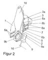
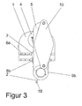
- FIGS. 1-4 It will be on the FIGS. 1-4 directed.
- the distance of the support coupling 5 to the frame 1 is less than the distance of the guide coupling 10.
- To guide the support coupling 5 and the guide coupling 10 serve two Cross slide elements, each consisting of two, arranged at right angles to each other and connected to a plate linear guides.
- the first linear guide 6 b consists of the frame-side rails 6 a of the first linear guide 6 b, which are fixedly connected to the frame 1 and on this linearly movable frame-side carriage of the first linear guide 6 b.
- the cars of the first linear guide 6 b are connected to the first cross plate 7, with the turn also the carrier coupling side carriage 8 b of the first linear guide 6 b are connected.
- the current in the carrier coupling side carriage 8 b of the first linear guide 6 b current carrying coupling rails 8 a of the first linear guide 6 b are connected to the support coupling fifth
- the connection of the carriage with the first cross plate 7 is carried out according to embodiment so that the axis of the frame-side rails 6 a of the first linear guide 6 b and the support coupling rails 8 a of the first linear guide 6 b included angle is 90 °.
- the carrying coupling 5 and the guide coupling 10 are connected to the second linear guide.
- the support coupling side rail of the second linear guide 11 a is connected to the support coupling 5.
- the tie-side Carriage of the second linear guide 11 b move linearly and are connected to the second cross plate 12.
- the guide coupling side carriage of the second linear guide 14b is connected to the second cross plate 12 , in which the guide coupling side rail of the second linear guide 14a is linearly movable and is fixedly connected to the guide coupling 10.
- the angle of the axes of the support coupling side rail of the second linear guide 11 a and the guide coupling side rail of the second linear guide 14 a included angle 90 °.
- the movement of the coupling links is predetermined by the crank 4.
- the crank 4 is mounted fixed to the frame at one end and firmly connected to a drive gear. About a rotary, preferably electric drive 3 with a drive pinion 3a, the drive gear and thus the crank 4 is moved.
- the crank 4 carries a pivot pin 4 b, which forms the one part of the drive-side support coupling pivot 5 a and connects the crank 4 with the support coupling 5 pivotally.
- the pivot pin 4 b leads through the support coupling 5 and is at its end remote from the crank 4 with a crank 4 c rigidly connected, which is connected at its end to the drive-side guide coupling pivot 10 a of the guide coupling 10.
- the crank 4 moves the drive-side support coupling pivot 5a and the drive-side guide coupling pivot 10 a along concentric, but not in identical circular paths.
- the carrying coupling 5 carries a further rotary joint, the driven-side carrying coupling pivot 5 b.
- the pivot distance in the extension plane of the guide coupling 10 and the support coupling 5 must be identical and greater than the joint spacing on the crank extension 4 c.
- the output member 9 describes a circular pivoting movement about the stationary axis 16.
- the joint distance of the crank extension 4 c and on the output lever 9 b must be the same size.
- the blupielle solution is shown when two cranks 4 are used. Movement and power flow correspond to the 1st embodiment.
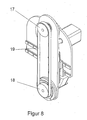
- Embodiment 3 shows a basic solution using a traction mechanism, such as a toothed belt or a chain.
- a traction mechanism such as a toothed belt or a chain.
- the drive-side Buchgetrieberad 17 is attached.
- the output side Buchgetrieberad 18 is mounted instead of the output lever 9 b on the output side support coupling rotary joint 5 b.
- the Switzerlandstoffgetriebecken 17 and 18 have identical diameters. Both Switzerlandstoffgetriebecken 17 and 18 are connected by a pulling means 19.
Landscapes
- Engineering & Computer Science (AREA)
- Mechanical Engineering (AREA)
- Robotics (AREA)
- General Engineering & Computer Science (AREA)
- Manipulator (AREA)
- Rear-View Mirror Devices That Are Mounted On The Exterior Of The Vehicle (AREA)
- Spinning Or Twisting Of Yarns (AREA)
- Multiple-Way Valves (AREA)
- Transmission Devices (AREA)
Claims (7)
- Dispositif servant à faire pivoter des objets en utilisant un bâti (1) et deux éléments de poussée croisés ainsi que deux bielles, notamment une bielle de transmission (5) et une bielle de guidage (10), lesquelles sont déplaçables sur deux dimensions à l'aide des éléments de poussée croisés et de plus un élément de guidage, lequel représente une manivelle (4) du point de vue de la cinématique et un élément d'entraînement (9) sur lequel est disposé l'objet en spécifiant que- la manivelle (4) est logée sur un côté au bâti (1),- que la manivelle (4) est reliée sur l'autre côté par une articulation tournante à la bielle de transmission (5),- que dans le sens axial de la liaison à articulation tournante de la manivelle (4) avec la bielle de transmission (5) se trouve une prolongation rigide de la manivelle (4 c), laquelle est reliée avec une articulation tournante de la bielle de guidage (10 a) côté entraînement manière que la manivelle (4) mette en mouvement l'articulation tournante côté entraînement (5 a) et l'articulation tournante de la bielle de guidage (10 a) le long d'orbites circulaires concentriques et de plus que- la bielle de transmission (5) et la bielle de guidage (10) présentent chacune à la même distance de l'articulation tournante de la bielle de transmission (5 a) côté entraînement et respectivement de l'articulation tournante de la bielle de guidage (10 a) côté entraînement une articulation tournante de la bielle de transmission (5 b) côté entraîné et respectivement une articulation tournante de la bielle de guidage (10 b) côté entraîné- que l'articulation tournante de la bielle de transmission (5 b) côté entraîné et l'articulation tournante de la bielle de guidage (10 b) côté entraîné sont reliées ensemble de manière rotative avec l'élément entraîné (9), qui représente le porte-outil, de sorte que le porte-outil (9) se trouve sur le côté de la bielle de transmission (5) tourné vers le bâti (1) et qu'un maneton à console (9 a) passant à travers la bielle de transmission (5) soit relié fermement à un levier entraîné (9 b) lequel, quant à lui, est relié à l'articulation tournante de la bielle de guidage (10 b) côté entraîné.
- Dispositif selon la revendication 1 caractérisé en ce que sur la même hauteur côté bâti se trouve une deuxième manivelle qui se déplace en synchronisme avec la première manivelle, les éléments côté entraînement en raison de la deuxième manivelle, notamment le pivot (4 b), le prolongement de la manivelle (4 c) l'articulation tournante de la bielle de transmission (5 a) côté entraînement et l'articulation tournante de la bielle de guidage (10 a) côté entraînement étant exécutés en double nombre.
- Dispositif selon la revendication 1 caractérisé en ce que le dispositif n'est constitué que d'un élément de bielle relié au bâti (1) par un élément de poussée croisé, par l'utilisation d'une articulation tournante, cet élément de bielle étant relié à un levier, qui, de son côté, possède avec une articulation tournante une liaison au bâti (1) et une deuxième articulation tournante servant sur l'élément de bielle de logement pour l'élément entraîné (9).
- Dispositif selon les revendications 1 et 3 caractérisé en ce que l'élément de bielle est formé comme engrenage de traction et qu'il y a ainsi un guidage parallèle de l'élément entraîné envers la bielle d'entraînement.
- Dispositif selon les revendications 1 et 2 caractérisé en ce que le bâti (1) et les éléments de bielle (5, 10) menés parallèlement au bâti sont disposés de préférence de manière plane.
- Dispositif selon les revendications 1, 2 et 3 caractérisé en ce que les éléments de poussée croisés sont constitués de guidages linéaires disposés perpendiculairement l'un par rapport à l'autre.
- Dispositif selon les revendications 1, 2 et 3 caractérisé en ce que l'entraînement du dispositif se fait de préférence par un mouvement d'entraînement rotatoire.
Applications Claiming Priority (2)
| Application Number | Priority Date | Filing Date | Title |
|---|---|---|---|
| DE102005041462A DE102005041462B3 (de) | 2005-09-01 | 2005-09-01 | Vorrichtung zum Schwenken von Objekten |
| PCT/DE2006/001318 WO2007025495A2 (fr) | 2005-09-01 | 2006-07-28 | Dispositif pour faire pivoter des objets |
Publications (2)
| Publication Number | Publication Date |
|---|---|
| EP1924409A2 EP1924409A2 (fr) | 2008-05-28 |
| EP1924409B1 true EP1924409B1 (fr) | 2008-10-29 |
Family
ID=37026563
Family Applications (1)
| Application Number | Title | Priority Date | Filing Date |
|---|---|---|---|
| EP06775764A Active EP1924409B1 (fr) | 2005-09-01 | 2006-07-28 | Dispositif pour faire pivoter des objets |
Country Status (7)
| Country | Link |
|---|---|
| US (1) | US8079284B2 (fr) |
| EP (1) | EP1924409B1 (fr) |
| JP (1) | JP4852101B2 (fr) |
| KR (1) | KR100974580B1 (fr) |
| AT (1) | ATE412496T1 (fr) |
| DE (2) | DE102005041462B3 (fr) |
| WO (1) | WO2007025495A2 (fr) |
Families Citing this family (8)
| Publication number | Priority date | Publication date | Assignee | Title |
|---|---|---|---|---|
| DE102007023585B4 (de) * | 2007-05-16 | 2009-08-20 | Esab Cutting Systems Gmbh | Einrichtung und Verfahren zum Einmessen von Schwenkaggregaten, insbesondere an Schneidmaschinen |
| DE102008038103A1 (de) | 2008-08-13 | 2010-02-18 | Esab Cutting Systems Gmbh | Numerisch gesteuerte Werkzeughaltevorrichtung zur Strahlbearbeitung |
| ITTO20120425A1 (it) * | 2012-05-11 | 2013-11-12 | Dalmec Spa | Manipolatore pneumatico bilanciato |
| DE102013205008B4 (de) | 2012-10-19 | 2016-07-28 | Macaso Gmbh | Vorrichtung zur Erzielung vorteilhafter kinematischer Eigenschaften bei der Verschwenkung programmgesteuert bewegter, rotationssymmetrisch wirkender Werkzeuge |
| DE102015111636A1 (de) | 2014-07-23 | 2016-01-28 | SCHWEIßTECHNISCHE LEHR- UND VERSUCHSANSTALT HALLE GMBH | Computergesteuerte Bewegungseinrichtung zur Verbesserung des Ergebnisses eines subtraktiven Bearbeitungsvorgangs |
| CN104260113A (zh) * | 2014-09-22 | 2015-01-07 | 珠海林顺机电有限公司 | 码垛机器人连杆装置 |
| DE102017113234A1 (de) | 2016-06-17 | 2017-12-21 | Macaso Gmbh | Mobile Vorrichtung zur Ausführung von Bearbeitungsaufgaben an großen, plattenförmigen oder gering gekrümmten Bauteilen mit schweißtechnischen Verfahren |
| CN114193507B (zh) * | 2021-12-30 | 2025-11-21 | 上海非夕机器人科技有限公司 | 用于转动关节的编码器模组、转动关节、机器臂和机器人 |
Family Cites Families (17)
| Publication number | Priority date | Publication date | Assignee | Title |
|---|---|---|---|---|
| FR2460762A1 (fr) | 1979-07-12 | 1981-01-30 | Technigaz | Dispositif pour la commande de l'orientation d'un outil ou d'un element analogue par rapport a une piece |
| DE3211688C2 (de) * | 1982-03-30 | 1986-10-09 | Binder, Karl-Franz, 8077 Reichertshofen | Industrie-Roboter für Fertigungs- und/oder Montagezwecke |
| US4551058A (en) * | 1983-07-20 | 1985-11-05 | Robotics, Inc. | Low cost articulating/articulating and rotating wrist mechanism for automatic machine tool and automatic machine tool employing the same |
| DE3545008A1 (de) * | 1985-12-19 | 1987-06-25 | Stiefelmayer Kg C | Haltevorrichtung fuer mess- und/oder anreisswerkzeuge |
| JPS63278674A (ja) | 1987-05-11 | 1988-11-16 | Shinko Electric Co Ltd | 回転中心のオフセツト機構 |
| US5201742A (en) * | 1991-04-16 | 1993-04-13 | Hasson Harrith M | Support jig for a surgical instrument |
| JPH066136B2 (ja) * | 1991-12-25 | 1994-01-26 | 佐原 今朝徳 | 医療用光学機器のスタンド装置 |
| JP3273084B2 (ja) * | 1992-08-20 | 2002-04-08 | オリンパス光学工業株式会社 | 医療器具ホルダ装置 |
| JP3413730B2 (ja) * | 1994-04-21 | 2003-06-09 | ソニー株式会社 | 水平多関節ロボット |
| US5746565A (en) * | 1996-01-22 | 1998-05-05 | Integrated Solutions, Inc. | Robotic wafer handler |
| US7175635B2 (en) * | 2000-03-30 | 2007-02-13 | Siemens Aktiengesellschaft | Medical device with a drive unit for a needle |
| EP1351619A4 (fr) * | 2001-01-16 | 2011-01-05 | Microdexterity Systems Inc | Manipulateur chirurgical |
| JP2003299674A (ja) * | 2002-04-12 | 2003-10-21 | Masasuke Shiraishi | 手術台装置 |
| NL1020396C2 (nl) * | 2002-04-16 | 2003-10-17 | Amc Amsterdam | Manipulator voor een instrument voor minimaal-invasieve chirurgie, alsmede een dergelijk instrument. |
| JP4207530B2 (ja) * | 2002-10-28 | 2009-01-14 | 東京エレクトロン株式会社 | 被処理体の搬送機構 |
| JP4270889B2 (ja) * | 2003-01-15 | 2009-06-03 | オリンパス株式会社 | 医療用器具保持装置 |
| DE202004017526U1 (de) * | 2004-11-12 | 2005-03-31 | Waldorf Technik Gmbh & Co Kg | Translations- und Schwenkvorrichtung |
-
2005
- 2005-09-01 DE DE102005041462A patent/DE102005041462B3/de not_active Expired - Lifetime
-
2006
- 2006-07-28 WO PCT/DE2006/001318 patent/WO2007025495A2/fr not_active Ceased
- 2006-07-28 AT AT06775764T patent/ATE412496T1/de active
- 2006-07-28 US US11/989,705 patent/US8079284B2/en active Active
- 2006-07-28 DE DE502006001961T patent/DE502006001961D1/de active Active
- 2006-07-28 EP EP06775764A patent/EP1924409B1/fr active Active
- 2006-07-28 KR KR1020087005401A patent/KR100974580B1/ko active Active
- 2006-07-28 JP JP2008528323A patent/JP4852101B2/ja active Active
Also Published As
| Publication number | Publication date |
|---|---|
| KR100974580B1 (ko) | 2010-08-06 |
| EP1924409A2 (fr) | 2008-05-28 |
| JP4852101B2 (ja) | 2012-01-11 |
| WO2007025495A2 (fr) | 2007-03-08 |
| US8079284B2 (en) | 2011-12-20 |
| WO2007025495A3 (fr) | 2007-08-09 |
| DE102005041462B3 (de) | 2006-10-12 |
| JP2009506806A (ja) | 2009-02-19 |
| ATE412496T1 (de) | 2008-11-15 |
| KR20080036133A (ko) | 2008-04-24 |
| DE502006001961D1 (de) | 2008-12-11 |
| US20090145256A1 (en) | 2009-06-11 |
Similar Documents
| Publication | Publication Date | Title |
|---|---|---|
| DE102010007631B4 (de) | Parallelroboter mit einem Handgelenkabschnitt mit drei Freiheitsgraden | |
| DE69417229T2 (de) | Chirurgiegerät | |
| DE102009057585B4 (de) | Verfahren zum Kalibrieren eines Roboters | |
| EP3082601B1 (fr) | Appareil à rayons x équipé d'un moyen de réglage | |
| WO2018001742A1 (fr) | Ensemble porte-instrument pour un manipulateur de système robotisé pour interventions chirurgicales | |
| DE602004002281T2 (de) | Vorrichtung zur bewegung und ausrichtung eines objekts im raum und verwendung davon bei schnellbearbeitung | |
| DE60206979T2 (de) | Mehrachsige Handwerkzeugmaschine | |
| EP0812652B1 (fr) | Dispositif pour usiner et/ou monter des pièces | |
| DE102013205008B4 (de) | Vorrichtung zur Erzielung vorteilhafter kinematischer Eigenschaften bei der Verschwenkung programmgesteuert bewegter, rotationssymmetrisch wirkender Werkzeuge | |
| DE19611130A1 (de) | Vorrichtung zur Erzeugung einer definierten Positionierung und Orientierung mindestens einer Plattform | |
| AT502864A2 (de) | Parallelkinematischer roboter | |
| EP0133499A2 (fr) | Mécanisme pour manipulateurs | |
| DE10391447B4 (de) | Hybrider Parallelmanipulator zum Verfahren eines Arbeitskopfes im Raum | |
| DE102012008122B4 (de) | Vorrichtung zur mehrachsigen Orientierung und/oder Positionierung eines Werkzeugs | |
| EP1924409B1 (fr) | Dispositif pour faire pivoter des objets | |
| DE3428748C2 (de) | Getriebekopf für Manipulatoren | |
| DE112006001920B4 (de) | Parallelkinematische Vorrichtung mit Mitteln zur Kompensation der Haltekraft | |
| EP3455036B1 (fr) | Préhenseur de robot pourvu d'un dispositif d'entraînement | |
| WO2023144125A1 (fr) | Robot articulé pour manipuler de grandes charges | |
| EP1658016B1 (fr) | Dispositif support chirurgical | |
| WO2008116524A1 (fr) | Manipulateur | |
| DE3513056A1 (de) | Gelenk-antriebsanordnung | |
| EP2444208B1 (fr) | Dispositif de manipulation | |
| DE10211055B4 (de) | Bewegungs- und/oder Positioniervorrichtung | |
| DE102016215744A1 (de) | Industrieroboter |
Legal Events
| Date | Code | Title | Description |
|---|---|---|---|
| PUAI | Public reference made under article 153(3) epc to a published international application that has entered the european phase |
Free format text: ORIGINAL CODE: 0009012 |
|
| 17P | Request for examination filed |
Effective date: 20071217 |
|
| AK | Designated contracting states |
Kind code of ref document: A2 Designated state(s): AT BE BG CH CY CZ DE DK EE ES FI FR GB GR HU IE IS IT LI LT LU LV MC NL PL PT RO SE SI SK TR |
|
| GRAP | Despatch of communication of intention to grant a patent |
Free format text: ORIGINAL CODE: EPIDOSNIGR1 |
|
| DAX | Request for extension of the european patent (deleted) | ||
| GRAS | Grant fee paid |
Free format text: ORIGINAL CODE: EPIDOSNIGR3 |
|
| GRAA | (expected) grant |
Free format text: ORIGINAL CODE: 0009210 |
|
| AK | Designated contracting states |
Kind code of ref document: B1 Designated state(s): AT BE BG CH CY CZ DE DK EE ES FI FR GB GR HU IE IS IT LI LT LU LV MC NL PL PT RO SE SI SK TR |
|
| REG | Reference to a national code |
Ref country code: GB Ref legal event code: FG4D Free format text: NOT ENGLISH |
|
| REG | Reference to a national code |
Ref country code: CH Ref legal event code: EP |
|
| REG | Reference to a national code |
Ref country code: IE Ref legal event code: FG4D Free format text: LANGUAGE OF EP DOCUMENT: GERMAN |
|
| REF | Corresponds to: |
Ref document number: 502006001961 Country of ref document: DE Date of ref document: 20081211 Kind code of ref document: P |
|
| REG | Reference to a national code |
Ref country code: SE Ref legal event code: TRGR |
|
| LTIE | Lt: invalidation of european patent or patent extension |
Effective date: 20081029 |
|
| PG25 | Lapsed in a contracting state [announced via postgrant information from national office to epo] |
Ref country code: LT Free format text: LAPSE BECAUSE OF FAILURE TO SUBMIT A TRANSLATION OF THE DESCRIPTION OR TO PAY THE FEE WITHIN THE PRESCRIBED TIME-LIMIT Effective date: 20081029 Ref country code: ES Free format text: LAPSE BECAUSE OF FAILURE TO SUBMIT A TRANSLATION OF THE DESCRIPTION OR TO PAY THE FEE WITHIN THE PRESCRIBED TIME-LIMIT Effective date: 20090209 Ref country code: BG Free format text: LAPSE BECAUSE OF FAILURE TO SUBMIT A TRANSLATION OF THE DESCRIPTION OR TO PAY THE FEE WITHIN THE PRESCRIBED TIME-LIMIT Effective date: 20090129 |
|
| PG25 | Lapsed in a contracting state [announced via postgrant information from national office to epo] |
Ref country code: SI Free format text: LAPSE BECAUSE OF FAILURE TO SUBMIT A TRANSLATION OF THE DESCRIPTION OR TO PAY THE FEE WITHIN THE PRESCRIBED TIME-LIMIT Effective date: 20081029 Ref country code: PL Free format text: LAPSE BECAUSE OF FAILURE TO SUBMIT A TRANSLATION OF THE DESCRIPTION OR TO PAY THE FEE WITHIN THE PRESCRIBED TIME-LIMIT Effective date: 20081029 Ref country code: IS Free format text: LAPSE BECAUSE OF FAILURE TO SUBMIT A TRANSLATION OF THE DESCRIPTION OR TO PAY THE FEE WITHIN THE PRESCRIBED TIME-LIMIT Effective date: 20090228 Ref country code: FI Free format text: LAPSE BECAUSE OF FAILURE TO SUBMIT A TRANSLATION OF THE DESCRIPTION OR TO PAY THE FEE WITHIN THE PRESCRIBED TIME-LIMIT Effective date: 20081029 Ref country code: PT Free format text: LAPSE BECAUSE OF FAILURE TO SUBMIT A TRANSLATION OF THE DESCRIPTION OR TO PAY THE FEE WITHIN THE PRESCRIBED TIME-LIMIT Effective date: 20090330 Ref country code: LV Free format text: LAPSE BECAUSE OF FAILURE TO SUBMIT A TRANSLATION OF THE DESCRIPTION OR TO PAY THE FEE WITHIN THE PRESCRIBED TIME-LIMIT Effective date: 20081029 |
|
| REG | Reference to a national code |
Ref country code: IE Ref legal event code: FD4D |
|
| PG25 | Lapsed in a contracting state [announced via postgrant information from national office to epo] |
Ref country code: RO Free format text: LAPSE BECAUSE OF FAILURE TO SUBMIT A TRANSLATION OF THE DESCRIPTION OR TO PAY THE FEE WITHIN THE PRESCRIBED TIME-LIMIT Effective date: 20081029 Ref country code: IE Free format text: LAPSE BECAUSE OF FAILURE TO SUBMIT A TRANSLATION OF THE DESCRIPTION OR TO PAY THE FEE WITHIN THE PRESCRIBED TIME-LIMIT Effective date: 20081029 Ref country code: DK Free format text: LAPSE BECAUSE OF FAILURE TO SUBMIT A TRANSLATION OF THE DESCRIPTION OR TO PAY THE FEE WITHIN THE PRESCRIBED TIME-LIMIT Effective date: 20081029 Ref country code: EE Free format text: LAPSE BECAUSE OF FAILURE TO SUBMIT A TRANSLATION OF THE DESCRIPTION OR TO PAY THE FEE WITHIN THE PRESCRIBED TIME-LIMIT Effective date: 20081029 |
|
| PLBE | No opposition filed within time limit |
Free format text: ORIGINAL CODE: 0009261 |
|
| STAA | Information on the status of an ep patent application or granted ep patent |
Free format text: STATUS: NO OPPOSITION FILED WITHIN TIME LIMIT |
|
| 26N | No opposition filed |
Effective date: 20090730 |
|
| BERE | Be: lapsed |
Owner name: ESAB CUTTING SYSTEMS G.M.B.H. Effective date: 20090731 |
|
| PG25 | Lapsed in a contracting state [announced via postgrant information from national office to epo] |
Ref country code: MC Free format text: LAPSE BECAUSE OF NON-PAYMENT OF DUE FEES Effective date: 20090731 |
|
| PG25 | Lapsed in a contracting state [announced via postgrant information from national office to epo] |
Ref country code: BE Free format text: LAPSE BECAUSE OF NON-PAYMENT OF DUE FEES Effective date: 20090731 |
|
| PG25 | Lapsed in a contracting state [announced via postgrant information from national office to epo] |
Ref country code: GR Free format text: LAPSE BECAUSE OF FAILURE TO SUBMIT A TRANSLATION OF THE DESCRIPTION OR TO PAY THE FEE WITHIN THE PRESCRIBED TIME-LIMIT Effective date: 20090130 |
|
| PGFP | Annual fee paid to national office [announced via postgrant information from national office to epo] |
Ref country code: DE Payment date: 20100723 Year of fee payment: 5 |
|
| REG | Reference to a national code |
Ref country code: CH Ref legal event code: PL |
|
| PG25 | Lapsed in a contracting state [announced via postgrant information from national office to epo] |
Ref country code: LI Free format text: LAPSE BECAUSE OF NON-PAYMENT OF DUE FEES Effective date: 20100731 Ref country code: LU Free format text: LAPSE BECAUSE OF NON-PAYMENT OF DUE FEES Effective date: 20090728 Ref country code: CH Free format text: LAPSE BECAUSE OF NON-PAYMENT OF DUE FEES Effective date: 20100731 |
|
| PG25 | Lapsed in a contracting state [announced via postgrant information from national office to epo] |
Ref country code: HU Free format text: LAPSE BECAUSE OF FAILURE TO SUBMIT A TRANSLATION OF THE DESCRIPTION OR TO PAY THE FEE WITHIN THE PRESCRIBED TIME-LIMIT Effective date: 20090430 |
|
| PG25 | Lapsed in a contracting state [announced via postgrant information from national office to epo] |
Ref country code: TR Free format text: LAPSE BECAUSE OF FAILURE TO SUBMIT A TRANSLATION OF THE DESCRIPTION OR TO PAY THE FEE WITHIN THE PRESCRIBED TIME-LIMIT Effective date: 20081029 |
|
| PG25 | Lapsed in a contracting state [announced via postgrant information from national office to epo] |
Ref country code: CY Free format text: LAPSE BECAUSE OF FAILURE TO SUBMIT A TRANSLATION OF THE DESCRIPTION OR TO PAY THE FEE WITHIN THE PRESCRIBED TIME-LIMIT Effective date: 20081029 |
|
| PG25 | Lapsed in a contracting state [announced via postgrant information from national office to epo] |
Ref country code: DE Free format text: LAPSE BECAUSE OF NON-PAYMENT OF DUE FEES Effective date: 20120201 |
|
| REG | Reference to a national code |
Ref country code: DE Ref legal event code: R119 Ref document number: 502006001961 Country of ref document: DE Effective date: 20120201 |
|
| REG | Reference to a national code |
Ref country code: FR Ref legal event code: PLFP Year of fee payment: 10 |
|
| REG | Reference to a national code |
Ref country code: FR Ref legal event code: PLFP Year of fee payment: 11 |
|
| REG | Reference to a national code |
Ref country code: FR Ref legal event code: PLFP Year of fee payment: 12 |
|
| REG | Reference to a national code |
Ref country code: FR Ref legal event code: PLFP Year of fee payment: 13 |
|
| P01 | Opt-out of the competence of the unified patent court (upc) registered |
Effective date: 20230522 |
|
| PGFP | Annual fee paid to national office [announced via postgrant information from national office to epo] |
Ref country code: SK Payment date: 20250630 Year of fee payment: 20 |
|
| PGFP | Annual fee paid to national office [announced via postgrant information from national office to epo] |
Ref country code: NL Payment date: 20250726 Year of fee payment: 20 |
|
| PGFP | Annual fee paid to national office [announced via postgrant information from national office to epo] |
Ref country code: IT Payment date: 20250721 Year of fee payment: 20 |
|
| PGFP | Annual fee paid to national office [announced via postgrant information from national office to epo] |
Ref country code: GB Payment date: 20250728 Year of fee payment: 20 |
|
| PGFP | Annual fee paid to national office [announced via postgrant information from national office to epo] |
Ref country code: AT Payment date: 20250702 Year of fee payment: 20 Ref country code: FR Payment date: 20250728 Year of fee payment: 20 |
|
| PGFP | Annual fee paid to national office [announced via postgrant information from national office to epo] |
Ref country code: SE Payment date: 20250727 Year of fee payment: 20 |
|
| PGFP | Annual fee paid to national office [announced via postgrant information from national office to epo] |
Ref country code: CZ Payment date: 20250708 Year of fee payment: 20 |