EP1924794B1 - Dispositif de mise au point - Google Patents
Dispositif de mise au point Download PDFInfo
- Publication number
- EP1924794B1 EP1924794B1 EP20060808848 EP06808848A EP1924794B1 EP 1924794 B1 EP1924794 B1 EP 1924794B1 EP 20060808848 EP20060808848 EP 20060808848 EP 06808848 A EP06808848 A EP 06808848A EP 1924794 B1 EP1924794 B1 EP 1924794B1
- Authority
- EP
- European Patent Office
- Prior art keywords
- rotor
- flushing
- rotary seal
- arrangement
- stator
- Prior art date
- Legal status (The legal status is an assumption and is not a legal conclusion. Google has not performed a legal analysis and makes no representation as to the accuracy of the status listed.)
- Not-in-force
Links
Images



Classifications
-
- F—MECHANICAL ENGINEERING; LIGHTING; HEATING; WEAPONS; BLASTING
- F16—ENGINEERING ELEMENTS AND UNITS; GENERAL MEASURES FOR PRODUCING AND MAINTAINING EFFECTIVE FUNCTIONING OF MACHINES OR INSTALLATIONS; THERMAL INSULATION IN GENERAL
- F16K—VALVES; TAPS; COCKS; ACTUATING-FLOATS; DEVICES FOR VENTING OR AERATING
- F16K3/00—Gate valves or sliding valves, i.e. cut-off apparatus with closing members having a sliding movement along the seat for opening and closing
- F16K3/02—Gate valves or sliding valves, i.e. cut-off apparatus with closing members having a sliding movement along the seat for opening and closing with flat sealing faces; Packings therefor
- F16K3/04—Gate valves or sliding valves, i.e. cut-off apparatus with closing members having a sliding movement along the seat for opening and closing with flat sealing faces; Packings therefor with pivoted closure members
- F16K3/10—Gate valves or sliding valves, i.e. cut-off apparatus with closing members having a sliding movement along the seat for opening and closing with flat sealing faces; Packings therefor with pivoted closure members with special arrangements for separating the sealing faces or for pressing them together
-
- F—MECHANICAL ENGINEERING; LIGHTING; HEATING; WEAPONS; BLASTING
- F16—ENGINEERING ELEMENTS AND UNITS; GENERAL MEASURES FOR PRODUCING AND MAINTAINING EFFECTIVE FUNCTIONING OF MACHINES OR INSTALLATIONS; THERMAL INSULATION IN GENERAL
- F16K—VALVES; TAPS; COCKS; ACTUATING-FLOATS; DEVICES FOR VENTING OR AERATING
- F16K11/00—Multiple-way valves, e.g. mixing valves; Pipe fittings incorporating such valves
- F16K11/02—Multiple-way valves, e.g. mixing valves; Pipe fittings incorporating such valves with all movable sealing faces moving as one unit
- F16K11/06—Multiple-way valves, e.g. mixing valves; Pipe fittings incorporating such valves with all movable sealing faces moving as one unit comprising only sliding valves, i.e. sliding closure elements
- F16K11/072—Multiple-way valves, e.g. mixing valves; Pipe fittings incorporating such valves with all movable sealing faces moving as one unit comprising only sliding valves, i.e. sliding closure elements with pivoted closure members
- F16K11/074—Multiple-way valves, e.g. mixing valves; Pipe fittings incorporating such valves with all movable sealing faces moving as one unit comprising only sliding valves, i.e. sliding closure elements with pivoted closure members with flat sealing faces
-
- Y—GENERAL TAGGING OF NEW TECHNOLOGICAL DEVELOPMENTS; GENERAL TAGGING OF CROSS-SECTIONAL TECHNOLOGIES SPANNING OVER SEVERAL SECTIONS OF THE IPC; TECHNICAL SUBJECTS COVERED BY FORMER USPC CROSS-REFERENCE ART COLLECTIONS [XRACs] AND DIGESTS
- Y10—TECHNICAL SUBJECTS COVERED BY FORMER USPC
- Y10T—TECHNICAL SUBJECTS COVERED BY FORMER US CLASSIFICATION
- Y10T137/00—Fluid handling
- Y10T137/4238—With cleaner, lubrication added to fluid or liquid sealing at valve interface
- Y10T137/4245—Cleaning or steam sterilizing
- Y10T137/4259—With separate material addition
-
- Y—GENERAL TAGGING OF NEW TECHNOLOGICAL DEVELOPMENTS; GENERAL TAGGING OF CROSS-SECTIONAL TECHNOLOGIES SPANNING OVER SEVERAL SECTIONS OF THE IPC; TECHNICAL SUBJECTS COVERED BY FORMER USPC CROSS-REFERENCE ART COLLECTIONS [XRACs] AND DIGESTS
- Y10—TECHNICAL SUBJECTS COVERED BY FORMER USPC
- Y10T—TECHNICAL SUBJECTS COVERED BY FORMER US CLASSIFICATION
- Y10T137/00—Fluid handling
- Y10T137/8593—Systems
- Y10T137/86493—Multi-way valve unit
- Y10T137/86509—Sequentially progressive opening or closing of plural ports
-
- Y—GENERAL TAGGING OF NEW TECHNOLOGICAL DEVELOPMENTS; GENERAL TAGGING OF CROSS-SECTIONAL TECHNOLOGIES SPANNING OVER SEVERAL SECTIONS OF THE IPC; TECHNICAL SUBJECTS COVERED BY FORMER USPC CROSS-REFERENCE ART COLLECTIONS [XRACs] AND DIGESTS
- Y10—TECHNICAL SUBJECTS COVERED BY FORMER USPC
- Y10T—TECHNICAL SUBJECTS COVERED BY FORMER US CLASSIFICATION
- Y10T137/00—Fluid handling
- Y10T137/8593—Systems
- Y10T137/86493—Multi-way valve unit
- Y10T137/86509—Sequentially progressive opening or closing of plural ports
- Y10T137/86517—With subsequent closing of first port
- Y10T137/86533—Rotary
-
- Y—GENERAL TAGGING OF NEW TECHNOLOGICAL DEVELOPMENTS; GENERAL TAGGING OF CROSS-SECTIONAL TECHNOLOGIES SPANNING OVER SEVERAL SECTIONS OF THE IPC; TECHNICAL SUBJECTS COVERED BY FORMER USPC CROSS-REFERENCE ART COLLECTIONS [XRACs] AND DIGESTS
- Y10—TECHNICAL SUBJECTS COVERED BY FORMER USPC
- Y10T—TECHNICAL SUBJECTS COVERED BY FORMER US CLASSIFICATION
- Y10T137/00—Fluid handling
- Y10T137/8593—Systems
- Y10T137/86493—Multi-way valve unit
- Y10T137/86847—Pivoted valve unit
- Y10T137/86855—Gate
-
- Y—GENERAL TAGGING OF NEW TECHNOLOGICAL DEVELOPMENTS; GENERAL TAGGING OF CROSS-SECTIONAL TECHNOLOGIES SPANNING OVER SEVERAL SECTIONS OF THE IPC; TECHNICAL SUBJECTS COVERED BY FORMER USPC CROSS-REFERENCE ART COLLECTIONS [XRACs] AND DIGESTS
- Y10—TECHNICAL SUBJECTS COVERED BY FORMER USPC
- Y10T—TECHNICAL SUBJECTS COVERED BY FORMER US CLASSIFICATION
- Y10T137/00—Fluid handling
- Y10T137/8593—Systems
- Y10T137/86493—Multi-way valve unit
- Y10T137/86863—Rotary valve unit
-
- Y—GENERAL TAGGING OF NEW TECHNOLOGICAL DEVELOPMENTS; GENERAL TAGGING OF CROSS-SECTIONAL TECHNOLOGIES SPANNING OVER SEVERAL SECTIONS OF THE IPC; TECHNICAL SUBJECTS COVERED BY FORMER USPC CROSS-REFERENCE ART COLLECTIONS [XRACs] AND DIGESTS
- Y10—TECHNICAL SUBJECTS COVERED BY FORMER USPC
- Y10T—TECHNICAL SUBJECTS COVERED BY FORMER US CLASSIFICATION
- Y10T137/00—Fluid handling
- Y10T137/8593—Systems
- Y10T137/87249—Multiple inlet with multiple outlet
Definitions
- This invention relates to an indexing arrangement.
- WO 2004/029490 describes a rotary distribution apparatus.
- This apparatus includes an indexing arrangement which includes a rotor, a stator spaced from the rotor and respective ports in the rotor and in the stator. The arrangement is such that fluid can flow through the ports in the rotor and out through the ports in the stator. It is an object of this invention to provide an improved indexing arrangement.
- an indexing arrangement including:
- the connecting means may be conduits located in the ports of the rotor and extending into the ports of the rotary seal.
- Conduit seals for providing seals between the conduits and the rotary seal are preferably provided.
- the conduit seals may be located within circumferentially extending grooves in the conduits.
- the means for urging the rotary seal into sealing contact with the rotor may be a pressure chamber located between the rotor and the rotary seal.
- the rotary seal may be annular.
- the pressure chamber may have an outer pressure chamber seal on the outer circumference of the rotary seal, and an inner pressure chamber seal on the inner circumference of the rotary seal.
- the outer pressure chamber seal may be located in a pressure chamber outer ring connected to the rotor, and the inner pressure chamber seal may be located in a pressure chamber inner ring connected to the rotor.
- a flushing arrangement for flushing any fluid, which leaks out between the rotary seal and the stator, out of the indexing arrangement may be provided.
- the flushing arrangement may include an inner flushing chamber adjacent in the inner circumference of the rotary seal, and an outer flushing chamber adjacent an outer circumference of the seal, with the inner and outer flushing chambers each having an inlet through which flushing fluid can be introduced, and each having a flushing fluid outlet through which the flushing fluid and leaked fluid can be flushed.
- the inner flushing chamber may be located between the inner circumference of the rotary seal and an inner flushing chamber ring
- the outer flushing chamber may be located between the outer circumference of the rotary seal and an outer flushing chamber ring.
- the inner flushing chamber may have a flushing fluid inlet located between the inner flushing chamber ring and the pressure chamber inner ring and the pressure chamber inner ring; and the outer flushing chamber may have a flushing fluid inlet located between the outer flushing chamber ring and the pressure chamber outer ring, the outer and the inner flushing chambers having flushing fluid outlets in the stator.
- the rotor may include a ring gear located on the outer periphery of the rotor so that in use the ring gear can be rotated by a driving gear to rotate the rotor and the rotary seal.
- a bearing is preferably interposed between the rotor and the stator.
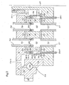
- An indexing arrangement 10 includes a rotor 12 spaced from a stator 14.
- a rotary seal 16 is located between the rotor 12 and the stator 14.
- a pressure chamber 18 is located between the rotor 12 and the rotary seal 16. Air under pressure is introduced into the pressure chamber 18 via an inlet (not shown).
- the rotor 12, stator 14 and rotary seal 16 have ports 20, 22 and 24 respectively.
- Conduits 26 extend through the ports 20 and extend into the ports 22. Seals in the form of O-rings 28 provide seals between the conduits 26 and the rotary seal 16.
- Conduits 27 extend into the ports 24 of the stator 14.
- the rotor 12 is made of mild steel and is lined with a liner 30.
- the liner 30 is made of a material known as Hastelloy.
- the stator 14 is made of mild steel and lined with highly polished liner 32 made of Hastelloy.
- the rotary seal 16 is made of polytetrafluoroethylene. It will however be appreciated that the materials from which the various components are made will depend on the nature of the fluid which flows through the indexing arrangement 10.
- a slew ring bearing 34 is interposed between the rotor 12 and the stator 14.
- the slew ring bearing 34 includes an inner race 36, ball bearings 38 and an outer race 40.
- a ring gear 42 is fixed to the outer race 40.
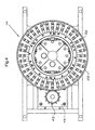
- the ring gear 42 is driven by a pinion gear 43 to rotate the rotor 12 and the rotary seal 16.
- the pinion gear 43 is driven by a motor 45 via a gearbox 45.1 ( Fig 5 ).
- An inner flushing chamber 44.1 is provided between an inner circumference 46 of the rotary seal 16 and an inner flushing chamber ring 48.1.
- a flushing fluid inlet 50.1 extends between the inner flushing chamber ring 48.1 and an O-ring receiving pressure chamber inner ring 52.1.
- the rotor 12 has a flushing air inlet 54.1.
- the stator 14 has a flushing air and leaked liquid outlet 56.1.
- An outer flushing chamber 44.2 is provided between an outer circumference 58 of the rotary seal 16 and an outer flushing chamber ring 48.2.
- a flushing fluid inlet chamber 50.2 extends between the outer flushing chamber ring 48.2 and an CD-ring receiving pressure chamber outer ring 52.2.
- the rotor 12 has a flushing air inlet 54.2.
- the stator 14 has a flushing air and leaked liquid outlet 56.2.
- the rotor 12 is secured to a rotor connector 58.
- the rotor connector 58 is in turn secured to a rotor of a distribution member (not shown).
- the stator 14 is fixed to a stator connector 60.
- the stator connector 60 is in turn secured to a stator of the distribution member.
- the rotor 12 is indexed or rotated by the pinion gear 43 about an axis of rotation 47 sequentially to align sets of ports 20 in the rotor 12 with sets of ports 24 in the stator 14.
- Pressurised air in the pressure chamber 18 forces the rotary seal 16 downwardly into sealing contact with the liner 32 of the stator 14.
- the rotary seal 16 can flex slightly to accommodate wear of the liner 32. The applicant believes that a floating seal with a one metre diameter will flex or deflect about one millimetre.
- the pressure of the air in the pressure chamber is between 600 to 1000 kPa, (6 to 10 bar) or 200 kPa (2 bar) above the highest fluid pressure.
Landscapes
- Engineering & Computer Science (AREA)
- General Engineering & Computer Science (AREA)
- Mechanical Engineering (AREA)
- Sealing Devices (AREA)
- Measuring Or Testing Involving Enzymes Or Micro-Organisms (AREA)
- Dicing (AREA)
- Polishing Bodies And Polishing Tools (AREA)
- Details And Applications Of Rotary Liquid Pumps (AREA)
- Sealing Using Fluids, Sealing Without Contact, And Removal Of Oil (AREA)
- Machine Tool Positioning Apparatuses (AREA)
- Machine Tool Units (AREA)
- Turbine Rotor Nozzle Sealing (AREA)
Claims (13)
- Dispositif d'indexation comprenant :un rotor (12) ;un stator (14) espacé du rotor ; etdes orifices dans le rotor, dans le stator et dans un joint d'étanchéité rotatif (16),caractérisé en ce que le joint d'étanchéité rotatif (16), qui peut tourner avec le rotor, est situé entre le rotor et le stator, en ce qu'une chambre, de pression (18) est située entre le rotor et le joint d'étanchéité rotatif afin de pousser le joint d'étanchéité rotatif en contact avec le stator et en ce que des moyens de raccordement (26) sont prévus pour relier des orifices respectifs (20) dans le rotor à des orifices respectifs (22) dans le joint d'étanchéité rotatif de telle sorte que, lors de l'utilisation, du fluide peut s'écouler à travers les orifices dans le rotor, dans les orifices dans le joint d'étanchéité rotatif en passant par les moyens de raccordement, et vers l'extérieur à travers les orifices dans le stator.
- Dispositif selon la revendication 1 dans lequel les moyens de raccordement (26) sont des conduits situés dans les orifices (20) du rotor (12) et s'étendant dans les orifices (22) du joint d'étanchéité rotatif (16).
- Dispositif selon la revendication 2 comprenant des joints d'étanchéité de conduit (28) destinés à procurer des joints d'étanchéité entre les conduits (26) et le joint d'étanchéité rotatif (16).
- Dispositif selon la revendication 3 dans lequel les joints d'étanchéité de conduit (28) sont situés dans des rainures s'étendant de manière circonférentielle dans les conduits (26).
- Dispositif selon l'une quelconque des revendications précédentes dans lequel le joint d'étanchéité rotatif (16) est annulaire.
- Dispositif selon la revendication 5 dans lequel la chambre de pression (18) a un joint d'étanchéité de chambre de pression extérieure (28) sur la circonférence extérieure (58) du joint d'étanchéité rotatif (15), et un joint d'étanchéité de chambre de pression intérieure (28) sur la circonférence intérieure (46) du joint d'étanchéité rotatif (16).
- Dispositif selon la revendication 6 dans lequel le joint d'étanchéité de chambre de pression extérieure (28) est situé dans un anneau de chambre de pression extérieure (52.2) relié au rotor (12), et dans lequel le joint d'étanchéité de chambre de pression intérieure (28) est situé dans un anneau de chambre de pression intérieure (52.1) relié au rotor (12).
- Dispositif selon l'une quelconque des revendications précédentes comprenant un dispositif d'évacuation destiné à évacuer un fluide quelconque, qui fuit entre le joint d'étanchéité rotatif et le stator, hors du dispositif d'indexation.
- Dispositif selon la revendication 8 dans lequel le dispositif d'évacuation comprend une chambre d'évacuation intérieure (44.1) adjacente à la circonférence intérieure (46) du joint d'étanchéité rotatif (16), et une chambre d'évacuation extérieure (44.2) adjacente à une circonférence extérieure (58) du joint d'étanchéité, avec les chambres d'évacuation intérieure et extérieure qui ont chacune une entrée (50.1, 50.2) à travers laquelle du fluide d'évacuation peut être introduit, et qui ont chacune une sortie de fluide d'évacuation (56.1, 56.2) à travers laquelle le fluide d'évacuation et du fluide qui a fui peuvent être évacués.
- Dispositif selon la revendication 9 dans lequel la chambre d'évacuation intérieure (44.1) est située entre la circonférence intérieure (46) du joint d'étanchéité rotatif (16) et un anneau de chambre d'évacuation intérieure (48.1), et dans lequel la chambre d'évacuation extérieure (44.2) est située entre la circonférence extérieure (58) du joint d'étanchéité rotatif et un anneau de chambre d'évacuation extérieure (48.2).
- Dispositif selon la revendication 10, lorsqu'elle est rattachée à la revendication 7, dans lequel la chambre d'évacuation intérieure (44.1) a une entrée de fluide d'évacuation (50.1) située entre l'anneau de chambre d'évacuation intérieure (48.1) et l'anneau de chambre de pression intérieure (52.1) ; et dans lequel la chambre d'évacuation extérieure (44 2) a une entrée de fluide d'évacuation (50.2) située entre l'anneau de chambre d'évacuation extérieure (48.2) et l'anneau de chambre de pression extérieure (52.2), les chambres d'évacuation extérieure et intérieure ayant des sorties de fluide d'évacuation (56.2, 56.1) dans le stator (14).
- Dispositif selon l'une quelconque des revendications précédentes dans lequel le rotor (12) comprend une couronne dentée (42) située sur la périphérie extérieur du rotor de telle sorte que, lors de l'utilisation, la couronne dentée peut être entraînée en rotation par un pignon d'entraînement (43) afin de faire tourner le rotor et le joint d'étanchéité rotatif (16).
- Dispositif selon la revendication 12 comprenant un roulement (34) interposé entre le rotor (12) et le stator (14).
Applications Claiming Priority (2)
| Application Number | Priority Date | Filing Date | Title |
|---|---|---|---|
| ZA200507481 | 2005-09-16 | ||
| PCT/IB2006/002547 WO2007031857A1 (fr) | 2005-09-16 | 2006-09-15 | Dispositif de mise au point |
Publications (2)
| Publication Number | Publication Date |
|---|---|
| EP1924794A1 EP1924794A1 (fr) | 2008-05-28 |
| EP1924794B1 true EP1924794B1 (fr) | 2011-04-13 |
Family
ID=37638565
Family Applications (1)
| Application Number | Title | Priority Date | Filing Date |
|---|---|---|---|
| EP20060808848 Not-in-force EP1924794B1 (fr) | 2005-09-16 | 2006-09-15 | Dispositif de mise au point |
Country Status (12)
| Country | Link |
|---|---|
| US (1) | US8544501B2 (fr) |
| EP (1) | EP1924794B1 (fr) |
| JP (1) | JP5198270B2 (fr) |
| CN (1) | CN101263326B (fr) |
| AT (1) | ATE505682T1 (fr) |
| AU (1) | AU2006290415B2 (fr) |
| BR (1) | BRPI0617020A2 (fr) |
| CA (1) | CA2622669C (fr) |
| DE (1) | DE602006021320D1 (fr) |
| IL (1) | IL189941A (fr) |
| WO (1) | WO2007031857A1 (fr) |
| ZA (1) | ZA200802807B (fr) |
Families Citing this family (3)
| Publication number | Priority date | Publication date | Assignee | Title |
|---|---|---|---|---|
| CN103620282B (zh) * | 2011-06-27 | 2015-03-11 | 托亚特胡立特公司 | 旋转分配装置 |
| JP6729500B2 (ja) * | 2017-06-14 | 2020-07-22 | 株式会社デンソー | バルブ装置 |
| CN109399749B (zh) * | 2018-10-10 | 2023-12-12 | 无锡万川环境装备技术有限公司 | 一种浅层气浮中心旋转密封装置 |
Family Cites Families (29)
| Publication number | Priority date | Publication date | Assignee | Title |
|---|---|---|---|---|
| US2209991A (en) | 1938-01-10 | 1940-08-06 | Chester T Mcgill | Multiport valve |
| US2996083A (en) * | 1958-07-10 | 1961-08-15 | Huska Paul | Continuous flow rotary selector valve |
| BE620972A (fr) * | 1961-08-07 | 1900-01-01 | ||
| US4253494A (en) * | 1978-01-17 | 1981-03-03 | Coal Industry (Patents) Limited | Constant speed uni-directional rotary sequence valve |
| US4223700A (en) * | 1979-01-02 | 1980-09-23 | Cameron Iron Works, Inc. | Flow line switch |
| DE2902364C2 (de) * | 1979-01-22 | 1983-03-24 | Klein, Schanzlin & Becker Ag, 6710 Frankenthal | Rohrweiche |
| US4467701A (en) * | 1979-01-26 | 1984-08-28 | Sigmon Company | Expansible device |
| US4271020A (en) * | 1979-10-22 | 1981-06-02 | Ryder International Corporation | Valve for filter device |
| US4633904A (en) * | 1984-12-10 | 1987-01-06 | Uop Inc. | Prevention of water hammer in rotary valve for interconnecting conduits |
| US4625763A (en) * | 1985-07-10 | 1986-12-02 | Uop Inc. | Disc-axial multiport valve |
| GB2209581B (en) | 1987-09-09 | 1991-05-22 | Armitage Shanks Ltd | Fluid control valve |
| US4951702A (en) * | 1989-08-28 | 1990-08-28 | Canceramic Limited | Bidet valve |
| US5188151A (en) * | 1991-10-22 | 1993-02-23 | Cold Jet, Inc. | Flow diverter valve |
| US5282652A (en) * | 1991-10-22 | 1994-02-01 | Werner Pipe Service, Inc. | Lined pipe joint and seal |
| US5704396A (en) * | 1996-01-05 | 1998-01-06 | Westinghouse Air Brake Company | Modulation rotary valve |
| US5806552A (en) * | 1997-03-21 | 1998-09-15 | Sterling Plumbing Group, Inc. | Fluid valve |
| US6146119A (en) * | 1997-11-18 | 2000-11-14 | Carrier Corporation | Pressure actuated seal |
| US5979483A (en) * | 1998-06-24 | 1999-11-09 | Occidental Chemical Corporation | Valve assembly and method |
| WO2004029490A1 (fr) | 2002-09-27 | 2004-04-08 | The Tongaat-Hulett Group Limited | Appareil de distribution rotatif |
| US6889710B2 (en) * | 2002-11-15 | 2005-05-10 | Air Products And Chemicals, Inc. | Rotary sequencing valve with flexible port plate |
| CN1453490A (zh) * | 2003-05-20 | 2003-11-05 | 南京华磁科技实业有限公司 | 平面旋转多流道阀门 |
| JP4405764B2 (ja) * | 2003-07-30 | 2010-01-27 | 株式会社北川鉄工所 | 回転継手の組み込まれた割出しテーブル |
| WO2005038312A2 (fr) * | 2003-10-17 | 2005-04-28 | Access Business Group International Llc | Ensemble vanne de derivation |
| US7343933B2 (en) * | 2004-04-27 | 2008-03-18 | Cameron International Corporation | Multi-port flow selector manifold valve and manifold system |
| CN101031745B (zh) * | 2004-08-26 | 2010-05-26 | 伊格尔工业股份有限公司 | 机械密封装置 |
| US7544293B2 (en) * | 2005-09-26 | 2009-06-09 | Semba Inc. | Valve and process for interrupted continuous flow chromatography |
| US20070235091A1 (en) * | 2006-04-06 | 2007-10-11 | Yoav Granot | Water tap assembly having a pull-out water-discharge head |
| US8020787B2 (en) * | 2006-11-29 | 2011-09-20 | Water Pik, Inc. | Showerhead system |
| US8191578B2 (en) * | 2007-11-13 | 2012-06-05 | Mego Afek Ac Ltd. | Rotary disc valve |
-
2006
- 2006-09-15 US US11/992,035 patent/US8544501B2/en not_active Expired - Fee Related
- 2006-09-15 BR BRPI0617020-0A patent/BRPI0617020A2/pt not_active Application Discontinuation
- 2006-09-15 CN CN2006800338204A patent/CN101263326B/zh not_active Expired - Fee Related
- 2006-09-15 ZA ZA200802807A patent/ZA200802807B/xx unknown
- 2006-09-15 JP JP2008530649A patent/JP5198270B2/ja not_active Expired - Fee Related
- 2006-09-15 AT AT06808848T patent/ATE505682T1/de not_active IP Right Cessation
- 2006-09-15 WO PCT/IB2006/002547 patent/WO2007031857A1/fr not_active Ceased
- 2006-09-15 CA CA 2622669 patent/CA2622669C/fr not_active Expired - Fee Related
- 2006-09-15 AU AU2006290415A patent/AU2006290415B2/en not_active Ceased
- 2006-09-15 EP EP20060808848 patent/EP1924794B1/fr not_active Not-in-force
- 2006-09-15 DE DE200660021320 patent/DE602006021320D1/de active Active
-
2008
- 2008-03-04 IL IL189941A patent/IL189941A/en not_active IP Right Cessation
Also Published As
| Publication number | Publication date |
|---|---|
| BRPI0617020A2 (pt) | 2011-07-12 |
| JP5198270B2 (ja) | 2013-05-15 |
| CA2622669C (fr) | 2011-11-15 |
| WO2007031857A1 (fr) | 2007-03-22 |
| AU2006290415A1 (en) | 2007-03-22 |
| ZA200802807B (en) | 2009-07-29 |
| US8544501B2 (en) | 2013-10-01 |
| IL189941A0 (en) | 2008-08-07 |
| IL189941A (en) | 2012-03-29 |
| CN101263326A (zh) | 2008-09-10 |
| CA2622669A1 (fr) | 2007-03-22 |
| EP1924794A1 (fr) | 2008-05-28 |
| JP2009508696A (ja) | 2009-03-05 |
| US20100206412A1 (en) | 2010-08-19 |
| CN101263326B (zh) | 2011-06-29 |
| AU2006290415B2 (en) | 2011-09-01 |
| ATE505682T1 (de) | 2011-04-15 |
| DE602006021320D1 (de) | 2011-05-26 |
Similar Documents
| Publication | Publication Date | Title |
|---|---|---|
| RU2570853C1 (ru) | Шпиндельный узел для системы накачивания шины | |
| EP4299964B1 (fr) | Raccord rotatif à passages multiples | |
| CN100356097C (zh) | 导液多通旋转阀 | |
| US7823929B2 (en) | Radial rotary transmission leadthrough | |
| KR940007405A (ko) | 시일 배열 나선홈 시일 시스템 및 가공 유체의 누출에 대해 시일링하는 방법 | |
| IL189941A (en) | Voting array | |
| EP0013455B1 (fr) | Raccord orientable pour un ou plusieurs conduits | |
| EP2705285B1 (fr) | Appareil de distribution rotatif | |
| EP0013454B1 (fr) | Raccord orientable pour un ou plusieurs conduits | |
| CN107398177B (zh) | 外转子式压力交换器 | |
| EP1552195B1 (fr) | Soupape destinee a modifier le sens d'ecoulement d'un fluide dans des conduits | |
| KR100305260B1 (ko) | 선미관베어링시스템 | |
| US20150198156A1 (en) | Control ring for a hydrostatical device | |
| US6227712B1 (en) | Internal oil flow path for gear box bearings | |
| WO2007031859A1 (fr) | Element de distribution | |
| NO166053B (no) | Roterbar roerkopling for et antall innkommende og utgaaenderoer. | |
| JP2801722B2 (ja) | ポンプ装置 | |
| RU205516U1 (ru) | Многоканальный гидропереход | |
| US12203575B2 (en) | Rotary union having pressure sleeve | |
| US20190136856A1 (en) | Hydraulic motor disc valve optimization | |
| JP6341669B2 (ja) | ポンプ | |
| RU2510612C1 (ru) | Конструктивно-технологический модельный ряд химических горизонтальных насосов и способ перекачивания химических жидкостных сред насосами конструктивно-технологического модельного ряда (варианты) | |
| HK40032137A (en) | Multiple passage rotary union | |
| JPH0718518B2 (ja) | 流路用スイベル継手装置 | |
| SE532439C2 (sv) | Hydraulisk motor |
Legal Events
| Date | Code | Title | Description |
|---|---|---|---|
| PUAI | Public reference made under article 153(3) epc to a published international application that has entered the european phase |
Free format text: ORIGINAL CODE: 0009012 |
|
| 17P | Request for examination filed |
Effective date: 20080311 |
|
| AK | Designated contracting states |
Kind code of ref document: A1 Designated state(s): AT BE BG CH CY CZ DE DK EE ES FI FR GB GR HU IE IS IT LI LT LU LV MC NL PL PT RO SE SI SK TR |
|
| 17Q | First examination report despatched |
Effective date: 20090625 |
|
| GRAP | Despatch of communication of intention to grant a patent |
Free format text: ORIGINAL CODE: EPIDOSNIGR1 |
|
| GRAS | Grant fee paid |
Free format text: ORIGINAL CODE: EPIDOSNIGR3 |
|
| GRAA | (expected) grant |
Free format text: ORIGINAL CODE: 0009210 |
|
| AK | Designated contracting states |
Kind code of ref document: B1 Designated state(s): AT BE BG CH CY CZ DE DK EE ES FI FR GB GR HU IE IS IT LI LT LU LV MC NL PL PT RO SE SI SK TR |
|
| REG | Reference to a national code |
Ref country code: GB Ref legal event code: FG4D |
|
| REG | Reference to a national code |
Ref country code: CH Ref legal event code: EP |
|
| REG | Reference to a national code |
Ref country code: IE Ref legal event code: FG4D |
|
| REF | Corresponds to: |
Ref document number: 602006021320 Country of ref document: DE Date of ref document: 20110526 Kind code of ref document: P |
|
| REG | Reference to a national code |
Ref country code: DE Ref legal event code: R096 Ref document number: 602006021320 Country of ref document: DE Effective date: 20110526 |
|
| REG | Reference to a national code |
Ref country code: SE Ref legal event code: TRGR |
|
| REG | Reference to a national code |
Ref country code: NL Ref legal event code: T3 |
|
| LTIE | Lt: invalidation of european patent or patent extension |
Effective date: 20110413 |
|
| PG25 | Lapsed in a contracting state [announced via postgrant information from national office to epo] |
Ref country code: LT Free format text: LAPSE BECAUSE OF FAILURE TO SUBMIT A TRANSLATION OF THE DESCRIPTION OR TO PAY THE FEE WITHIN THE PRESCRIBED TIME-LIMIT Effective date: 20110413 Ref country code: PT Free format text: LAPSE BECAUSE OF FAILURE TO SUBMIT A TRANSLATION OF THE DESCRIPTION OR TO PAY THE FEE WITHIN THE PRESCRIBED TIME-LIMIT Effective date: 20110816 |
|
| PG25 | Lapsed in a contracting state [announced via postgrant information from national office to epo] |
Ref country code: IS Free format text: LAPSE BECAUSE OF FAILURE TO SUBMIT A TRANSLATION OF THE DESCRIPTION OR TO PAY THE FEE WITHIN THE PRESCRIBED TIME-LIMIT Effective date: 20110813 Ref country code: LV Free format text: LAPSE BECAUSE OF FAILURE TO SUBMIT A TRANSLATION OF THE DESCRIPTION OR TO PAY THE FEE WITHIN THE PRESCRIBED TIME-LIMIT Effective date: 20110413 Ref country code: GR Free format text: LAPSE BECAUSE OF FAILURE TO SUBMIT A TRANSLATION OF THE DESCRIPTION OR TO PAY THE FEE WITHIN THE PRESCRIBED TIME-LIMIT Effective date: 20110714 Ref country code: AT Free format text: LAPSE BECAUSE OF FAILURE TO SUBMIT A TRANSLATION OF THE DESCRIPTION OR TO PAY THE FEE WITHIN THE PRESCRIBED TIME-LIMIT Effective date: 20110413 Ref country code: CY Free format text: LAPSE BECAUSE OF FAILURE TO SUBMIT A TRANSLATION OF THE DESCRIPTION OR TO PAY THE FEE WITHIN THE PRESCRIBED TIME-LIMIT Effective date: 20110413 Ref country code: ES Free format text: LAPSE BECAUSE OF FAILURE TO SUBMIT A TRANSLATION OF THE DESCRIPTION OR TO PAY THE FEE WITHIN THE PRESCRIBED TIME-LIMIT Effective date: 20110724 Ref country code: SI Free format text: LAPSE BECAUSE OF FAILURE TO SUBMIT A TRANSLATION OF THE DESCRIPTION OR TO PAY THE FEE WITHIN THE PRESCRIBED TIME-LIMIT Effective date: 20110413 |
|
| PG25 | Lapsed in a contracting state [announced via postgrant information from national office to epo] |
Ref country code: CZ Free format text: LAPSE BECAUSE OF FAILURE TO SUBMIT A TRANSLATION OF THE DESCRIPTION OR TO PAY THE FEE WITHIN THE PRESCRIBED TIME-LIMIT Effective date: 20110413 Ref country code: EE Free format text: LAPSE BECAUSE OF FAILURE TO SUBMIT A TRANSLATION OF THE DESCRIPTION OR TO PAY THE FEE WITHIN THE PRESCRIBED TIME-LIMIT Effective date: 20110413 |
|
| PLBE | No opposition filed within time limit |
Free format text: ORIGINAL CODE: 0009261 |
|
| STAA | Information on the status of an ep patent application or granted ep patent |
Free format text: STATUS: NO OPPOSITION FILED WITHIN TIME LIMIT |
|
| PG25 | Lapsed in a contracting state [announced via postgrant information from national office to epo] |
Ref country code: SK Free format text: LAPSE BECAUSE OF FAILURE TO SUBMIT A TRANSLATION OF THE DESCRIPTION OR TO PAY THE FEE WITHIN THE PRESCRIBED TIME-LIMIT Effective date: 20110413 Ref country code: RO Free format text: LAPSE BECAUSE OF FAILURE TO SUBMIT A TRANSLATION OF THE DESCRIPTION OR TO PAY THE FEE WITHIN THE PRESCRIBED TIME-LIMIT Effective date: 20110413 Ref country code: DK Free format text: LAPSE BECAUSE OF FAILURE TO SUBMIT A TRANSLATION OF THE DESCRIPTION OR TO PAY THE FEE WITHIN THE PRESCRIBED TIME-LIMIT Effective date: 20110413 Ref country code: PL Free format text: LAPSE BECAUSE OF FAILURE TO SUBMIT A TRANSLATION OF THE DESCRIPTION OR TO PAY THE FEE WITHIN THE PRESCRIBED TIME-LIMIT Effective date: 20110413 |
|
| 26N | No opposition filed |
Effective date: 20120116 |
|
| PG25 | Lapsed in a contracting state [announced via postgrant information from national office to epo] |
Ref country code: MC Free format text: LAPSE BECAUSE OF NON-PAYMENT OF DUE FEES Effective date: 20110930 |
|
| REG | Reference to a national code |
Ref country code: CH Ref legal event code: PL |
|
| REG | Reference to a national code |
Ref country code: DE Ref legal event code: R097 Ref document number: 602006021320 Country of ref document: DE Effective date: 20120116 |
|
| PG25 | Lapsed in a contracting state [announced via postgrant information from national office to epo] |
Ref country code: IT Free format text: LAPSE BECAUSE OF FAILURE TO SUBMIT A TRANSLATION OF THE DESCRIPTION OR TO PAY THE FEE WITHIN THE PRESCRIBED TIME-LIMIT Effective date: 20110413 |
|
| REG | Reference to a national code |
Ref country code: IE Ref legal event code: MM4A |
|
| PG25 | Lapsed in a contracting state [announced via postgrant information from national office to epo] |
Ref country code: LI Free format text: LAPSE BECAUSE OF NON-PAYMENT OF DUE FEES Effective date: 20110930 Ref country code: IE Free format text: LAPSE BECAUSE OF NON-PAYMENT OF DUE FEES Effective date: 20110915 Ref country code: CH Free format text: LAPSE BECAUSE OF NON-PAYMENT OF DUE FEES Effective date: 20110930 |
|
| PG25 | Lapsed in a contracting state [announced via postgrant information from national office to epo] |
Ref country code: LU Free format text: LAPSE BECAUSE OF NON-PAYMENT OF DUE FEES Effective date: 20110915 |
|
| PG25 | Lapsed in a contracting state [announced via postgrant information from national office to epo] |
Ref country code: BG Free format text: LAPSE BECAUSE OF FAILURE TO SUBMIT A TRANSLATION OF THE DESCRIPTION OR TO PAY THE FEE WITHIN THE PRESCRIBED TIME-LIMIT Effective date: 20110713 |
|
| PG25 | Lapsed in a contracting state [announced via postgrant information from national office to epo] |
Ref country code: TR Free format text: LAPSE BECAUSE OF FAILURE TO SUBMIT A TRANSLATION OF THE DESCRIPTION OR TO PAY THE FEE WITHIN THE PRESCRIBED TIME-LIMIT Effective date: 20110413 |
|
| PG25 | Lapsed in a contracting state [announced via postgrant information from national office to epo] |
Ref country code: HU Free format text: LAPSE BECAUSE OF FAILURE TO SUBMIT A TRANSLATION OF THE DESCRIPTION OR TO PAY THE FEE WITHIN THE PRESCRIBED TIME-LIMIT Effective date: 20110413 |
|
| PGFP | Annual fee paid to national office [announced via postgrant information from national office to epo] |
Ref country code: FI Payment date: 20150909 Year of fee payment: 10 Ref country code: DE Payment date: 20150908 Year of fee payment: 10 |
|
| PGFP | Annual fee paid to national office [announced via postgrant information from national office to epo] |
Ref country code: NL Payment date: 20150909 Year of fee payment: 10 |
|
| REG | Reference to a national code |
Ref country code: FR Ref legal event code: PLFP Year of fee payment: 11 |
|
| REG | Reference to a national code |
Ref country code: DE Ref legal event code: R119 Ref document number: 602006021320 Country of ref document: DE |
|
| PG25 | Lapsed in a contracting state [announced via postgrant information from national office to epo] |
Ref country code: FI Free format text: LAPSE BECAUSE OF NON-PAYMENT OF DUE FEES Effective date: 20160915 |
|
| REG | Reference to a national code |
Ref country code: NL Ref legal event code: MM Effective date: 20161001 |
|
| PG25 | Lapsed in a contracting state [announced via postgrant information from national office to epo] |
Ref country code: NL Free format text: LAPSE BECAUSE OF NON-PAYMENT OF DUE FEES Effective date: 20161001 |
|
| PG25 | Lapsed in a contracting state [announced via postgrant information from national office to epo] |
Ref country code: DE Free format text: LAPSE BECAUSE OF NON-PAYMENT OF DUE FEES Effective date: 20170401 |
|
| REG | Reference to a national code |
Ref country code: FR Ref legal event code: PLFP Year of fee payment: 12 |
|
| REG | Reference to a national code |
Ref country code: FR Ref legal event code: PLFP Year of fee payment: 13 |
|
| PGFP | Annual fee paid to national office [announced via postgrant information from national office to epo] |
Ref country code: FR Payment date: 20180813 Year of fee payment: 13 |
|
| PGFP | Annual fee paid to national office [announced via postgrant information from national office to epo] |
Ref country code: SE Payment date: 20180910 Year of fee payment: 13 Ref country code: GB Payment date: 20180912 Year of fee payment: 13 Ref country code: BE Payment date: 20180814 Year of fee payment: 13 |
|
| PG25 | Lapsed in a contracting state [announced via postgrant information from national office to epo] |
Ref country code: SE Free format text: LAPSE BECAUSE OF NON-PAYMENT OF DUE FEES Effective date: 20190916 |
|
| REG | Reference to a national code |
Ref country code: SE Ref legal event code: EUG |
|
| REG | Reference to a national code |
Ref country code: BE Ref legal event code: MM Effective date: 20190930 |
|
| PG25 | Lapsed in a contracting state [announced via postgrant information from national office to epo] |
Ref country code: BE Free format text: LAPSE BECAUSE OF NON-PAYMENT OF DUE FEES Effective date: 20190930 |
|
| GBPC | Gb: european patent ceased through non-payment of renewal fee |
Effective date: 20190915 |
|
| PG25 | Lapsed in a contracting state [announced via postgrant information from national office to epo] |
Ref country code: FR Free format text: LAPSE BECAUSE OF NON-PAYMENT OF DUE FEES Effective date: 20190930 Ref country code: GB Free format text: LAPSE BECAUSE OF NON-PAYMENT OF DUE FEES Effective date: 20190915 |