EP1925413A2 - Procédé et dispositif d'extrusion destinés à la fabrication de produits d'extrusion - Google Patents
Procédé et dispositif d'extrusion destinés à la fabrication de produits d'extrusion Download PDFInfo
- Publication number
- EP1925413A2 EP1925413A2 EP07022531A EP07022531A EP1925413A2 EP 1925413 A2 EP1925413 A2 EP 1925413A2 EP 07022531 A EP07022531 A EP 07022531A EP 07022531 A EP07022531 A EP 07022531A EP 1925413 A2 EP1925413 A2 EP 1925413A2
- Authority
- EP
- European Patent Office
- Prior art keywords
- strand
- steam
- extrusion
- plant according
- extrusion plant
- Prior art date
- Legal status (The legal status is an assumption and is not a legal conclusion. Google has not performed a legal analysis and makes no representation as to the accuracy of the status listed.)
- Granted
Links
Images




Classifications
-
- B—PERFORMING OPERATIONS; TRANSPORTING
- B27—WORKING OR PRESERVING WOOD OR SIMILAR MATERIAL; NAILING OR STAPLING MACHINES IN GENERAL
- B27N—MANUFACTURE BY DRY PROCESSES OF ARTICLES, WITH OR WITHOUT ORGANIC BINDING AGENTS, MADE FROM PARTICLES OR FIBRES CONSISTING OF WOOD OR OTHER LIGNOCELLULOSIC OR LIKE ORGANIC MATERIAL
- B27N3/00—Manufacture of substantially flat articles, e.g. boards, from particles or fibres
- B27N3/08—Moulding or pressing
- B27N3/28—Moulding or pressing characterised by using extrusion presses
-
- B—PERFORMING OPERATIONS; TRANSPORTING
- B27—WORKING OR PRESERVING WOOD OR SIMILAR MATERIAL; NAILING OR STAPLING MACHINES IN GENERAL
- B27N—MANUFACTURE BY DRY PROCESSES OF ARTICLES, WITH OR WITHOUT ORGANIC BINDING AGENTS, MADE FROM PARTICLES OR FIBRES CONSISTING OF WOOD OR OTHER LIGNOCELLULOSIC OR LIKE ORGANIC MATERIAL
- B27N3/00—Manufacture of substantially flat articles, e.g. boards, from particles or fibres
- B27N3/08—Moulding or pressing
- B27N3/18—Auxiliary operations, e.g. preheating, humidifying, cutting-off
-
- F—MECHANICAL ENGINEERING; LIGHTING; HEATING; WEAPONS; BLASTING
- F26—DRYING
- F26B—DRYING SOLID MATERIALS OR OBJECTS BY REMOVING LIQUID THEREFROM
- F26B1/00—Preliminary treatment of solid materials or objects to facilitate drying, e.g. mixing or backmixing the materials to be dried with predominantly dry solids
- F26B1/005—Preliminary treatment of solid materials or objects to facilitate drying, e.g. mixing or backmixing the materials to be dried with predominantly dry solids by means of disintegrating, e.g. crushing, shredding, milling the materials to be dried
-
- F—MECHANICAL ENGINEERING; LIGHTING; HEATING; WEAPONS; BLASTING
- F26—DRYING
- F26B—DRYING SOLID MATERIALS OR OBJECTS BY REMOVING LIQUID THEREFROM
- F26B17/00—Machines or apparatus for drying materials in loose, plastic, or fluidised form, e.g. granules, staple fibres, with progressive movement
- F26B17/02—Machines or apparatus for drying materials in loose, plastic, or fluidised form, e.g. granules, staple fibres, with progressive movement with movement performed by belts carrying the materials; with movement performed by belts propelling the materials over stationary surfaces
- F26B17/04—Machines or apparatus for drying materials in loose, plastic, or fluidised form, e.g. granules, staple fibres, with progressive movement with movement performed by belts carrying the materials; with movement performed by belts propelling the materials over stationary surfaces the belts being all horizontal or slightly inclined
Definitions
- the invention relates to a method and an extrusion press for producing extruded products with the features in the preamble of the method and device main claim.
- Conventional extrusion presses have extrusion presses that consist of an extruder, a downstream channel-like heating section and a subsequent cooling section and optionally a saw arranged at the end, which divides the strand by cross-sections into block-like individual pieces.
- Conventional heating systems have heated with oil or another medium and at least partly.
- the setting process takes a relatively long time, which brings a correspondingly large length of the heating passages and also the subsequent Auskühlumble with it.
- the energy consumption is high.
- a drying of the vegetable small parts in particular a targeted drying with the claimed degree of drying and / or with a wire or belt dryer has various advantages.
- the finished and set product, for example, the separated from the strand blocks are relatively insensitive to moisture and can have a significant residual moisture, eg up to 30% atro.
- Drying of small parts to a moisture content of approx. 6 - 18% at the outlet of the Drying is therefore economical and cost effective.
- the drying can also be extended to a lower degree of moisture, for example 2% atro or a higher degree of moisture up to about 20% atro or more, if required.
- the small parts can be transported during transport with dry air and with a limited temperature level of e.g. up to about 120 ° Celsius, are applied, resulting in a particularly uniform, fast and economical drying.
- the drying can take place in a continuous process, which is favorable in terms of production technology and, if necessary, ensures high output.
- the drying process can also be interrupted. Due to the mentioned degree of humidity, the small parts can be temporarily stored after drying in a silo or another container and further processed at a later time. The resumption of water and moisture and a product change are low here.
- the coarse crushing before drying and fine comminution can be done after drying and before extrusion.
- a small parts producer such as a sawmill
- small vegetable parts of a pre-crushing As a result, the surface is increased, which is favorable for the subsequent drying.
- subsequent comminution can follow, with which a particle size of the small parts suitable for extrusion can be set. At the same time this can be a Homogenization of small parts material can be achieved. Both are favorable for the subsequent gluing and the extrusion process.
- it is advantageous for energetic reasons to carry out this comminution and the adjustment of the particle size after drying Dried small parts are easier to crush and with less energy and machinery than the wet raw material. Alternatively, this comminution and adjustment can take place before drying.
- the steam treatment has the further advantage that it allows a faster and more uniform heating of the strand and a faster setting. It is particularly advantageous when working with saturated steam and its condensation in the strand. By changing the state of aggregation, a lot of heat energy can be released quickly and evenly in the strand. It is advantageous to tune the steam quantity and the vapor pressure to the heat absorption capacity of the applied strand area and to dimension such that on the one hand the strand can be completely penetrated in the transverse direction and can set and the amount of steam in the strand substantially completely can condense. As a result, excess steam and a complex and space-consuming steam disposal via reactors or the like. Avoid. In addition, the environmental impact is lower.
- the steam treatment of the strand is preferably carried out in such a way that the strand subsequently has a high dimensional stability. This means that it shows no or only insignificant deformations after removal of external pressure.
- the claimed technique it is possible to complete the setting process in the strand by the steam treatment so far that the glue strength is greater than the internal stresses in the strand.
- the heating section can be kept very short, which leads to a substantial reduction in the overall length of the extruder.
- the cooling section can connect directly to the outlet of the heating section and to the end of the steam supply or the steam treatment. Due to the optimal energy utilization, the cooling section can be kept shorter than in the prior art, which also brings a considerable reduction in the overall length of the extruder with it.
- the claimed evaporation technology also provides the necessary operational reliability in the extrusion of small plant parts with a relatively high degree of moisture. Thanks to the vapor deposition, the extrusion channel can have substantially rigid walls, without this leading to damage in the strand.
- the small parts moisture can be heated and shared via the steam and energy supply for the setting process.
- the shape stability of the strand achieved at the end of the vaporization makes its further treatment and in particular the passage through the cooling section unproblematic.
- a high moisture content of small parts can lead to cracks and delamination in the strand. Although this can be prevented by additional measures and is insofar practicable.
- the preferred vapor deposition technique offers further advantages.
- the steam quantity control also has the advantage that it provides for clear and reproducible process conditions and for a secure setting of the binder in the strand. On the other hand, excess steam is largely avoided, which leads to a significant reduction in construction and operating costs.
- Degassing generators and vapor recirculation are dispensable.
- the preferably saturated process steam is also optimally utilized. It condenses in a controllable strand area, whereby the heat required for setting is released in an optimal way and with uniform distribution via the phase or aggregate change. Also favorable is the fact that it is possible to work with relatively low quantities of steam and thus cost-effectively.
- the capacity of the vaporization system can also be designed smaller and cheaper.
- the vapor deposition is carried out in the outlet region of the recipient and / or in the subsequent section of the heating channel.
- the strand usually has the highest compression, so that the heat introduced by the steam can be optimally used for the setting. It is also favorable if fixed or rigid channel walls are present in the vaporization area and if strand formation takes place in the vaporization area.
- the setting process is significantly improved and accelerated by targeted evaporation, whereby the heating channel designed shorter and the overall length of the entire extruder can be significantly reduced. This leads to a higher economic efficiency.
- the steam may e.g. be fed continuously or intermittently with the strand stranded. In both cases, a steam quantity control is advantageous.
- the drive can be reversing and have a ram. This has the advantage that the press ram seals the strand end gas-tight and limits the steam expansion zone to the rear. Alternatively, continuous extrusion, e.g. with a snail, also possible.
- the mecanical feed region of the steam is limited in the strand and extends in particular over a strand feed length of one to two extrusion strokes.
- FIG. 1 shows in a schematic plan extruder (1) for producing a strand (2) from small plant parts, especially small pieces of wood such as sawdust, wood chips or the like., Which are mixed with a thermo-reactive binder or adhesive, for example.
- the small vegetable parts may alternatively or additionally consist of another plant material.
- she are from a small parts producer (51), for example, a sawing or planing mill, where they arise as a processing waste, fed to the extrusion press (1).
- the strand (2) can have any cross-sectional shape, e.g. may be circular, oval or prismatic, in particular substantially square or rectangular, with possibly rounded, chamfered or chamfered corner areas.
- the side walls of the strand (2) may be flat, curved or profiled.
- the strand (2) may be massive or in places, e.g. in the middle, be hollow.
- the ratio of width to height of the strand cross-section is e.g. in the range of about 1, in particular in the range between 0.7 to 2, as e.g. is common for pallet blocks.
- the strand (2) has thereby e.g. the rod shape shown in the drawings.
- the width to height ratio may be significantly greater, thereby giving the strand (2) a board or board shape.
- the extrusion press (1) consists of a drying device (3) for the small vegetable parts and an extruder (4), which can be connected to each other via a small parts feeder (6) in the form of one or more suitable conveyors or the like.
- one or more comminution devices (52, 53) for the small vegetable parts may be present.
- a pre-crushing (52) is arranged, in which, for example, supplied as coarse sawdust or wood chips vegetable small parts are brought to a size suitable for drying. For example, they are coarsely crushed to increase their free surface for subsequent drying.
- Behind the outlet of the drying device (3) can be post-shredding (53) be arranged, in which the dried vegetable small parts are brought to a maximum particle size, which is suitable for the subsequent extrusion process. In this case, a homogenization of the small parts material and a homogenization of the particle sizes can take place.
- the shredders (52, 53) are equipped with suitable machinery and tools and may also include measuring equipment for particle size measurement and shredding control and regulation. Alternatively, it is already possible to set the particle size suitable for extrusion in the pre-shredding (52) and to dispense with subsequent comminution (53).
- the extrusion press (1) may further comprise a gluing station (50) at a suitable location, e.g. in the conveying direction behind the secondary comminution (52) and in the area of the small parts feed (6).
- a gluing station 50
- the preferably previously dried vegetable small parts are provided with the binder, e.g. is sprayed on.
- intermediate storage in the form of a silo or other container in the region between the drying device (3) and the extrusion press (4).
- the extruder (4) has an extruder (5) with a downstream heating section (12) and a subsequent cooling section (13), which are arranged one behind the other in the pressing direction (9).
- a separating device (14) for the strand (2) may be arranged. This may be, for example, a saw, which divides the strand by the cross sections into a plurality of block-like individual pieces, eg pallet blocks.
- the extruder (4) may further comprise one or more conveyors or conveyor lines (15) behind the Auskühlumble and / or behind the separating device (14) are arranged.
- the drying device (3) is used for drying the vegetable small parts before further processing and extrusion.
- the small parts of your natural moisture content are dried down so far that they are e.g. at the end of the drying a residual moisture content or degree of moisture of about 6 to 20% atro, preferably from about 6 to 14% atro, have.
- the degree of moisture may also be lower, e.g. up to about 2% atro or higher up to about 20% atro or more.
- the drying device (3) can be of any suitable design for this purpose.
- the drying device (3) as a belt dryer (34) is formed.
- the lying on an air-permeable small parts carrier (36) small parts are dried by a heated dry air stream. This can be done stationary or during the transport of small vegetable parts.
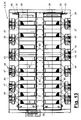
- the in FIGS. 11 to 13 shown belt dryer (34) has four drying lines, which are each equipped with at least one endless circulating small parts carrier (35), at least one circulating means (46) for the dry air flow and at least one heating device (44).
- the four drying lines are housed together in a common machine frame (35).
- the number of drying lines may vary.
- the belt dryer (4) may have only one line or any other number of lines.
- the small parts carrier (36) is designed as an air-permeable and perforated, elastic and tensile transport belt, for example, which is guided in an endless loop through the dry line and is set in circulation with a drive (38).
- the band (36) has a straight and substantially horizontally extending upper strand and an underlying lower strand and is guided over rollers (41) and deflected.
- the drive (38) is arranged on the output side and can be accompanied by a clamping device with at least one adjustable roller (41), which in FIG. 11 is indicated by the loop representation on the right side.
- the small vegetable parts are transported on the upper run and traversed during transport through the heated dry air flow transverse to the Banderstreckung and dried.
- a feed station (39) is arranged, which is provided with a metering device, e.g. a worm, can be equipped and with the small parts are applied to the upper strand.
- the bed is preferably uniform and covers the upper run of the band (36) in full area. Laterally, the upper strand is sealed and supported in a longitudinal tape guide (37).
- the band (36) has such a high inherent stability that the transverse sag is limited.
- a delivery point (40) is arranged, at which the dried vegetable small parts are released from the belt (36) and conveyed in a suitable manner.
- the circulation device (46) has several fans (47) or other suitable Luftumicalzators, each of which is connected to one or more chambers (48) and there generate the dry air flow.
- the eg externally arranged blower (47) generate in the chamber (48) a negative pressure below the upper run of the belt (36).
- an air supply (42) is arranged in the chambers (48). This may be an inlet opening for the ambient air, which is closed by a grid or possibly a filter.
- the fan (47) is connected in each case in the space between the upper and lower run of the belt (36) laterally to the chamber (48) with a suction shaft and is provided on the output side with an air duct (49) through which the exhaust air laden with moisture (43 ) is delivered, possibly to the environment.
- the heater (44) may be formed in different and possibly multi-stage manner.
- a plurality of heating coils (45) are arranged in the flow path of the supply air (42) before reaching the belt upper run, in which the supply air is heated.
- the heating and the formation of the heating register (45) may be formed in any desired manner.
- the supply air may e.g. be passed through a heat exchanger or heated by a firing.
- the heating register (45) can be arranged at a small distance above the upper run and the small parts bed.
- the supply air flows through the heating register (45) and is heated to the desired drying temperature.
- a multi-stage heater (44) e.g. preheating the supply air done by a heat exchanger, which is fed by a flue gas condensation from a cogeneration plant.
- the drying temperature may be in a range of up to 120 ° C, for example.
- the heated dry air flows through the small parts bed on the upper strand and thereby takes Moisture on.
- the chamber area above the belt upper run can be sealed in such a way that in the chambers (48) the supply air can only flow through the heating register (45).
- the heating registers may in this case have a smaller area size than the chamber base area.
- the drying device (3) may be formed as a stationary sieve dryer, in which the small vegetable parts are poured onto tray or pallet-like sieves and are flowed through in a drying oven by heated dry air.
- a drying oven by heated dry air.
- Several sieves can be housed in a rack or dolly.
- the guidance of the dry air flow may be different and need not be guided transversely to the main plane of the small parts carrier (36). There may also be inclined or parallel flow directions.
- the extruder (5) may be of any suitable type. In the embodiment shown, it is a ram extruder with a reversing driven pressing member (8), eg a ram.
- the basic form of such an extruder (5) is for example from the WO 99/48659 A1 or the WO 02/34489 A1 known.
- the extruder (5) consists of a with the small parts supply (6) connected filling station (11) for filling the small vegetable parts in a filling and pressing shaft.
- a recipient (16) adjoins the filling station (11) in the extrusion direction (9), into which the filling material is pushed by a pressing member (8) and thereby compacted.
- the recipient (16) is formed as a closed channel with rigid and stationary channel walls, which form the strand (2) in the outline and which may have a slight conical extension.
- the directly adjacent to the recipient (16) subsequent heating channel (17) may be a Vortexgang also rigid and stationary channel walls (18), which surround the strand (2) circumferentially tight.
- the recipient (16) may be part of the extruder (5). As an alternative and as in the embodiment shown, it can at least partially extend into the heating channel (17) or be arranged there. FIGS. 2 to 8 show such embodiments.
- the strand (2) is advanced in the embodiment shown intermittently or clocked and pressed.
- the pressing member (8) is designed as a reciprocating ram connected to a suitable reversing drive (7), e.g. can be designed as a hydraulic cylinder, as an electric crank mechanism or the like.
- the extruder (5) further comprises a vaporization device (21), which comprises a steam generator (22) with one or more steam lines (23) and a steam supply (24) for acting on the strand (2).
- the steam generator (22) produces, for example, a saturated or superheated steam of water or other suitable medium.
- the generated vapor pressures and temperatures depend on the small parts material, the strand dimensions, in particular the diameter, the applied strand volume and others Specifications and can vary accordingly. Conveniently in practice, for example in the saturated steam generation from water pressures of 5 bar and more, eg 10 bar or more and the associated steam temperatures.
- the steam is transported via the line (s) (23) to the steam supply (24) and placed there on or in the strand (2).
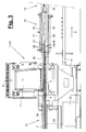
- the steam is supplied to the strand (2) in the manner explained below from the inside with an internal supply (26) through at least one channel-like opening.
- FIG. 3 shows this variant.
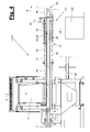
- the steam can be supplied from the outside with an external feed (25) to the strand casing according to the in FIGS. 4 to 8 shown variant.
- the vapor deposition takes place in these variants preferably in the region of maximum strand density, i. in the region of the recipient (16) and / or the area of the heating chamber (17) adjoining in the extrusion direction (9).
- the vaporization may e.g. be made only in one place and only in the aforementioned area.
- several vapor deposition sites may be present in the extrusion direction (9), with the vaporization parameters mentioned below being valid for the first vaporization site at the recipient (16) or at the channel region.
- the vaporization device (21) further comprises a valve for opening and closing the steam supply, which is connected to a controller and controlled by this.
- the amount of steam introduced is controlled, for example, via the opening time and / or the opening width of the valve.
- the controller may be coupled to the drive (7) of the ram (8) and control the valve in response to the drive movements.
- a hollow strand (2) is produced by means of a pressing mandrel (29) arranged centrally in the recipient (16) and possibly also in the heating channel (17).
- a plurality of mandrels distributed arbitrarily over the strand cross-section may be present.
- the press mandrel (29) is on the back by means of a fitting in the machine frame (10) of the extruder (5) releasably held.
- the ram (8) is provided on the inside with a recess and slides over the press mandrel (29).
- the press mandrel (29) has a constant over its length and, for example, circular cross-section with a cylindrical shell.
- the mandrel (29) may have a different cross-sectional shape, for example a prismatic cross-section. Accordingly, the internal cavity in the strand (2) is designed.
- the recipient (16) and the heating channel (17) may also have any cross-sectional shape, which may be circular, oval, prismatic or otherwise formed.
- the inside hollow mandrel (29) is a part of the vapor deposition device (21) and has on its jacket, preferably in the region of the free end, a peripheral steam outlet region (27) for steaming the tightly adjacent strand (2) ,
- the jacket here has a uniform contour over the mandrel length.
- the press mandrel (29) is closed, so that the steam preferably exits only radially on the jacket via local steam outlet openings (28) and passes directly into the adjoining strand (2).
- the steam exit region (27) has a limited length that is shorter than the mandrel length.
- the steam outlet area (27) is located, for example, at the end of the mandrel and in the entrance area of the heating channel (17). He may alternatively extend a little way back into the region of the recipient (16). Alternatively, the steam outlet region (27) can also be located in an outlet-side subregion of the recipient (16). These are the areas in the extruder (5) in which the strand (2) has the highest compression. In the area of the filling station (11), the mandrel jacket is closed and possibly thermally insulated.
- the steam outlet region (27) is at the same time the feed region, to which the strand (2) the steam is supplied.
- the vapor can spread somewhat in the axial direction and also penetrate into the strand regions adjoining the feed region (27).
- the feed area (27) is so far away from the filling station (11) that preferably no steam can penetrate into the filling space.
- the strand (2) can alternatively or additionally be vapor-deposited from the outside.
- suitable steam outlet openings (28) of any type, size and arrangement are available: It may be, for example, holes or slots in the channel wall, with Distribution channels in the Heinzkanalproblemn (18) and hereby connected to the steam line (23).
- the feed region (27) is limited in length and is located in the outlet region of the recipient (16) and / or in the subsequent area of the heating channel (17).
- design can be dispensed with a press mandrel (29), wherein a solid strand (2) is formed.
- the axial length of the steam outlet region (27) or of the steam supply region is limited.
- the length is e.g. equal to or less than the strand feed length of one to two extrusion strokes. This is the feed length of the strand (2) resulting from the stroke length of 1 to 2 pressing strokes of the pressing member (8).
- the length of the steam exit region (27) may be e.g. about 150 to 500 mm, preferably about 250 mm.
- vaporization of the strand (2) takes place only in the described range. Alternatively, further vaporization areas may be present.
- FIGS. 2 to 8 variants shown may be in the channel area at or before the steam supply (24) of the strand (2) in addition and eg from the outside to be heated.
- the channel walls (18) may for this purpose have heating elements or be heated by the steam from the inside.
- no heating or heating of the strand (2) takes place more.
- the steam supply (24) is preferably also at the corresponding end of the heating channel (17).
- the press mandrel for example, a support tube with the fitting at the rear end.
- a steam tube is arranged, which has the same outer contour as the support tube.
- the steam pipe has an internal steam chamber and a plurality of outlet openings (28) for the steam distributed around the circumference of the pipe.
- the outlet openings (28) are formed, for example, as radial through-holes in the jacket of the steam pipe. Such through holes are sufficient on their own. she may alternatively be connected to the outside with laterally leading away and, for example, crosswise arranged distribution channels.
- the distribution channels may be formed, for example, as outside grooves in the jacket, which open at the said through hole.
- the steam pipe At the front, the steam pipe at the free front end by a lid or the like. Vapor-tight. At the other end, the steam pipe is flush and flush with the support tube. This may be a detachable connection, e.g. be a screw to remove the steam pipe for cleaning and maintenance purposes and to replace if necessary. Alternatively, a solid compound, e.g. a weld, be present. At this end, there is also disposed a seal for preventing the axial steam escape, e.g. is located at a neck nozzle of the steam pipe, which projects a piece into the support tube via a corresponding recess.
- a seal for preventing the axial steam escape e.g. is located at a neck nozzle of the steam pipe, which projects a piece into the support tube via a corresponding recess.
- the steam is supplied to the steam pipe via a reduced in diameter relative to the steam pipe internal steam line, which is connected via the said remote controllable valve with the steam generator (22).
- the steam line is designed, for example, as a rigid feed tube laid in the carrier tube, which is held and fastened here by radial guides.
- the feed tube protrudes through the seal into the steam chamber. If necessary, it can slide back and forth in the seal to compensate for thermal expansion.
- the feed pipe is open, so that the steam can escape here and be distributed in the steam chamber and can escape through the outlet openings (28) into the strand (2). Due to the thin feed tube, the vapor volume located behind the valve is relatively small.
- the steam supplied to the strand (2) can be controlled via the valve and its opening times with high accuracy.
- the press mandrel (29) as in the illustration of FIG. 3 be designed as a single-stranded steam tube with a single continuous internal cavity. Further, it is possible to supply the steam continuously and independently of the press cycle to the strand (2).
- the valve ensures an evenly constant steam supply and steam quantity control.
- a single-stranded mandrel (29) and a throttle valve are particularly suitable for permanent vapor deposition.
- the strand (2) is e.g. saturated steam in a controlled amount of steam via the steam outlet region (27) and fed to the feed.
- the amount of steam and the vapor pressure are matched to the heat absorption capacity of the applied strand area and e.g. so dimensioned that the supplied steam provides in this strand area for the required setting and thereby substantially completely condensed. Excess steam can be substantially avoided, so that the strand (2) on the outside no steam or little steam escapes.
- the amount of steam is at the lower limit so that it is sufficient for the penetration of the entire cross-section of the strand (2) and for the setting of the strand (2) or the binder contained therein in the entire applied strand area. Upwards, the amount of steam is so dimensioned that substantially all the saturated steam introduced into the strand (2) can condense there and that preferably no excess vapor exits the strand (2). It is the aim of avoiding any excess vapor. In practice, this does not always achieve the desired level. It lies within the framework of Invention, when said conditions and ratios are at least substantially achieved.
- the heat energy or enthalpy contained in the saturated steam is abruptly released in the impinged strand area and ensures uniform heating and extreme acceleration of the thermal setting reaction of the strand material.
- the process can be supported by a possibly existing external additional heating in the chamber walls.
- the hardening and setting process in the strand (2) can be effected solely by the condensation.
- the Schufflenin can thereby be significantly reduced and is e.g. about 1.5 m.
- the energy required to set the strand (2) is essentially introduced by the vapor.
- the setting process in the strand (2) is completed so far that the strand has reached its dimensional stability. This means that the strand (2) shows no or substantially no deformation when taking away an external pressure and an external guide.
- the volume of porous material is capable of accommodating the volume of vapor because upon contact with the colder chip material offering a very large contact surface of the chips, the condensation process begins immediately and the vapor volume collapses before the mixture leaves the squeeze channel section closed on all sides and the vapor pressure cracks could cause in the product strand.
- the condensate is homogeneously distributed in the material volume.
- the cured product is no different from products recognizable without steaming.
- the steam quantity control is in the embodiment of FIG. 3 provided with a mecanical dipfung (26) from the press mandrel (29) in the contact area with the strand (2), wherein the steam from the outlet openings (28) and possibly the distribution channels directly into the strand (2) penetrates.
- the steam quantity control can also be combined with an external vapor deposition (25) of the strand (2) in the region at the recipient (16) and / or subsequent region of the heating channel (17).
- the steam quantity control can also be used in conjunction with a combined internal and external vapor deposition (25, 26) of the strand (2).
- the steam supply (24) is located at the rear end of the heating channel (17) behind the recipient (16) in the pressing direction (9).
- the heating channel (17) in both variants rigid and fixedly arranged channel walls (18) surrounding the strand (2) circumferentially tight and form in its outer contour , where in the region of the channel may possibly have a slight conical or stepped extension.
- the heating channel (17) at least one limited movable channel wall (19), which is arranged for example at the top.
- the mobility may be in a pivotal movement, wherein the front end of the channel wall (19) is obtained in the manner of a hinge on the subsequent fixed wall portion and the rear end can pivot up and down.
- an adjusting device (20) is present, which has a suitable controllable drive, for example a hydraulic cylinder.
- the movable channel wall (19) and the adjusting device (20) may be omitted in favor of continuous solid channel walls (18).
- the movable channel wall (19) can be held and locked in the extrusion operation with such a force that it does not evade under normal operating conditions and evades only when an abnormal overpressure occurs in the hollow channel interior.
- the movable channel wall (19) can be used as a strand brake in order to produce the counter-pressure required to achieve the strand compaction with respect to the feed force of the pressing member (8).
- the movable channel wall (19) of the adjusting device (20) with controlled force and possibly a controlled path to the strand (2) is pressed and brakes it by frictional force. This braking effect is present only over a portion of the extrusion stroke until the required compression is achieved and the strand (2) can then be advanced along the entire length. In this period, the channel wall (19) is released and canceled the braking effect.
- FIG. 2 shows the subsequent to the heating section (12) Ausksselumble (13).
- This is also formed like a tube or channel and consists of at least one cooling channel (30) in FIGS. 9 and 10 is shown.
- modularly formed cooling channels (30) can according to FIG. 2 behind each other be arranged and form a Auskühlrange (13) with the desired length.
- the module or channel length can be for example about 3 m, so that, for example, by two or three modules, a distance of 6 m or 9 m can be achieved.
- the cooling channel (30) can be formed by rigid and stationary channel walls (31) and by movable channel walls (32) or wall sections, which are possibly spaced at the adjacent longitudinal edges to form free spaces.
- the movable channel walls (32) are connected to one or more adjusting devices (33) which can be controlled controlled for advancing and lifting the movable channel walls (32) from the strand (2).
- the parts are arranged and mounted together on a machine frame (10) possibly connected to the extrusion press (5).
- the actuators (33) have a suitable drive, e.g. Hydraulic cylinder, which are connected to the aforementioned control of the extruder (5).
- the adjusting devices (33) are actuated in the extrusion cycle.
- the movable channel walls (32) are turned on and clamp the strand (2). Once the desired compaction is achieved, open the movable channel walls (32) and release the strand feed. During the return stroke of the extrusion process (8), the strand (2) can be held again.
- the channel walls (31,32) can absorb the thermal energy contained in the strand (2) by heat conduction and release by convection to the environment. Furthermore, active cooling of the channel walls (31, 32) with water or other suitable media is possible. The distances or free spaces between the channel walls (31,32) allow evaporation of excess moisture from the strand (2).
- the extrusion press (1) includes the described drying device (3), the shredders (52, 53) and the extruder (4). These components each have independent inventive significance.
- the drying device (3) and in particular the belt dryer (34) shown can alternatively be used in conjunction with a differently configured extrusion press (4), which, for example, according to W02002 / 034489 A1 is trained.
- the extruder device (4) and in particular the extruder (5) with the described evaporation technique to achieve a dimensionally stable strand (2) after the evaporation can on the other hand be used in conjunction with another drying device (3) or without such a drying device (3).
- another drying device (3) for example, it is possible to process small vegetable parts with a natural moisture content incurred in woodworking, such as wood chips, wood shavings or the like. Such small parts are not dried again separately, but can be fed directly to the extrusion process after mixing with binder.
- the extrusion and steaming technique described can also be used with vegetable small parts, which have a lower moisture content.
- the pressing member (8) may for example be a worm and also provide for a continuous feed.
- the design of the vapor deposition device (21) and its components is also freely changeable.
- the targeted and localized steam escape at the press mandrel (29) can also be achieved with a different structural design.
Landscapes
- Engineering & Computer Science (AREA)
- Life Sciences & Earth Sciences (AREA)
- Manufacturing & Machinery (AREA)
- Wood Science & Technology (AREA)
- Forests & Forestry (AREA)
- Mechanical Engineering (AREA)
- General Engineering & Computer Science (AREA)
- Dry Formation Of Fiberboard And The Like (AREA)
- Drying Of Solid Materials (AREA)
- Fodder In General (AREA)
Priority Applications (2)
| Application Number | Priority Date | Filing Date | Title |
|---|---|---|---|
| EP11181750.8A EP2425947B1 (fr) | 2006-11-21 | 2007-11-21 | Dispositif d'extrusion |
| PL07022531T PL1925413T3 (pl) | 2006-11-21 | 2007-11-21 | Sposób i wytłaczarka do wytwarzania produktów wytłaczanych |
Applications Claiming Priority (1)
| Application Number | Priority Date | Filing Date | Title |
|---|---|---|---|
| DE200620017826 DE202006017826U1 (de) | 2006-11-21 | 2006-11-21 | Strangpressanlage zum Herstellen von Strangpressprodukten |
Related Child Applications (2)
| Application Number | Title | Priority Date | Filing Date |
|---|---|---|---|
| EP11181750.8A Division-Into EP2425947B1 (fr) | 2006-11-21 | 2007-11-21 | Dispositif d'extrusion |
| EP11181750.8A Division EP2425947B1 (fr) | 2006-11-21 | 2007-11-21 | Dispositif d'extrusion |
Publications (3)
| Publication Number | Publication Date |
|---|---|
| EP1925413A2 true EP1925413A2 (fr) | 2008-05-28 |
| EP1925413A3 EP1925413A3 (fr) | 2009-04-01 |
| EP1925413B1 EP1925413B1 (fr) | 2016-12-28 |
Family
ID=39232749
Family Applications (2)
| Application Number | Title | Priority Date | Filing Date |
|---|---|---|---|
| EP11181750.8A Active EP2425947B1 (fr) | 2006-11-21 | 2007-11-21 | Dispositif d'extrusion |
| EP07022531.3A Active EP1925413B1 (fr) | 2006-11-21 | 2007-11-21 | Procédé et dispositif d'extrusion destinés à la fabrication de produits d'extrusion |
Family Applications Before (1)
| Application Number | Title | Priority Date | Filing Date |
|---|---|---|---|
| EP11181750.8A Active EP2425947B1 (fr) | 2006-11-21 | 2007-11-21 | Dispositif d'extrusion |
Country Status (5)
| Country | Link |
|---|---|
| EP (2) | EP2425947B1 (fr) |
| DE (2) | DE202006017826U1 (fr) |
| ES (2) | ES2607079T3 (fr) |
| PL (2) | PL2425947T3 (fr) |
| PT (2) | PT2425947T (fr) |
Cited By (3)
| Publication number | Priority date | Publication date | Assignee | Title |
|---|---|---|---|---|
| DE202009012239U1 (de) | 2009-09-11 | 2011-01-20 | Anton Heggenstaller Gmbh | Produktionseinrichtung |
| DE202009012299U1 (de) | 2009-09-11 | 2011-02-03 | Anton Heggenstaller Gmbh | Trenneinrichtung |
| DE202015101653U1 (de) | 2015-04-02 | 2016-07-05 | Pfeifer Holz Gmbh | Trenneinrichtung |
Families Citing this family (3)
| Publication number | Priority date | Publication date | Assignee | Title |
|---|---|---|---|---|
| DE202008010304U1 (de) | 2008-08-01 | 2009-12-17 | Anton Heggenstaller Gmbh | Herstellungsanlage für Pressprodukte |
| DE202018105738U1 (de) * | 2018-10-08 | 2020-01-09 | Pfeifer Holz Gmbh | Anlage zum Herstellen von Klötzen |
| CN116968369B (zh) * | 2023-07-31 | 2025-09-09 | 石河子市洁曼卫生材料科技有限公司 | 一种高效棉花加湿压饼系统 |
Citations (6)
| Publication number | Priority date | Publication date | Assignee | Title |
|---|---|---|---|---|
| EP0573695A1 (fr) | 1992-06-10 | 1993-12-15 | Mikhail Vasilievich Birjukov | Procédé et dispositif pour le moulage des produits moulées |
| GB2282436A (en) | 1993-10-01 | 1995-04-05 | Trade & Industry Ltd | Apparatus for drying tea leaves |
| WO1999048659A1 (fr) | 1998-03-25 | 1999-09-30 | Karl Schedlbauer | Procede et dispositif permettant de fabriquer un materiau profile |
| DE29912822U1 (de) | 1999-07-22 | 2000-08-17 | Anton Heggenstaller AG, 86556 Kühbach | Strangpresse für pflanzliche Kleinteile |
| EP1595663A2 (fr) | 2004-05-14 | 2005-11-16 | Summit Views Llc | Procédé de fabrication des buches densifiées de bois indésirables et mort, et procédé commercial |
| EP1752267A2 (fr) | 2005-08-10 | 2007-02-14 | Anton Heggenstaller GmbH | Procédé pour la fabrication de produits extrudés et presse d'extrusion |
Family Cites Families (8)
| Publication number | Priority date | Publication date | Assignee | Title |
|---|---|---|---|---|
| US4211740A (en) * | 1975-06-26 | 1980-07-08 | Dean John J | Fuel pellets and process for producing fuel pellets from botanical materials |
| US4561860A (en) * | 1980-03-24 | 1985-12-31 | The Secretary Of State For The Environment In Her Britannic Majesty's Government Of The United Kingdom Of Great Britain And Northern Ireland | Process and apparatus for production of refuse derived fuel |
| NL8203469A (nl) * | 1982-09-06 | 1984-04-02 | Frederik Hendrik Roelof Meyer | Werkwijze ter vervaardiging van brandstofbriketten, geschikt voor toepassing in open haarden. |
| DE3414853A1 (de) * | 1983-06-02 | 1984-12-06 | W. Kunz AG Maschinen- und Apparatebau, Dintikon | Verfahren und anlage zum kontinuierlichen trocknen eines gutes |
| US5067536A (en) * | 1990-02-07 | 1991-11-26 | Liska Frank T | Method for making structural products from long, thin, narrow, green wood strands |
| ES2222492T3 (es) | 1997-10-10 | 2005-02-01 | Werzalit Ag + Co. | Procedimiento y dispositivo para la fabricacion de piezas preformadas. |
| DE19908315C1 (de) * | 1999-02-26 | 2000-03-16 | Heggenstaller Anton Ag | Verfahren zum Strangpressen von pflanzlichen Kleinteilen |
| DE20018347U1 (de) | 2000-10-26 | 2001-10-31 | Anton Heggenstaller AG, 86556 Kühbach | Strangpresse für mit Bindemittel vermengte pflanzliche Kleinteile |
-
2006
- 2006-11-21 DE DE200620017826 patent/DE202006017826U1/de not_active Expired - Lifetime
-
2007
- 2007-11-21 EP EP11181750.8A patent/EP2425947B1/fr active Active
- 2007-11-21 PL PL11181750T patent/PL2425947T3/pl unknown
- 2007-11-21 EP EP07022531.3A patent/EP1925413B1/fr active Active
- 2007-11-21 ES ES11181750.8T patent/ES2607079T3/es active Active
- 2007-11-21 PT PT111817508T patent/PT2425947T/pt unknown
- 2007-11-21 ES ES07022531.3T patent/ES2618784T3/es active Active
- 2007-11-21 PT PT70225313T patent/PT1925413T/pt unknown
- 2007-11-21 PL PL07022531T patent/PL1925413T3/pl unknown
- 2007-11-21 DE DE200720019636 patent/DE202007019636U1/de not_active Expired - Lifetime
Patent Citations (7)
| Publication number | Priority date | Publication date | Assignee | Title |
|---|---|---|---|---|
| EP0573695A1 (fr) | 1992-06-10 | 1993-12-15 | Mikhail Vasilievich Birjukov | Procédé et dispositif pour le moulage des produits moulées |
| GB2282436A (en) | 1993-10-01 | 1995-04-05 | Trade & Industry Ltd | Apparatus for drying tea leaves |
| WO1999048659A1 (fr) | 1998-03-25 | 1999-09-30 | Karl Schedlbauer | Procede et dispositif permettant de fabriquer un materiau profile |
| EP1066138B1 (fr) | 1998-03-25 | 2006-12-27 | Karl Schedlbauer | Procede et dispositif permettant de fabriquer un materiau profile |
| DE29912822U1 (de) | 1999-07-22 | 2000-08-17 | Anton Heggenstaller AG, 86556 Kühbach | Strangpresse für pflanzliche Kleinteile |
| EP1595663A2 (fr) | 2004-05-14 | 2005-11-16 | Summit Views Llc | Procédé de fabrication des buches densifiées de bois indésirables et mort, et procédé commercial |
| EP1752267A2 (fr) | 2005-08-10 | 2007-02-14 | Anton Heggenstaller GmbH | Procédé pour la fabrication de produits extrudés et presse d'extrusion |
Cited By (6)
| Publication number | Priority date | Publication date | Assignee | Title |
|---|---|---|---|---|
| DE202009012239U1 (de) | 2009-09-11 | 2011-01-20 | Anton Heggenstaller Gmbh | Produktionseinrichtung |
| DE202009012299U1 (de) | 2009-09-11 | 2011-02-03 | Anton Heggenstaller Gmbh | Trenneinrichtung |
| WO2011029922A2 (fr) | 2009-09-11 | 2011-03-17 | Anton Heggenstaller Gmbh | Dispositif de production et procédé de production |
| WO2011029923A1 (fr) | 2009-09-11 | 2011-03-17 | Anton Heggenstaller Gmbh | Dispositif de séparation et procédé de séparation |
| WO2011029922A3 (fr) * | 2009-09-11 | 2011-12-01 | Anton Heggenstaller Gmbh | Dispositif de production et procédé de production |
| DE202015101653U1 (de) | 2015-04-02 | 2016-07-05 | Pfeifer Holz Gmbh | Trenneinrichtung |
Also Published As
| Publication number | Publication date |
|---|---|
| EP2425947A3 (fr) | 2012-11-14 |
| DE202006017826U1 (de) | 2008-03-27 |
| PL2425947T3 (pl) | 2017-03-31 |
| EP1925413B1 (fr) | 2016-12-28 |
| EP2425947B1 (fr) | 2016-09-14 |
| ES2618784T3 (es) | 2017-06-22 |
| PT2425947T (pt) | 2016-11-21 |
| PT1925413T (pt) | 2017-03-17 |
| PL1925413T3 (pl) | 2017-06-30 |
| EP1925413A3 (fr) | 2009-04-01 |
| ES2607079T3 (es) | 2017-03-29 |
| DE202007019636U1 (de) | 2014-09-25 |
| EP2425947A2 (fr) | 2012-03-07 |
Similar Documents
| Publication | Publication Date | Title |
|---|---|---|
| EP2425947B1 (fr) | Dispositif d'extrusion | |
| DE3708642C2 (de) | Vorrichtung für die rasche Trocknung von keramischen Rohprodukten, insbesondere von Fliesen | |
| EP3199014B1 (fr) | Procédé et dispositif de fabrication de produits extrudés | |
| EP2588301B1 (fr) | Dispositif de fabrication de corps comprimés | |
| EP1066138B1 (fr) | Procede et dispositif permettant de fabriquer un materiau profile | |
| DE102006055116B4 (de) | Verfahren und Strangpressanlage zum Herstellen von Strangpressprodukten | |
| DE10206861A1 (de) | Verfahren zum Pressen und Aushärten von Pressgutmatten im Zuge einer kontinuierlichen Herstellung von Spanplatten, Faserplatten u. dgl. Holzwerkstoffplatten | |
| EP1752267B1 (fr) | Presse d'extrusion | |
| WO2021140145A1 (fr) | Presse de filage par extrusion, produit extrudé et procédé | |
| EP3385047B1 (fr) | Dispositif d'extrusion et procédé de fabrication de produits d'extrusion | |
| DE10245284A1 (de) | Verfahren und Vorrichtung zum Strang- und Strangrohrpressen von Kleinteilen, insbesondere Holzkleinteilen, z.B. für Palettenklötze | |
| DE10316119B4 (de) | Verfahren und Vorrichtung zur Herstellung eines Strangpressprofiles | |
| DE1653263A1 (de) | Verfahren und Vorrichtung zur Herstellung von Platten,Profilen und Hohlprofilen,vorzugsweise aus lignozellulosehaltigem Material od.a.insbesondere Holzspaenen | |
| DE19854533A1 (de) | Verfahren und Vorrichtung zum kontinuierlichen Strang- und Strangrohrpressen von Kleinteilen | |
| DE10361837B4 (de) | Vorrichtung und Verfahren zur kontinuierlichen Herstellung von Platten, Balken, Profilen oder ähnlichem aus Matten von Spänen und/oder Fasern | |
| EP1710061A1 (fr) | Méthode de préchauffage en continu d'un mat ou d'une natte, et installation utilisé | |
| DE1084014B (de) | Fortlaufend arbeitende Presse zur Herstellung von Span-, Hartfaserplatten und Sperrholz | |
| DE202013101963U1 (de) | Pelletierpresse zur Herstellung von Pellets | |
| DE10153193A1 (de) | Verfahren und Vorrichtung zum Aushärten von Strängen aus Kleinteilen mit Bindemitteln nach einer Strangpresse | |
| DE202005012702U1 (de) | Strangpresse | |
| EP2042283A1 (fr) | Procédé et dispositif destinés à la pression de tronçons de petites pièces, en particulier de petites pièces en bois contenant des liants | |
| EP1752268A2 (fr) | Méthode et appareil pour réaliser des cordons de densité egale et pour durcir des cordons en copeaux végétaux | |
| DE4208262A1 (de) | Kontinuierliche presse fuer das pressen einer pressgutmatte im zuge der herstellung von spanplatten, faserplatten u. dgl. | |
| EP0718079A1 (fr) | Procédé et dispositif pour la fabrication de panneaux et bandes tubulaires | |
| DE202018105738U1 (de) | Anlage zum Herstellen von Klötzen |
Legal Events
| Date | Code | Title | Description |
|---|---|---|---|
| PUAI | Public reference made under article 153(3) epc to a published international application that has entered the european phase |
Free format text: ORIGINAL CODE: 0009012 |
|
| AK | Designated contracting states |
Kind code of ref document: A2 Designated state(s): AT BE BG CH CY CZ DE DK EE ES FI FR GB GR HU IE IS IT LI LT LU LV MC MT NL PL PT RO SE SI SK TR |
|
| AX | Request for extension of the european patent |
Extension state: AL BA HR MK RS |
|
| PUAL | Search report despatched |
Free format text: ORIGINAL CODE: 0009013 |
|
| AK | Designated contracting states |
Kind code of ref document: A3 Designated state(s): AT BE BG CH CY CZ DE DK EE ES FI FR GB GR HU IE IS IT LI LT LU LV MC MT NL PL PT RO SE SI SK TR |
|
| AX | Request for extension of the european patent |
Extension state: AL BA HR MK RS |
|
| RIC1 | Information provided on ipc code assigned before grant |
Ipc: B27N 3/18 20060101ALI20090225BHEP Ipc: B27N 3/28 20060101AFI20080407BHEP |
|
| 17P | Request for examination filed |
Effective date: 20090730 |
|
| 17Q | First examination report despatched |
Effective date: 20090921 |
|
| AKX | Designation fees paid |
Designated state(s): AT BE BG CH CY CZ DE DK EE ES FI FR GB GR HU IE IS IT LI LT LU LV MC MT NL PL PT RO SE SI SK TR |
|
| TPAC | Observations filed by third parties |
Free format text: ORIGINAL CODE: EPIDOSNTIPA |
|
| REG | Reference to a national code |
Ref country code: DE Ref legal event code: R079 Ref document number: 502007015350 Country of ref document: DE Free format text: PREVIOUS MAIN CLASS: B27N0003280000 Ipc: F26B0001000000 |
|
| RIC1 | Information provided on ipc code assigned before grant |
Ipc: F26B 17/04 20060101ALI20130927BHEP Ipc: F26B 1/00 20060101AFI20130927BHEP Ipc: B27N 3/28 20060101ALI20130927BHEP Ipc: B27N 3/18 20060101ALI20130927BHEP |
|
| RAP1 | Party data changed (applicant data changed or rights of an application transferred) |
Owner name: PFEIFER HOLZ GMBH |
|
| GRAP | Despatch of communication of intention to grant a patent |
Free format text: ORIGINAL CODE: EPIDOSNIGR1 |
|
| INTG | Intention to grant announced |
Effective date: 20160726 |
|
| GRAS | Grant fee paid |
Free format text: ORIGINAL CODE: EPIDOSNIGR3 |
|
| GRAA | (expected) grant |
Free format text: ORIGINAL CODE: 0009210 |
|
| AK | Designated contracting states |
Kind code of ref document: B1 Designated state(s): AT BE BG CH CY CZ DE DK EE ES FI FR GB GR HU IE IS IT LI LT LU LV MC MT NL PL PT RO SE SI SK TR |
|
| REG | Reference to a national code |
Ref country code: GB Ref legal event code: FG4D Free format text: NOT ENGLISH |
|
| REG | Reference to a national code |
Ref country code: CH Ref legal event code: EP |
|
| REG | Reference to a national code |
Ref country code: AT Ref legal event code: REF Ref document number: 857657 Country of ref document: AT Kind code of ref document: T Effective date: 20170115 |
|
| REG | Reference to a national code |
Ref country code: IE Ref legal event code: FG4D Free format text: LANGUAGE OF EP DOCUMENT: GERMAN |
|
| REG | Reference to a national code |
Ref country code: DE Ref legal event code: R096 Ref document number: 502007015350 Country of ref document: DE |
|
| PG25 | Lapsed in a contracting state [announced via postgrant information from national office to epo] |
Ref country code: LV Free format text: LAPSE BECAUSE OF FAILURE TO SUBMIT A TRANSLATION OF THE DESCRIPTION OR TO PAY THE FEE WITHIN THE PRESCRIBED TIME-LIMIT Effective date: 20161228 |
|
| REG | Reference to a national code |
Ref country code: PT Ref legal event code: SC4A Ref document number: 1925413 Country of ref document: PT Date of ref document: 20170317 Kind code of ref document: T Free format text: AVAILABILITY OF NATIONAL TRANSLATION Effective date: 20170309 |
|
| REG | Reference to a national code |
Ref country code: NL Ref legal event code: FP |
|
| REG | Reference to a national code |
Ref country code: LT Ref legal event code: MG4D |
|
| PG25 | Lapsed in a contracting state [announced via postgrant information from national office to epo] |
Ref country code: LT Free format text: LAPSE BECAUSE OF FAILURE TO SUBMIT A TRANSLATION OF THE DESCRIPTION OR TO PAY THE FEE WITHIN THE PRESCRIBED TIME-LIMIT Effective date: 20161228 Ref country code: SE Free format text: LAPSE BECAUSE OF FAILURE TO SUBMIT A TRANSLATION OF THE DESCRIPTION OR TO PAY THE FEE WITHIN THE PRESCRIBED TIME-LIMIT Effective date: 20161228 Ref country code: GR Free format text: LAPSE BECAUSE OF FAILURE TO SUBMIT A TRANSLATION OF THE DESCRIPTION OR TO PAY THE FEE WITHIN THE PRESCRIBED TIME-LIMIT Effective date: 20170329 |
|
| PG25 | Lapsed in a contracting state [announced via postgrant information from national office to epo] |
Ref country code: FI Free format text: LAPSE BECAUSE OF FAILURE TO SUBMIT A TRANSLATION OF THE DESCRIPTION OR TO PAY THE FEE WITHIN THE PRESCRIBED TIME-LIMIT Effective date: 20161228 |
|
| REG | Reference to a national code |
Ref country code: ES Ref legal event code: FG2A Ref document number: 2618784 Country of ref document: ES Kind code of ref document: T3 Effective date: 20170622 |
|
| PG25 | Lapsed in a contracting state [announced via postgrant information from national office to epo] |
Ref country code: RO Free format text: LAPSE BECAUSE OF FAILURE TO SUBMIT A TRANSLATION OF THE DESCRIPTION OR TO PAY THE FEE WITHIN THE PRESCRIBED TIME-LIMIT Effective date: 20161228 Ref country code: IS Free format text: LAPSE BECAUSE OF FAILURE TO SUBMIT A TRANSLATION OF THE DESCRIPTION OR TO PAY THE FEE WITHIN THE PRESCRIBED TIME-LIMIT Effective date: 20170428 Ref country code: EE Free format text: LAPSE BECAUSE OF FAILURE TO SUBMIT A TRANSLATION OF THE DESCRIPTION OR TO PAY THE FEE WITHIN THE PRESCRIBED TIME-LIMIT Effective date: 20161228 Ref country code: SK Free format text: LAPSE BECAUSE OF FAILURE TO SUBMIT A TRANSLATION OF THE DESCRIPTION OR TO PAY THE FEE WITHIN THE PRESCRIBED TIME-LIMIT Effective date: 20161228 |
|
| PG25 | Lapsed in a contracting state [announced via postgrant information from national office to epo] |
Ref country code: BG Free format text: LAPSE BECAUSE OF FAILURE TO SUBMIT A TRANSLATION OF THE DESCRIPTION OR TO PAY THE FEE WITHIN THE PRESCRIBED TIME-LIMIT Effective date: 20170328 |
|
| REG | Reference to a national code |
Ref country code: DE Ref legal event code: R097 Ref document number: 502007015350 Country of ref document: DE |
|
| PLBE | No opposition filed within time limit |
Free format text: ORIGINAL CODE: 0009261 |
|
| STAA | Information on the status of an ep patent application or granted ep patent |
Free format text: STATUS: NO OPPOSITION FILED WITHIN TIME LIMIT |
|
| REG | Reference to a national code |
Ref country code: FR Ref legal event code: PLFP Year of fee payment: 11 |
|
| PG25 | Lapsed in a contracting state [announced via postgrant information from national office to epo] |
Ref country code: DK Free format text: LAPSE BECAUSE OF FAILURE TO SUBMIT A TRANSLATION OF THE DESCRIPTION OR TO PAY THE FEE WITHIN THE PRESCRIBED TIME-LIMIT Effective date: 20161228 |
|
| 26N | No opposition filed |
Effective date: 20170929 |
|
| PG25 | Lapsed in a contracting state [announced via postgrant information from national office to epo] |
Ref country code: SI Free format text: LAPSE BECAUSE OF FAILURE TO SUBMIT A TRANSLATION OF THE DESCRIPTION OR TO PAY THE FEE WITHIN THE PRESCRIBED TIME-LIMIT Effective date: 20161228 |
|
| PG25 | Lapsed in a contracting state [announced via postgrant information from national office to epo] |
Ref country code: MC Free format text: LAPSE BECAUSE OF FAILURE TO SUBMIT A TRANSLATION OF THE DESCRIPTION OR TO PAY THE FEE WITHIN THE PRESCRIBED TIME-LIMIT Effective date: 20161228 |
|
| GBPC | Gb: european patent ceased through non-payment of renewal fee |
Effective date: 20171121 |
|
| PG25 | Lapsed in a contracting state [announced via postgrant information from national office to epo] |
Ref country code: LI Free format text: LAPSE BECAUSE OF NON-PAYMENT OF DUE FEES Effective date: 20171130 Ref country code: CH Free format text: LAPSE BECAUSE OF NON-PAYMENT OF DUE FEES Effective date: 20171130 |
|
| PG25 | Lapsed in a contracting state [announced via postgrant information from national office to epo] |
Ref country code: LU Free format text: LAPSE BECAUSE OF NON-PAYMENT OF DUE FEES Effective date: 20171121 |
|
| REG | Reference to a national code |
Ref country code: BE Ref legal event code: MM Effective date: 20171130 |
|
| PG25 | Lapsed in a contracting state [announced via postgrant information from national office to epo] |
Ref country code: MT Free format text: LAPSE BECAUSE OF FAILURE TO SUBMIT A TRANSLATION OF THE DESCRIPTION OR TO PAY THE FEE WITHIN THE PRESCRIBED TIME-LIMIT Effective date: 20161228 |
|
| PG25 | Lapsed in a contracting state [announced via postgrant information from national office to epo] |
Ref country code: GB Free format text: LAPSE BECAUSE OF NON-PAYMENT OF DUE FEES Effective date: 20171121 Ref country code: BE Free format text: LAPSE BECAUSE OF NON-PAYMENT OF DUE FEES Effective date: 20171130 |
|
| PG25 | Lapsed in a contracting state [announced via postgrant information from national office to epo] |
Ref country code: HU Free format text: LAPSE BECAUSE OF FAILURE TO SUBMIT A TRANSLATION OF THE DESCRIPTION OR TO PAY THE FEE WITHIN THE PRESCRIBED TIME-LIMIT; INVALID AB INITIO Effective date: 20071121 |
|
| PG25 | Lapsed in a contracting state [announced via postgrant information from national office to epo] |
Ref country code: CY Free format text: LAPSE BECAUSE OF NON-PAYMENT OF DUE FEES Effective date: 20161228 |
|
| PG25 | Lapsed in a contracting state [announced via postgrant information from national office to epo] |
Ref country code: TR Free format text: LAPSE BECAUSE OF FAILURE TO SUBMIT A TRANSLATION OF THE DESCRIPTION OR TO PAY THE FEE WITHIN THE PRESCRIBED TIME-LIMIT Effective date: 20161228 |
|
| PGFP | Annual fee paid to national office [announced via postgrant information from national office to epo] |
Ref country code: PT Payment date: 20251106 Year of fee payment: 19 |
|
| PGFP | Annual fee paid to national office [announced via postgrant information from national office to epo] |
Ref country code: NL Payment date: 20251119 Year of fee payment: 19 |
|
| PGFP | Annual fee paid to national office [announced via postgrant information from national office to epo] |
Ref country code: DE Payment date: 20251118 Year of fee payment: 19 |
|
| PGFP | Annual fee paid to national office [announced via postgrant information from national office to epo] |
Ref country code: AT Payment date: 20251117 Year of fee payment: 19 |
|
| PGFP | Annual fee paid to national office [announced via postgrant information from national office to epo] |
Ref country code: IT Payment date: 20251128 Year of fee payment: 19 |
|
| PGFP | Annual fee paid to national office [announced via postgrant information from national office to epo] |
Ref country code: FR Payment date: 20251125 Year of fee payment: 19 |
|
| PGFP | Annual fee paid to national office [announced via postgrant information from national office to epo] |
Ref country code: CZ Payment date: 20251107 Year of fee payment: 19 Ref country code: IE Payment date: 20251120 Year of fee payment: 19 |
|
| PGFP | Annual fee paid to national office [announced via postgrant information from national office to epo] |
Ref country code: LV Payment date: 20251125 Year of fee payment: 19 |
|
| PGFP | Annual fee paid to national office [announced via postgrant information from national office to epo] |
Ref country code: PL Payment date: 20251023 Year of fee payment: 19 |
|
| PGFP | Annual fee paid to national office [announced via postgrant information from national office to epo] |
Ref country code: ES Payment date: 20251216 Year of fee payment: 19 |