EP1925442A1 - Appareil et procédé de moulage haute performance suivant un parcours rotatif - Google Patents
Appareil et procédé de moulage haute performance suivant un parcours rotatif Download PDFInfo
- Publication number
- EP1925442A1 EP1925442A1 EP06024451A EP06024451A EP1925442A1 EP 1925442 A1 EP1925442 A1 EP 1925442A1 EP 06024451 A EP06024451 A EP 06024451A EP 06024451 A EP06024451 A EP 06024451A EP 1925442 A1 EP1925442 A1 EP 1925442A1
- Authority
- EP
- European Patent Office
- Prior art keywords
- die
- displacement
- der
- grid
- tool
- Prior art date
- Legal status (The legal status is an assumption and is not a legal conclusion. Google has not performed a legal analysis and makes no representation as to the accuracy of the status listed.)
- Withdrawn
Links
Images


Classifications
-
- B—PERFORMING OPERATIONS; TRANSPORTING
- B30—PRESSES
- B30B—PRESSES IN GENERAL
- B30B11/00—Presses specially adapted for forming shaped articles from material in particulate or plastic state, e.g. briquetting presses, tabletting presses
- B30B11/02—Presses specially adapted for forming shaped articles from material in particulate or plastic state, e.g. briquetting presses, tabletting presses using a ram exerting pressure on the material in a moulding space
- B30B11/14—Presses specially adapted for forming shaped articles from material in particulate or plastic state, e.g. briquetting presses, tabletting presses using a ram exerting pressure on the material in a moulding space co-operating with moulds on a movable carrier other than a turntable or a rotating drum
-
- B—PERFORMING OPERATIONS; TRANSPORTING
- B30—PRESSES
- B30B—PRESSES IN GENERAL
- B30B15/00—Details of, or accessories for, presses; Auxiliary measures in connection with pressing
- B30B15/0082—Dust eliminating means; Mould or press ram cleaning means
-
- B—PERFORMING OPERATIONS; TRANSPORTING
- B30—PRESSES
- B30B—PRESSES IN GENERAL
- B30B15/00—Details of, or accessories for, presses; Auxiliary measures in connection with pressing
- B30B15/30—Feeding material to presses
- B30B15/302—Feeding material in particulate or plastic state to moulding presses
- B30B15/304—Feeding material in particulate or plastic state to moulding presses by using feed frames or shoes with relative movement with regard to the mould or moulds
- B30B15/306—Feeding material in particulate or plastic state to moulding presses by using feed frames or shoes with relative movement with regard to the mould or moulds for multi-layer articles
-
- B—PERFORMING OPERATIONS; TRANSPORTING
- B30—PRESSES
- B30B—PRESSES IN GENERAL
- B30B15/00—Details of, or accessories for, presses; Auxiliary measures in connection with pressing
- B30B15/34—Heating or cooling presses or parts thereof
Definitions
- the present invention relates to an apparatus for forming moldings from a moldable mass.
- the device comprises a die grid, in which at least one receiving space formed by side boundaries is formed, and at least one tool, with which the moldable mass in the receiving space can be pressed.
- the invention relates to a method for forming moldings, in which a moldable mass is formed. The moldable mass is fed to a die grid and portioned in a receiving space. After portioning, at least one tool presses the portions of the moldable mass in the receiving space to the moldings.
- rotary tabletting machines for example, the mass to be formed, which is in the form of bulk material, is fed via a fixed filling device into a likewise fixed die table, into which receiving space (dies) the bulk material is filled.
- receiving space dies
- Above and below the receiving space stamp are arranged, which are guided for pressing the bulk material over an upper and a lower pressure roller.
- the pressure rollers By the pressure rollers, the stamp are moved towards each other, whereby initially a rising and after exceeding the vertex, a falling pressure is exerted on the bulk material, whereby it is compressed into a tablet.
- a conventional rotary tableting machine for example, in DE 37 14 031 A1 described.
- a disadvantage of known tabletting machines is that the time interval during which the pressure required for pressing is exerted on the moldable mass is limited. For many applications, it is desirable to extend the so-called pressure hold time. This is possible with conventional tableting machines only with a small time window.
- the calendering process with two calender rolls is further developed by a so-called chain calender, as described in US Pat EP 0 358 105 B1 is described.
- this chain calender the still deformable strand of the extruder is between two partially on the lateral surface contacting, in opposite directions and running parallel on the contact line bands or between a roller and a resting on a segment of the roll shell and pressed with this circulating belt into tablets.
- the shaping recesses are mounted in two or only in one of the circumferential shaping elements.
- this manufacturing method has the disadvantage that no specific mass adjustments can be made without bringing the individual doses considerably out of shape, because of the lack of lateral all-round guides.
- mass corrections to the moldings are only very limited possible, thereby conditionally a format change is excluded towards heavier or lighter moldings.
- the proportion of supplied mouldable mass, which is not formed into a molding should be as low as possible.
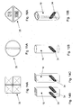
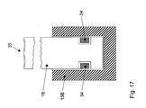
- the device according to the invention is characterized by a displacement bulkhead to be moved onto the matrix grid for portioning the moldable mass, wherein the displacement barrier comprises side boundaries which correspond to the lateral boundaries of the matrix grid.
- the moldable mass is pre-portioned by the displacement bulkhead, wherein in addition the material overhangs on the matrix grid are largely completely displaced into the receiving spaces of the matrix grid and the matrix grid then forms a completely enclosed space around the individual masses, which subsequently has correspondingly adjustable volumes Press through the tools pressing down in the die grid.
- the moldable mass is pre-portioned by the displacement bulkhead, wherein in addition the material overhangs on the matrix grid are largely completely displaced into the receiving spaces of the matrix grid and the matrix grid then forms a completely enclosed space around the individual masses, which subsequently has correspondingly adjustable volumes Press through the tools pressing down in the die grid.
- smooth surface structures and complicated geometries of the moldings can be realized.
- the side boundaries of the displacement bulkhead are aligned with the lateral boundaries of the matrix grid.
- the thickness of the side boundaries of the die grid corresponds in particular to the thickness of the side boundaries of the displacement partition.
- the side boundaries of the displacement bulkhead and the lateral boundaries of the matrix grid have end faces which at least partially come to rest when the displacement bulkhead and the matrix grid are moved towards each other completely.
- the respective end faces have in particular the same geometry.
- the matrix grid may comprise a square, rectangular, diamond-shaped or circular grid. The same grid is then formed by the side boundaries of the displacement bulkhead, so that the end faces each match.
- the transition from the end faces to the side boundaries of the die grid and / or the displacement partition is rounded off or bevelled.
- the tool can be guided from the side boundaries of the displacement bulkhead into the receiving space.
- the displacement bulkhead can thus fulfill a dual function. On the one hand, it serves to portion the moldable mass. On the other hand, it serves as a guide for the tool.
- a further die-side tool for the at least one receiving space can be guided from the opposite side of the displacement-side tool into the receiving space. In this way, the moldable mass can be pressed in this receiving space from two sides.
- the die grid in particular a plurality of receiving spaces is formed, each associated with a displacement-side tool and a die-side tool.
- the displacement bulkhead-side tools and / or the die-side tools can be mounted in a respective tool carrier. They are particularly secured floating in the tool carrier.
- the tools can be cooled and / or heated in particular for certain moldable masses.
- the displacement bulkhead is coupled to the tool carrier for the displacement bulkhead-side tools.
- the displacement bulkhead is in particular movable relative to the tool carrier against the force of at least one spring.
- At least one tool carrier is movable along a guideway having a forming section in which a constant pressure is exerted by the tools on the portions of the mouldable mass located in the receiving spaces over a distance.
- the shaping section of the guideway runs in particular in a straight line.
- the device according to the invention can be used in particular for molding masses which require a long pressure holding time. Namely, the maximum pressure of the tools can be exerted over the entire distance of the forming section of the guideway.
- this shaping section can be selected to be long enough to realize any desired pressure holding times.
- the residence time of the mass in the section in which it is compressed is thus adjustable.
- the tool carrier is held in particular via a slotted guide in the guideway. Furthermore, a separate guideway may be provided for the tool carrier of the displacement bulkhead-side tools and the tool carrier for the die-side tools.
- At least one tool carrier along the guideway at least partially runs on guide rollers, wherein at least in the forming section of the guideway, the guide rollers with respect to their distance to the tool carrier of displacement-side tools adjustable.
- a molding pressure can be set according to the mass properties to be molded.
- the volumes to be set of the different masses to be pressed are adjusted by means of the height-adjustable die grid.
- tolerances of the guideway in the forming section can be compensated.
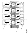
- a cooling section of the guideway in which cool the pressed moldings in the die grid.
- a sampling station for removing one or more moldings can be arranged, which can be fed to a quality control. Thereafter, a removal and camera inspection station for removal and examination of the moldings, a cleaning station for at least the tools, the displacement barrier and the matrix grid and finally a Formungsraumbe harshungs shall be arranged, in which the parts of the device, which come into contact with the moldable mass, be coated to avoid buildup.
- the tool cleaning and the molding space coating can thus be carried out continuously during the ongoing production process.
- an online control during the ongoing manufacturing process and an online mass correction of the moldings are possible.
- an online 100% visual inspection by means of a camera as well as online NIR for various analytical data collections are possible.
- the tool carrier is coupled via a telescopic arm with a rotatable drive unit, so that the tool carrier can be guided over a closed curve.
- the drive unit may be the only driven unit of the device according to the invention.
- a telescopic arm is provided for the tool carrier of the displacement-side tools and the tool carrier of the die-side tools.
- the telescopic arm or the telescopic arms can in particular be mounted so as to be pivotable about an axis tangential with respect to the rotation of the drive unit.
- the length of the telescopic arm is variable.
- the tool carrier is coupled in this case via a horizontal / vertical fork joint with the telescopic arm. In this way, the tool carrier can move radially along the guide track to the drive unit or away from the drive unit.
- the tool carrier can be pivoted upwards and downwards in a horizontal plane of rotation.
- the mouldable mass may in particular be a melt ribbon.
- the device comprises in particular an extruder, wherein the melt ribbon is continuously fed to the die grid.
- a shaping device for smoothing and aligning a melt strand ejected from the extruder to the melt ribbon is arranged between the extruder and the die grid.
- the width of the melt ribbon can be shaped to match the width of the die grid equivalent.
- the thickness of the melt ribbon can thereby be adjusted so that the weight of the individual portions of the mass is adjusted.
- the melt ribbon may comprise several layers of different composition.
- the extruder can be designed in particular for two- or three-component extrusion, wherein the various components can be in different sequences to each other.
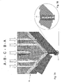
- films and moldings with a product sequence ABA or ABCBA can be formed.
- product sequences may be used for the manufacture of medical products, e.g. used in the manufacture of lingual and sublingual slides / tablets as well as transdermal patches. Such products can be very easily produced on the device according to the invention.
- the mouldable mass may be a bulk material.
- the device according to the invention can in particular compress polymer granules with high recovery force into shaped articles.
- the apparatus of the present invention can be used to process flowable and moldable powdered debris, e.g. in the pharmaceutical, food, cosmetics and hygiene industries.
- a moldable mass is formed and fed to a die grid so that it rests on the end faces of side boundaries of the die grid.
- a displacement bulkhead with side boundaries corresponding to the side boundaries of the die grid is then moved toward the die grid, causing the on-board boundaries displaced from the matrix grid resting part of the moldable mass in the direction of a receiving space formed by the matrix grid between the side boundaries, so that the moldable mass is portioned.
- At least one tool then compresses the portions of the moldable mass in the receiving space.
- the moldable material is supplied in particular continuously to the die grid.
- the displacement bulkhead is moved toward the die grid in such a way that the side boundaries of the displacement bulkhead are aligned with the side boundaries of the die grid.
- the displacement bulkhead is moved towards the die grid until the end faces of the side boundaries of the displacement bulkhead rest at least in part on the end faces of the side boundaries of the die grid.
- the displacement barrier can be moved in particular against the force of at least one spring on the die grid.
- a further die-side tool for the at least one receiving space is guided from the opposite side of the displacement-bulkhead-side tool into the receiving space.
- a multiplicity of receiving spaces can be formed in the die grid.
- pressure is exerted on the moldable material in each receiving space by a displacement-side-side tool and a die-side tool.
- the displacement-bulkhead-side tools and / or the die-side tools are in particular mounted in a respective tool carrier.
- at least one tool carrier is moved along a guideway, which has a shaping section in which a constant pressure is exerted by the tools on the portions of the mouldable mass located in the receiving spaces over a distance.
- the tool carrier is coupled in particular via a telescopic arm with a drive unit. It is moved by means of this drive unit, so that the tool carrier is guided on the guideway via a closed curve.
- a malleable mass is understood to mean any mass which changes its shape under the action of a force.
- a melt strand is formed as a moldable mass which is fed continuously to the matrix grid.
- the melt strand is preferably smoothed and aligned before it is fed to the die grid.
- pulverulent bulk materials can be supplied to the matrix grid as a moldable mass.
- multi-layer extrusion can be used to produce a molded article or a multilayer tablet which has a faster release of active substance from the outer layer and a delayed release of active substance of the inner layer, a multicomponent active ingredient release and realize a cascade-like drug release and by different thickness variations of the individual layers, different release profiles can be realized.
- multilayer moldings for the food, cosmetics and hygiene industries can thus be produced well.
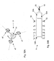
- a per se known extruder 1 can be used.
- the design of the extruder 1 depends on the mass that is to be processed in the extruder 1.
- the masses to be processed may be e.g. be intended for use in the pharmaceutical industry, in the food industry as well as in the cosmetics and hygiene industries.
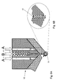
- a plastic melt is produced, which is ejected in the extruder die 10 as a melt strand 11.
- the melt strand 11 can be formed from only one melt.
- a multilayered melt strand 11 may also be formed, e.g. comprises two components A and B in three layers of sequence ABA.
- the extruder 1 may be configured to undergo three component extrusion in five plies of sequence ABCBA.
- the melt strand 11 ejected from the extruder die 10 is fed to a molding station 13 where counter rotating rolls 12A and 12B smooth the melt strand 11 into a melt ribbon 14. Furthermore, in the forming station 13, the width of the melt belt 14 can be set exactly. The width of the melt belt 14 depends on the width of the die grid 19, as will be explained later. The width is created by taperedêtsleitbleche. Corresponding side-prone preform prisms 12B take on the task of mass reduction on the sides of the melt belt.
- the Ausformstation thus the thickness and the width of the melt strip from which the moldings are formed, adjusted exactly. This setting ensures that the masses of the individual blanks are always the same. Furthermore, the height and thus the mass of the molded article to be formed can be adjusted via the thickness of the melt belt 14. In the forming station, a precompression of the moldable mass takes place, which leads to a higher stability of the melt belt 14. The thickness of the melt belt 14 depends on the consistency of the melt, their density and the desired individual weights of the moldings to be produced therefrom.
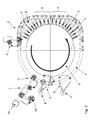
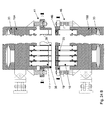
- the forming units 4 are guided on the guide track so that the upper part 4A of the forming unit 4 has approached the lower part 4B of the forming unit 4 behind the molding station 13 for the melt of the extruder 1.
- this forming section A (FIG. 2), they form a unit through which the shaped articles are formed from the melt strip 14.
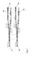
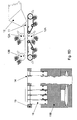
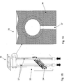
- the forming unit 4 comprises a tool carrier 15 which is divided into an upper tool carrier 15A and a lower tool carrier 15B.
- the upper tool carrier 15A is fixed to an upper telescopic arm 5A
- the lower tool carrier 15B is fixed to a lower telescopic arm 5B.
- the telescopic arms 5A and 5B are arranged in a vertical plane parallel to each other. As already described with reference to FIGS. 1 and 2, they are moved horizontally, wherein they can perform vertical pivoting movements corresponding to the guide track 3.
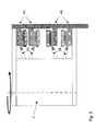
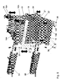
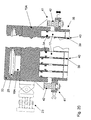
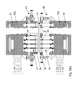
- the upper and lower tool carriers 15A and 15B are disposed adjacent to each other as shown in Fig. 9, as in the case of the forming section A, for example, the upper and lower tool carriers 15A and 15B are aligned with each other by guide rods 22. Lead by These guide rods 22 allow the upper and lower tool carriers 15A and 15B to move further toward each other.
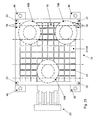
- the upper and lower tool carriers 15A and 15B each include a plurality of guide pins 16A and 16B, respectively, which hold and guide the upper tool carrier 15A in two upper guide tracks 3A.
- the two upper guide tracks 3A are arranged at the same level at different radii with respect to the rotational movement of the drive unit 2.
- the lower guide bolts 16B hold and guide the lower tool carrier 15B in lower guide tracks 3B, respectively.
- three guide pins 16A and 16B are respectively provided for the upper and lower tool carriers 15A and 15B. They hold the two tool carrier parts 15A and 15B in a horizontal position, respectively.
- two guide pins 15A and 15B are respectively disposed on the outer guide track 3A and 3B, and the single guide pins 16A and 16B on the inner track 3A and 3B, respectively, for safe cornering of the tool carrier 15 receive.
- the upper and lower tool carriers 15A and 15B receive the same number of identical tools 17 and 18, respectively. Further, between the upper tool carrier 15A and the lower tool carrier 15B, a die grid 19 and a displacement barrier 38 are arranged, as will be explained later in detail. Both the die grid 19 and the displacement barrier 38 are guided by means of the guide rods 22.
Landscapes
- Engineering & Computer Science (AREA)
- Mechanical Engineering (AREA)
- Extrusion Moulding Of Plastics Or The Like (AREA)
Priority Applications (4)
| Application Number | Priority Date | Filing Date | Title |
|---|---|---|---|
| EP06024451A EP1925442A1 (fr) | 2006-11-24 | 2006-11-24 | Appareil et procédé de moulage haute performance suivant un parcours rotatif |
| US12/514,980 US8277212B2 (en) | 2006-11-24 | 2007-11-23 | High power rotational cycle moulding method and device |
| PCT/EP2007/062735 WO2008062055A1 (fr) | 2006-11-24 | 2007-11-23 | Procédé et dispositif de moulage à cycles de rotation à haut rendement |
| EP07822833.5A EP2081759B1 (fr) | 2006-11-24 | 2007-11-23 | Procédé et dispositif de moulage à cycles de rotation à haut rendement |
Applications Claiming Priority (1)
| Application Number | Priority Date | Filing Date | Title |
|---|---|---|---|
| EP06024451A EP1925442A1 (fr) | 2006-11-24 | 2006-11-24 | Appareil et procédé de moulage haute performance suivant un parcours rotatif |
Publications (1)
| Publication Number | Publication Date |
|---|---|
| EP1925442A1 true EP1925442A1 (fr) | 2008-05-28 |
Family
ID=38232109
Family Applications (2)
| Application Number | Title | Priority Date | Filing Date |
|---|---|---|---|
| EP06024451A Withdrawn EP1925442A1 (fr) | 2006-11-24 | 2006-11-24 | Appareil et procédé de moulage haute performance suivant un parcours rotatif |
| EP07822833.5A Not-in-force EP2081759B1 (fr) | 2006-11-24 | 2007-11-23 | Procédé et dispositif de moulage à cycles de rotation à haut rendement |
Family Applications After (1)
| Application Number | Title | Priority Date | Filing Date |
|---|---|---|---|
| EP07822833.5A Not-in-force EP2081759B1 (fr) | 2006-11-24 | 2007-11-23 | Procédé et dispositif de moulage à cycles de rotation à haut rendement |
Country Status (3)
| Country | Link |
|---|---|
| US (1) | US8277212B2 (fr) |
| EP (2) | EP1925442A1 (fr) |
| WO (1) | WO2008062055A1 (fr) |
Families Citing this family (1)
| Publication number | Priority date | Publication date | Assignee | Title |
|---|---|---|---|---|
| EP1925441A1 (fr) | 2006-11-24 | 2008-05-28 | Abbott GmbH & Co. KG | Appareil et procédé pour former des moulages à partir d'une masse à mouler |
Citations (7)
| Publication number | Priority date | Publication date | Assignee | Title |
|---|---|---|---|---|
| GB568223A (en) * | 1943-09-24 | 1945-03-22 | Henry Manners Kerfoot | Improvements in machines for forming tablets or other articles from powdered material by compression |
| DE2830479A1 (de) * | 1978-07-11 | 1980-01-24 | Schlosser & Co Gmbh | Verfahren und vorrichtung zum fuellen einer form zur herstellung von formlingen aus beton o.dgl. |
| EP0328793A1 (fr) * | 1988-01-22 | 1989-08-23 | INTERCOS ITALIA S.p.A. | Machine pour la production d'emballages pour produits cosmétiques sous forme de poudre et emballage obtenu |
| RU2041825C1 (ru) * | 1992-07-13 | 1995-08-20 | Александр Юрьевич Кем | Ротационный автомат для прессования порошков |
| WO1996035566A1 (fr) * | 1995-05-09 | 1996-11-14 | Fuisz Technologies, Ltd. | Procede et appareil permettant de former des unites galeniques par compression dans l'emballage du produit |
| EP1020285A2 (fr) * | 1998-12-28 | 2000-07-19 | Sumitomo Special Metals Co., Ltd. | Procédé et appareil pour l' alimentation en poudre à base d' alliage de métal en terre-rare |
| WO2003086741A1 (fr) * | 2002-04-04 | 2003-10-23 | Glaxo Group Limited | Procede et appareil de fabrication d'un produit sous forme de comprime |
Family Cites Families (19)
| Publication number | Priority date | Publication date | Assignee | Title |
|---|---|---|---|---|
| FR330819A (fr) | 1903-04-01 | 1903-08-26 | Internat Fuel Company | Machine perfectionnée pour fabriquer des briquettes |
| GB321748A (en) | 1928-08-27 | 1929-11-21 | Frederick Cooke | Improvements in the manufacture of tablets or cubes for stock food, and in machines therefor |
| US2829756A (en) * | 1955-10-14 | 1958-04-08 | Gercke Ferdinand | Transfer mechanism for plastic articles |
| US3332367A (en) * | 1965-07-15 | 1967-07-25 | Upjohn Co | Apparatus for making tablets |
| BE754721A (fr) | 1969-08-12 | 1971-02-11 | Verrieres Appliquees S E V A S | Machine pour le formage de corps creux en matiere plastique |
| US4086045A (en) * | 1972-10-25 | 1978-04-25 | Bellaplast Gmbh | Apparatus for the manufacture of thin-walled shaped articles of thermoplastic material |
| SU599993A1 (ru) | 1976-10-11 | 1978-03-30 | Ждановский Филиал Специального Проектно-Технологического Бюро Медицинской Промышленности | Роторна машина |
| US4420300A (en) * | 1980-08-13 | 1983-12-13 | Maryland Cup Corporation | Continuous rotary thermo-forming systems and apparatus of the pressure assist, plug assist and match mold type |
| DE3612211A1 (de) * | 1986-04-11 | 1987-10-15 | Basf Ag | Kontinuierliches verfahren zum tablettieren |
| DE3714031A1 (de) * | 1987-04-27 | 1988-11-10 | Fette Wilhelm Gmbh | Rundlauf-tablettiermaschine |
| CH671730A5 (fr) | 1987-06-25 | 1989-09-29 | Nestle Sa | |
| DE3830355A1 (de) | 1988-09-07 | 1990-03-15 | Basf Ag | Verfahren zur herstellung von pharmazeutischen tabletten |
| DE3830353A1 (de) * | 1988-09-07 | 1990-03-15 | Basf Ag | Verfahren zur kontinuierlichen herstellung von festen pharmazeutischen formen |
| US5648033A (en) * | 1993-09-10 | 1997-07-15 | Fuisz Technologies Ltd. | Method and apparatus for retaining a formed compression dosage unit within a die cavity |
| JP3133899B2 (ja) | 1994-07-07 | 2001-02-13 | 株式会社三共製作所 | 錠剤製造方法およびその装置 |
| US6106262A (en) | 1997-12-25 | 2000-08-22 | Metropolitan Computing Corporation | Press simulation apparatus |
| DE19855328A1 (de) | 1998-12-01 | 2000-06-08 | Henkel Kgaa | Tablettenpresse |
| DE10152289B4 (de) | 2001-10-23 | 2006-03-23 | Sollich Kg | Verfahren und Vorrichtung zum Herstellen eines Formkörpers aus gekochter Zuckermasse in einer Form |
| EP1925441A1 (fr) | 2006-11-24 | 2008-05-28 | Abbott GmbH & Co. KG | Appareil et procédé pour former des moulages à partir d'une masse à mouler |
-
2006
- 2006-11-24 EP EP06024451A patent/EP1925442A1/fr not_active Withdrawn
-
2007
- 2007-11-23 US US12/514,980 patent/US8277212B2/en not_active Expired - Fee Related
- 2007-11-23 EP EP07822833.5A patent/EP2081759B1/fr not_active Not-in-force
- 2007-11-23 WO PCT/EP2007/062735 patent/WO2008062055A1/fr not_active Ceased
Patent Citations (7)
| Publication number | Priority date | Publication date | Assignee | Title |
|---|---|---|---|---|
| GB568223A (en) * | 1943-09-24 | 1945-03-22 | Henry Manners Kerfoot | Improvements in machines for forming tablets or other articles from powdered material by compression |
| DE2830479A1 (de) * | 1978-07-11 | 1980-01-24 | Schlosser & Co Gmbh | Verfahren und vorrichtung zum fuellen einer form zur herstellung von formlingen aus beton o.dgl. |
| EP0328793A1 (fr) * | 1988-01-22 | 1989-08-23 | INTERCOS ITALIA S.p.A. | Machine pour la production d'emballages pour produits cosmétiques sous forme de poudre et emballage obtenu |
| RU2041825C1 (ru) * | 1992-07-13 | 1995-08-20 | Александр Юрьевич Кем | Ротационный автомат для прессования порошков |
| WO1996035566A1 (fr) * | 1995-05-09 | 1996-11-14 | Fuisz Technologies, Ltd. | Procede et appareil permettant de former des unites galeniques par compression dans l'emballage du produit |
| EP1020285A2 (fr) * | 1998-12-28 | 2000-07-19 | Sumitomo Special Metals Co., Ltd. | Procédé et appareil pour l' alimentation en poudre à base d' alliage de métal en terre-rare |
| WO2003086741A1 (fr) * | 2002-04-04 | 2003-10-23 | Glaxo Group Limited | Procede et appareil de fabrication d'un produit sous forme de comprime |
Also Published As
| Publication number | Publication date |
|---|---|
| US20100072666A1 (en) | 2010-03-25 |
| US8277212B2 (en) | 2012-10-02 |
| EP2081759A1 (fr) | 2009-07-29 |
| WO2008062055A1 (fr) | 2008-05-29 |
| EP2081759B1 (fr) | 2019-01-02 |
Similar Documents
| Publication | Publication Date | Title |
|---|---|---|
| EP2081758B1 (fr) | Procédé et dispositif de moulage d'ébauches à partir d'une matière malléable | |
| DE3012704C2 (de) | Maschine zum Druck- oder Spritzgießen von Verbundformlingen | |
| EP2789239B1 (fr) | Dispositif et procédé de fabrication de produits moulés en forme de boule | |
| EP0244849B1 (fr) | Dispositif à granuler à cylindre creux perforé | |
| DE3820320C2 (fr) | ||
| DE1604331C2 (de) | Vorrichtung zum Zuteilen und kontrollierten Absetzen genau dosierter Mengen eines plastifizierten Kunststoffes | |
| DE19538255A1 (de) | Einspritzgießverfahren und Einspritzgießeinheit für langfaserverstärkten thermoplastischen Kunststoff | |
| DE60302562T2 (de) | Vorrichtung zum pressformen von kunststoffartikeln | |
| EP0461365B1 (fr) | Procédé et appareil pour alimenter un moule de compression en matière plastique | |
| EP0361123A2 (fr) | Procédé de fabrication de récipients en matière thermoplastique, remplis de fluide ainsi que tête d'extrusion | |
| DE3743650A1 (de) | Verfahren und vorrichtung zum herstellen eines mehrschichten konfektproduktes sowie konfektprodukt | |
| EP4232275B1 (fr) | Unité de remplissage pour presse rotative et procédé de fourniture d'une presse rotative optimisée | |
| EP3081089B1 (fr) | Dispositif et procédé destinés à former des produits alimentaires | |
| EP2081759B1 (fr) | Procédé et dispositif de moulage à cycles de rotation à haut rendement | |
| DE19936828A1 (de) | Düsenanordnung, Düsenträger und Vorrichtung zum Extrudieren teigiger Massen | |
| EP2746026A2 (fr) | Dispositif et procédé de fabrication de préformes en matière synthétique à partir d'une matière synthétique thermoplastique | |
| EP3959058B1 (fr) | Unité de moulage par injection pour une machine de moulage par injection pour la transformation de matières plastiques | |
| WO2012163795A1 (fr) | Procédé pour façonner et faire refroidir une masse de fromage fondue préalablement chaude et par conséquent coulante | |
| EP1132002B1 (fr) | Procédé et dispositif de fabrication de morceaux de pâte arrondis de même dimensions | |
| EP2514328A2 (fr) | Dispositif destiné à extruder des masses d'aliments | |
| DE102009014589A1 (de) | Extrusionsvorrichtung zur Verarbeitung und/oder Aufbereitung von Zusammensetzungen | |
| DE102019203284A1 (de) | Vorrichtung zur Aufbereitung von thermoplastischem Restpulver | |
| EP0228616A2 (fr) | Procédé et dispositif de fabrication de corps creux en matériaux thermoplastiques | |
| EP2164468B1 (fr) | Procédé de production d'une forme galénique de médicament | |
| EP4232274B1 (fr) | Unité de remplissage pour presse rotative et procédé de production de presse rotative optimisée |
Legal Events
| Date | Code | Title | Description |
|---|---|---|---|
| PUAI | Public reference made under article 153(3) epc to a published international application that has entered the european phase |
Free format text: ORIGINAL CODE: 0009012 |
|
| AK | Designated contracting states |
Kind code of ref document: A1 Designated state(s): AT BE BG CH CY CZ DE DK EE ES FI FR GB GR HU IE IS IT LI LT LU LV MC NL PL PT RO SE SI SK TR |
|
| AX | Request for extension of the european patent |
Extension state: AL BA HR MK RS |
|
| AKX | Designation fees paid | ||
| STAA | Information on the status of an ep patent application or granted ep patent |
Free format text: STATUS: THE APPLICATION IS DEEMED TO BE WITHDRAWN |
|
| 18D | Application deemed to be withdrawn |
Effective date: 20081129 |
|
| REG | Reference to a national code |
Ref country code: DE Ref legal event code: 8566 |