EP1925479B1 - Porte de véhicule - Google Patents
Porte de véhicule Download PDFInfo
- Publication number
- EP1925479B1 EP1925479B1 EP07120444A EP07120444A EP1925479B1 EP 1925479 B1 EP1925479 B1 EP 1925479B1 EP 07120444 A EP07120444 A EP 07120444A EP 07120444 A EP07120444 A EP 07120444A EP 1925479 B1 EP1925479 B1 EP 1925479B1
- Authority
- EP
- European Patent Office
- Prior art keywords
- vehicle door
- sealing
- door
- connecting flange
- vehicle
- Prior art date
- Legal status (The legal status is an assumption and is not a legal conclusion. Google has not performed a legal analysis and makes no representation as to the accuracy of the status listed.)
- Ceased
Links
- 238000007789 sealing Methods 0.000 claims description 102
- 239000003566 sealing material Substances 0.000 claims description 7
- 239000004033 plastic Substances 0.000 claims description 3
- 238000010276 construction Methods 0.000 description 3
- 238000011161 development Methods 0.000 description 3
- 238000009434 installation Methods 0.000 description 3
- 238000000034 method Methods 0.000 description 3
- 230000002093 peripheral effect Effects 0.000 description 3
- 230000015572 biosynthetic process Effects 0.000 description 2
- 238000013461 design Methods 0.000 description 2
- 238000003780 insertion Methods 0.000 description 2
- 230000037431 insertion Effects 0.000 description 2
- 230000014759 maintenance of location Effects 0.000 description 2
- 230000002787 reinforcement Effects 0.000 description 2
- 230000003014 reinforcing effect Effects 0.000 description 2
- XLYOFNOQVPJJNP-UHFFFAOYSA-N water Substances O XLYOFNOQVPJJNP-UHFFFAOYSA-N 0.000 description 2
- 230000000712 assembly Effects 0.000 description 1
- 238000000429 assembly Methods 0.000 description 1
- 238000005452 bending Methods 0.000 description 1
- 238000010586 diagram Methods 0.000 description 1
- 230000000694 effects Effects 0.000 description 1
- 230000010354 integration Effects 0.000 description 1
- 230000002452 interceptive effect Effects 0.000 description 1
- 238000012986 modification Methods 0.000 description 1
- 230000004048 modification Effects 0.000 description 1
- 238000000465 moulding Methods 0.000 description 1
- 239000002243 precursor Substances 0.000 description 1
- 238000002360 preparation method Methods 0.000 description 1
- 230000001681 protective effect Effects 0.000 description 1
- 238000003856 thermoforming Methods 0.000 description 1
- 238000003466 welding Methods 0.000 description 1
Images
Classifications
-
- B—PERFORMING OPERATIONS; TRANSPORTING
- B60—VEHICLES IN GENERAL
- B60J—WINDOWS, WINDSCREENS, NON-FIXED ROOFS, DOORS, OR SIMILAR DEVICES FOR VEHICLES; REMOVABLE EXTERNAL PROTECTIVE COVERINGS SPECIALLY ADAPTED FOR VEHICLES
- B60J5/00—Doors
- B60J5/04—Doors arranged at the vehicle sides
- B60J5/06—Doors arranged at the vehicle sides slidable; foldable
-
- B—PERFORMING OPERATIONS; TRANSPORTING
- B60—VEHICLES IN GENERAL
- B60J—WINDOWS, WINDSCREENS, NON-FIXED ROOFS, DOORS, OR SIMILAR DEVICES FOR VEHICLES; REMOVABLE EXTERNAL PROTECTIVE COVERINGS SPECIALLY ADAPTED FOR VEHICLES
- B60J10/00—Sealing arrangements
- B60J10/20—Sealing arrangements characterised by the shape
- B60J10/24—Sealing arrangements characterised by the shape having tubular parts
- B60J10/248—Sealing arrangements characterised by the shape having tubular parts having two or more tubular cavities, e.g. formed by partition walls
-
- B—PERFORMING OPERATIONS; TRANSPORTING
- B60—VEHICLES IN GENERAL
- B60J—WINDOWS, WINDSCREENS, NON-FIXED ROOFS, DOORS, OR SIMILAR DEVICES FOR VEHICLES; REMOVABLE EXTERNAL PROTECTIVE COVERINGS SPECIALLY ADAPTED FOR VEHICLES
- B60J10/00—Sealing arrangements
- B60J10/80—Sealing arrangements specially adapted for opening panels, e.g. doors
- B60J10/86—Sealing arrangements specially adapted for opening panels, e.g. doors arranged on the opening panel
- B60J10/87—Sealing arrangements specially adapted for opening panels, e.g. doors arranged on the opening panel with additional seals on the panel side
Definitions
- the invention relates to a vehicle door for closing a door opening provided in a vehicle frame, the vehicle door having body panels, an inner panel facing the vehicle interior in installation position and an outer panel facing away from the vehicle interior in the installed position, which are firmly connected to one another and define a cavity.
- the body panels of a vehicle door of the type mentioned are usually deep-drawn and have, deep-drawn, an outwardly open interior.
- the body panels are arranged to form the cavity with their interiors swept each other and connected. This is for example from the EP 1 057 673 B1 or the EP 1 275 539 A1 seen.
- each to be formed body panels are generally designed so that the interior to the outside and the interior laterally delimiting side walls widen conically, whereby the body panel receives a trough-like basic shape , A forming work to be done depends essentially on the degree of deformation, in particular on the depth of the interior spaces to be created. Likewise, the mold release is made difficult with increasing interior depth.
- a vehicle door which consists of an outer module, which essentially has an outer door panel with a circumferential region in the peripheral reinforcement region, and an inner subframe, which also has a circumferential reinforcing region consists.
- Outer assembly and subframe are partially flat on the reinforcing regions and are connected by releasable connection means such as screws or rivets.
- connection area a door seal is arranged to cover the connection means.
- the connection between outer assembly and subframe is optimized to allow the assembly and disassembly of the two pre-assembled assemblies without damaging them. For a one-piece door, however, the preparation of the connection is too expensive.
- the invention is therefore based on the object to provide a vehicle door of the type mentioned, which can be produced with less effort.
- the cavity of the vehicle door can be designed so that undercuts with respect to a Entformungscardi perpendicular to the larger side surface of the outer panel or the inner panel are possible without the undercut, the deformation of the individual body panels is at least made more difficult by the undercuts as molding areas perpendicular are introduced to the larger side surface of the end plate.
- a conventional outer panel and inner panel have a cross-sectional shape having in principle U-shaped with short legs as bent portions, the legs towards their free ends are slightly tapered apart.
- the front plate is fully laterally connected to the inner panel and the outer panel, so that the cavity is completely separated at least from the end plate to a surrounding space. This simplifies the construction of the front plate.
- the face plate for its connection to the inner panel and the outer panel edge connection areas and outer panel and inner panel edge connecting portions comprise and the connection areas and Connecting portions overlap in a connection position and / or at least partially abut each other flat.
- the connecting sections and connecting regions can be glued, soldered or welded together, for example.
- connecting regions and connecting sections extend in the connecting position with their free ends away from the cavity, wherein the connecting regions and / or the respectively associated connecting sections are bent over and form a common connecting flange in the connecting position. Since the face plate can be fully connected to the inner panel or to the outer panel, the connection flange can surround the end panel at the edge completely and in a ring-like manner. Thanks to their extension direction away from the cavity, the connecting flanges are easily accessible from the outside, for example, for the purpose of producing their connection from the connection region and the connection section.
- connection areas may be bent to bear against the connecting portion of the respective associated sheet to a lateral extent.
- direction of the longitudinal extension of the connection portions may be equal to that of the connection portions.
- the bending over of the connection areas and / or the connection sections can take place with the deep-drawing of the end plate or the outer panel and / or the inner panel.
- the connecting flange is arranged on the narrow side of the vehicle door.
- the connecting flange extends in a direction of extension substantially perpendicular to the end plate.
- the connecting flange may have an outer connecting flange and an inner connecting flange in the installed position. Inner and outer connecting flanges can in this case run substantially vertically in the installed position.
- the two connecting flanges end to its longitudinal extension in installation position by an upper connecting flange and a lower connecting flange to be connected to a preferably closed flange.
- the flange in its course preferably follows the profile of the end plate and remains in its flange height, ie in its extension away from the face plate, preferably approximately equal.
- the connecting flange may extend approximately in or against the direction of travel or with a larger path component in or parallel to a larger side surface of the vehicle door.
- the connecting flange is structurally not interfering and can, as explained below, be provided for other functions.
- the end plate extends between the connecting flanges completely or almost completely in a plane which simplifies the construction of the car door.
- the face plate may be connected to the body panels adjacent thereto to form the outer connecting flange and the inner connecting flange.
- the same has a sealing device for its sealing in the door opening.
- the connecting flange may be adapted for receiving sealing elements of the sealing device and / or the sealing elements may be adapted to the connecting flange.
- the sealing elements preferably have a sealing material, such as rubber or plastic, a longitudinal body with longitudinal air chambers for elastic and sealing engagement with a sealing surface provided on a vehicle frame part or on an adjacent vehicle door and are preferably extruded with a receiving longitudinal groove for the associated connecting flange. More preferably, the sealing elements with the receiving longitudinal groove in a plug-in position on the connecting flange can be plugged or pushed.
- the sealing elements can be applied to the connecting flange such that they cover it almost completely or completely in its longitudinal extension, preferably parallel to the end plate and / or in the direction preferably perpendicular to the end plate.
- a per se known, preferably U-shaped spring element for receiving the respective connecting flange is integrated in the receiving longitudinal groove, which is preferably open to the outside with the receiving longitudinal groove.
- the spring element can be arranged so that it runs with its legs parallel to the inner side walls of the receiving longitudinal groove and is open towards the groove opening. Spring element may form the side walls of the receiving longitudinal groove.
- the spring element can be coextruded with the sealing element or the sealing material can be extruded via the spring element, wherein the spring element is hereinafter preferably embedded in the sealing material. The extruded sealing material may also be brought over and connected to the spring element.
- the sealing element on the connecting flange may be arranged on a groove side surface of the receiving longitudinal flexible retaining projections which project through the receiving groove and rest in the insertion position laterally under tension on the connecting flange.
- the retaining projections preferably project through the receiving groove with a path portion away from the interior.
- the longitudinal air chambers can serve in particular the vertical sealing elements of the water discharge. This allows the integration of the water guide on the front side of the sliding door in the sealing system.
- the sealing elements may form a preferably closed sealing ring.
- a extruded as a precursor sealing strip suitably cut to length and glued to the end of the sealing ring.
- the sealing ring is adapted in its course to the flange ring.
- the sealing ring can be brought as a whole over the sealing ring or mounted on this.
- the front plate is connected only with the formation of the outer connecting flange and the inner connecting flange with the body panels adjacent thereto
- for the formation of the annular flange connecting pieces may be provided, the adjacent ends of connect both connecting flanges. These can be glued or vulcanized with the ends.
- the connecting pieces can be mounted, pushed or plugged on a carrier and / or in a receptacle of the vehicle door.
- the outer connecting flange is arranged in the extension direction by an amount in front of the inner connecting flange.
- the amount may be equal to, about equal to or slightly larger than the extent of the inner connecting flange in the direction of extent. Since this overlap the two connecting flange in the direction perpendicular to a larger side surface of the vehicle door or connect to each other, a stepped toward the passenger compartment sealing of the vehicle door on the vehicle frame or on an adjacent door can be done.
- the outer and inner connecting flange or opposing connecting flange with a small path portion are arranged perpendicular to the extension direction inclined to each other. As a result, the positioning of the end plate can be facilitated before its connection to the body panels. Furthermore, it can be realized that the connecting flanges do not extend perpendicularly to the sealing surface assigned to it but rather in a preferably small inclination thereto.
- the connecting flange can be welded, preferably spot-welded.
- the inner panel and / or the outer panel may each be bent in a peripheral end portion to the narrow side.
- the end portion of the inner panel and / or the outer panel in a first region may form a portion of the narrow side of the vehicle door and be connected in a second region with the end plate to form at least a portion of the connecting flange.
- the second region may form the connecting portion which, as described above, can be bent path-wise away from the cavity, at least with a path component, to form a common connecting flange with the connecting region of the end plate.
- the respective end portion may include an angle of 60 ° to 120 °, preferably 75 ° to 105 °, or more preferably 85 ° to 95 °, with the larger side surface connected thereto.
- the amount can be determined by which the outer connecting flange is arranged in the extension direction in front of the inner connecting flange.
- the invention further comprises a vehicle door system having a vehicle frame with a door opening and a vehicle door according to one of the previously described embodiments and variations, wherein the vehicle door is movable in a closing direction from an open position into the door opening into a closed position.
- the door opening can be limited statically with respect to the body by means of vehicle frame parts or partially with respect to the body by an adjacent second vehicle door.
- the latter is given, for example, in a known manner with a missing central pillar or B-pillar, whereby a single rear in the direction of travel or X-direction of the vehicle and a front in the direction of travel door opening are combined to an opposite the individual door openings expanded total door opening.
- the vehicle door may be lockable in the closed position by means of a locking device.
- the vehicle door can be pivoted and / or displaced into the door opening in the closing direction.
- the arranged on a narrow side end plate may preferably be positioned so that it has at least one path portion and / or an area in the closing direction.
- the vehicle door is designed as a sliding door, which is displaceable in a closing direction along a non-linear relative to the vehicle frame sliding path from the open position to the closed position.
- the front plate may be arranged on the rear narrow side in the closing direction of the vehicle door.
- sliding doors are usually arranged on vehicle sides parallel to the direction of travel or displaceable in the x-direction of the vehicle and are closed in the direction of travel in the direction of travel rear sliding doors and against the direction of travel at the front in the direction of sliding doors, so that the larger side surfaces or the sliding door runs parallel to the side surface of the body and the sliding door is integrated in the closed position in the body.
- This is usually, as claimed here, provided on the rear narrow side sealing elements, which may have the configuration described above.
- the vehicle door designed as a sliding door can be displaceable via guide means with guide rails.
- a rear guide rail in the closing direction in which the sliding door is slidably mounted with a rear end in the closing direction, an S-shaped curve having a rear end in the closing direction end portion which is arranged approximately parallel to the larger side surface of the sliding door in the closed position.
- approximately parallel is meant a positive or negative deviation of a few degrees, so that the rear end portion can be out with a small proportion of path to the vehicle interior or out with a small path portion to the outside.
- the face plate in the closed position against a pillar preferably against a B-pillar, the vehicle frame or against a side surface of an adjacent second vehicle door seal.
- It can thus be provided with at least one sealing surface for sealing engagement with the sealing elements of the vehicle door in its closed position, wherein the sealing surface is provided on a vehicle frame part or on a narrow side of an adjacent door, in the closed position the associated sealing flange of the vehicle door to be sealed lies opposite with the sealing element.
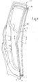
- FIG. 2 shows a perspective side view of a vehicle door F embodied as a sliding door 1 for closing a door opening 2 provided in a vehicle frame (not shown).
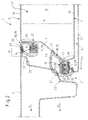
- FIG. 2 and FIG. 3 is a simplified and schematic horizontal and vertical sectional view through a part of a vehicle door system S with the sliding door 1 in a section AA or BB, respectively FIG. 1 shown.
- FIG. 2a shows a detail enlargement IIa according to FIG. 2
- In the Figures 2 and 3 closes the sliding door 1 in a closed position shown here, the door opening 2 and connects to an adjacent side door 3 at.
- B-pillar is provided so that the door opening is closed together by the sliding door 1 and the swing door 3.
- the side door 3 is designed here as a swing door, the in FIG. 2 is shown in a closed position, with its pivot axis outside in the FIG. 2 shown partial view of the vehicle door system S is arranged and in the FIG. 2 shown portion of the side door 3 is pivoted into the door opening 2 inside.
- the sliding door 1 has an inner panel 4 facing the vehicle interior in an installed position and an outer panel 5 facing away from the vehicle interior as well as a front panel 7 for delimiting a cavity 8 on a narrow side 6 of the sliding door 1 as a further body panel.
- the face plate 7 is firmly connected laterally and fully with the inner panel 4 and the outer panel 5.
- the clearer presentation of the invention half, is the sliding door 1 in FIG. 1 shown without outer panel.
- the sliding door 1 is connected via a guide device, not shown here, with guide rails in a closing direction s from an open position not shown here into an in FIG. 1 displaced closed position displaced.
- a guide device not shown here
- guide rails in a closing direction s from an open position not shown here into an in FIG. 1 displaced closed position displaced.
- the sliding door 1 is guided with its end portion 9 on the rear end portion approximately parallel to the larger side surface 10 and thus, when installing the sliding door 1 as the direction f rear side door, in the direction of travel f, which is then approximately equal to the closing direction s.
- This has the consequence that the narrow side 6 is guided with the front plate 7 when reaching the closed position perpendicular or almost perpendicular to the side door 3 or in FIG. 2 is guided.
- the face plate 7 is bent edge side to connecting portions 11.
- the inner panel 4 and the outer panel 5 are each bent to form connecting sections 12, which extend away from the cavity 8 in the extension direction e and, in the connection position shown here, lie flat against one another.
- the extension direction e here corresponds approximately to the direction of travel f or the closing direction s.
- the connecting portions 11 and connecting portions 12 are spot-welded together to form a common connecting flange 14, 15.
- the spot welding itself is in the sketch drawn as a basic sketch in FIG. 2 not specifically reproduced to show the relative position of connecting portions 11 and connecting portions 12 clearer.
- connection flange has an outer connecting flange 14 facing away from the passenger compartment in the installed position and an inner connecting flange 15 facing the passenger compartment in the installed position, these connecting flanges 14, 15 in FIG FIG. 2 are cut. Further, the inner connecting flange 15 and the outer connecting flange 14 are connected endwise to their longitudinal extent in the installed position by an upper connecting flange 16 and a lower connecting flange 17, so that the interconnected connecting flanges 14-17 have a closed flange shape.
- the connecting flange 14, 15 as part of a sealing device of the sliding door 1 in the door opening 3 a the connecting flange 14, 15, 16, 17 adapted, annularly closed sealing ring 19 attached.
- the sealing element 18 is guided to seal the sliding door 1 against a sealing profile 20 with sealing surfaces 21 laterally on the front side door 3 and would have to be represented in a realistic representation of the closed position of the sliding door 1 corresponding deformed.
- the sealing element 18 is shown in the schematic diagrams in FIG Figures 2 and 3 undeformed, wherein the deformable volume of the sealing element 18 is the area of the sealing element 18 which projects into the sealing profile 20.
- the sealing elements 18 are extruded from a sealing material such as rubber or plastic to a longitudinal body 22 with longitudinal air chambers 23 for elastic and sealing engagement with the respectively provided sealing surface 21.
- the sealing elements 18 are made with a receiving longitudinal groove 24 for attaching the sealing elements 18 to the associated connecting flange 14, 15, wherein the sealing elements 18 are shown in a plug-in position, in the these are positioned on the connecting flange 15 by means of the receiving longitudinal groove 24.
- a U-shaped spring element 25 is provided, which is embedded in the sealing material of the sealing element 18 and which reinforces a secure hold of the sealing element 18 on the connecting flange 14, 15.
- inner panel 4 and outer panel 5 are each bent in a peripheral end portion 27 to the narrow side 6, wherein the end portions 27 each in a first region 28 a portion of the narrow side 6 of the sliding door. 1 and in a second region 29 forms the connecting portion 12, which, welded together with the connecting portion 11 of the end plate 7, the inner connecting flange 15 and the outer connecting flange 14 is formed.
- the connecting flanges 14, 15 are offset from the inside or the outside in each case toward the middle of the narrow side 6.
- the front side door 3 also has on its outer side 30 an overlap region 31 which extends counter to the vehicle direction f and in the closed position of the side door 3 and the sliding door 1 covers and secures the outer connecting flange 14 with the sealing element 18 fitted thereon, in particular in the section. in which the sealing element 18 acts on its associated sealing surface 21 and thus the actual sealing process takes place.
- the outer connecting flange 14 is arranged in the closing direction s or in the direction of extent e in front of the inner connecting flange 15, wherein the sealing profile 20 is adapted to the side door 3 in a correspondingly stepped manner is.
- the sealing of the sliding door 1 takes place on its narrow side 6 from outside to inside in steps which are offset in the direction of travel f to each other.
- opposite connecting flanges 14,15 are arranged inclined to each other by a small angle amount.
- the face plate 7 is connected to form the extending away from the cavity 8 and approximately in the closing direction s connecting flanges 14, 15 with the inner panel 4 and the outer panel 5, which is easily accessible from the outside.
- the connecting flanges 14, 15 also serve as a simple carrier of the plug-in sealing elements 18, which surround the end plate 7 in an annular manner. This creates a double seal of the sliding door 1 in the region of the end plate.
- a sealing effect by the voltage applied to the sealing surfaces 21 sealing elements 19 is structurally improved by further measures by the outer connecting flange 14 is disposed in the closing direction in front of the inner connecting flange 15 and thus takes place in the direction of the outer panel 5 to the inner panel 4 a stepped seal. Furthermore, the two connecting flanges 14,15 are not arranged on the edge of the narrow side 6, but towards its center. Further, the overlapping area 31 of the side door 3, on which the sealing element 19 of the outer connecting flange 14 seals in the closed position on the inside, covers this sealing element in a protective manner.
- an interior cover 32 is provided, which is simultaneously sealed by the plugged onto the inner connecting flange 15 sealing member 19 in the direction of travel f to the side door 3 through.
Landscapes
- Engineering & Computer Science (AREA)
- Mechanical Engineering (AREA)
- Seal Device For Vehicle (AREA)
- Body Structure For Vehicles (AREA)
Claims (14)
- Porte de véhicule (F) pour la fermeture d'une ouverture de porte (2) prévue dans un châssis de véhicule, la porte de véhicule (F) présentant des tôles de carrosserie, une tôle interne (4) tournée, dans la position d'installation, vers l'intérieur du véhicule et une tôle externe (5) opposée, dans la position d'installation, à l'intérieur du véhicule, lesquelles sont connectées fixement l'une à l'autre et délimitent une cavité (8), une tôle frontale (7) étant prévue pour limiter la cavité (8) au moins au niveau d'un côté étroit (6) de la porte de véhicule (F) en tant que tôle de carrosserie supplémentaire, la tôle frontale (7) étant connectée fixement à la tôle externe (5) et à la tôle interne (4), et la tôle frontale (7), pour sa connexion à la tôle interne (4) et à la tôle externe (5), comprenant des régions de connexion (11) du côté des bords, et la tôle externe (5) et la tôle interne (4) comprenant des portions de connexion (12) du côté des bords, et les régions de connexion (11) et les portions de connexion (12) se chevauchant dans une position de connexion et/ou s'appliquant au moins en partie à plat l'une contre l'autre,
caractérisée en ce que
les régions de connexion (11) et les portions de connexion (12) s'étendent dans la position de connexion avec leurs extrémités libres à l'écart de la cavité (8), les régions de connexion (11) et/ou les portions de connexion (12) qui leurs sont respectivement associées étant recourbées et constituant dans la position de connexion des brides de connexion communes (14, 15). - Porte de véhicule (F) selon la revendication 1,
caractérisée en ce que
la tôle frontale (7) est connectée sur tout son pourtour latéralement à la tôle interne (4) et à la tôle externe (5). - Porte de véhicule (F) selon la revendication 1 ou 2,
caractérisée en ce que
la bride de connexion (14, 15) est disposée sur le côté étroit (6) de la porte de véhicule (F) et s'étend dans une direction d'étendue (e) essentiellement perpendiculaire à la tôle frontale (7), la bride de connexion (14, 15), dans la position d'installation, étant une bride de connexion externe (14) et/ou une bride de connexion interne (15). - Porte de véhicule (F) selon la revendication 3,
caractérisée en ce que
la bride de connexion interne (15) et la bride de connexion externe (14) sont connectées à l'extrémité de leurs étendues longitudinales dans la position d'installation par une bride de connexion supérieure (16) et une bride de connexion inférieure (17) pour former une bride annulaire. - Porte de véhicule (F) selon l'une quelconque des revendications précédentes,
caractérisée en ce qu'il est prévu dans l'ouverture de la porte (2) un dispositif d'étanchéité pour l'étanchéification de la porte de véhicule (F), et en ce que la bride de connexion (14, 15) est réalisée pour recevoir des éléments d'étanchéité (18) du dispositif d'étanchéité. - Porte de véhicule (F) selon la revendication 5,
caractérisée en ce que
les éléments d'étanchéité (19) présentent un matériau d'étanchéité tel que du caoutchouc ou du plastique pour former un corps oblong (22) avec des chambres d'air longitudinales (23) pour l'application élastique et hermétique contre une surface d'étanchéité (21) prévue sur une partie de châssis du véhicule ou sur une porte de véhicule adjacente (F), et en ce que les éléments d'étanchéité (19) sont extrudés avec une rainure longitudinale de réception (24) pour la bride de connexion associée (14, 15), les éléments d'étanchéité (19) pouvant être enfichés ou poussés avec la rainure longitudinale de réception (24) dans une position enfichée sur la bride de connexion (14, 15). - Porte de véhicule (F) selon la revendication 5 ou 6,
caractérisée en ce que
les éléments d'étanchéité (18) forment une bague d'étanchéité (19). - Porte de véhicule (F) selon l'une quelconque des revendications précédentes,
caractérisée en ce que
la bride de connexion (14, 15) est soudée, notamment soudée par point. - Porte de véhicule (F) selon l'une quelconque des revendications précédentes,
caractérisée en ce que
la tôle interne (4) et/ou la tôle externe (5) sont recourbées à chaque fois dans une portion d'extrémité du côté des bords (27) vers le côté étroit (6), et en ce que la portion d'extrémité (27) forme dans une première région une portion du côté étroit (6) de la porte de véhicule (F) et dans une deuxième région est connectée à la tôle frontale (7). - Système de porte de véhicule (S) qui présente un châssis de véhicule avec une ouverture de porte (2) et une porte de véhicule (F) selon l'une quelconque des revendications précédentes, dans lequel la porte de véhicule (F) peut être déplacée dans une direction de fermeture (s) d'une position ouverte dans l'ouverture de la porte (2) dans une position fermée.
- Système de porte de véhicule (S) selon la revendication 10,
caractérisé en ce que
la porte de véhicule (F) est une porte coulissante (1) qui peut être coulissée d'avant en arrière dans une direction de fermeture (s) le long d'une course de coulissement non linéaire par rapport au châssis du véhicule, entre la position ouverte et la position fermée, la tôle frontale (7) s'appliquant hermétiquement dans la position fermée contre un montant, de préférence un montant B, du châssis du véhicule, ou contre une face latérale (10) d'une deuxième porte de véhicule (F) adjacente. - Système de porte de véhicule (S) selon la revendication 11,
caractérisé en ce que
la porte coulissante (1) peut être coulissée par le biais d'un dispositif de guidage avec des rails de guidage et en ce qu'un rail de guidage arrière dans la direction de fermeture (s), dans lequel la porte coulissante (1) est montée de manière coulissante avec une région d'extrémité arrière (9) dans la direction de fermeture (s), présente une allure en forme de S avec une portion d'extrémité arrière (27) dans la direction de fermeture (s), qui est disposée approximativement parallèlement à la plus grande face latérale (10) de la porte coulissante (1) dans la position fermée. - Système de porte de véhicule (S) selon la revendication 11 ou 12,
caractérisé en ce que
la tôle frontale (7) s'applique de manière hermétique dans la position fermée contre un montant, notamment un montant B du châssis du véhicule ou contre une face latérale (10) d'une deuxième porte de véhicule (F) adjacente. - Système de porte de véhicule (S) selon l'une quelconque des revendications 10 à 13, comprenant une porte de véhicule (F) selon l'une quelconque des revendications 5 à 9,
caractérisé par
un profilé d'étanchéité (20) avec au moins une face d'étanchéité (21) pour l'application hermétique contre les éléments d'étanchéité (18) de la porte de véhicule (F) dans sa position fermée, la face d'étanchéité étant prévue sur une partie de châssis de véhicule ou sur un côté étroit (6) d'une porte adjacente, qui est opposé (e) à la tôle frontale (7) dans la position fermée.
Applications Claiming Priority (1)
| Application Number | Priority Date | Filing Date | Title |
|---|---|---|---|
| DE102006055817A DE102006055817A1 (de) | 2006-11-27 | 2006-11-27 | Fahrzeugtür |
Publications (3)
| Publication Number | Publication Date |
|---|---|
| EP1925479A2 EP1925479A2 (fr) | 2008-05-28 |
| EP1925479A3 EP1925479A3 (fr) | 2008-07-30 |
| EP1925479B1 true EP1925479B1 (fr) | 2011-03-16 |
Family
ID=39166942
Family Applications (1)
| Application Number | Title | Priority Date | Filing Date |
|---|---|---|---|
| EP07120444A Ceased EP1925479B1 (fr) | 2006-11-27 | 2007-11-12 | Porte de véhicule |
Country Status (4)
| Country | Link |
|---|---|
| US (1) | US7703837B2 (fr) |
| EP (1) | EP1925479B1 (fr) |
| CN (1) | CN101191401B (fr) |
| DE (2) | DE102006055817A1 (fr) |
Families Citing this family (15)
| Publication number | Priority date | Publication date | Assignee | Title |
|---|---|---|---|---|
| US8550537B2 (en) * | 2010-11-05 | 2013-10-08 | Honda Motor Co., Ltd. | Automotive vehicle passage seal |
| JP2012116454A (ja) * | 2010-11-11 | 2012-06-21 | Asmo Co Ltd | 車両用ドアトリム |
| US20120151843A1 (en) * | 2010-12-20 | 2012-06-21 | Tesla Motors, Inc. | Vehicle Door Secondary Sealing System |
| US8328269B2 (en) * | 2011-01-28 | 2012-12-11 | GM Global Technology Operations LLC | Articulating trim closeout panel for opposing hinged doors |
| JP6595837B2 (ja) * | 2015-07-30 | 2019-10-23 | 西川ゴム工業株式会社 | ドアウェザーストリップ |
| JP2017077850A (ja) * | 2015-10-22 | 2017-04-27 | 本田技研工業株式会社 | ドアシール構造 |
| JP2017210164A (ja) * | 2016-05-26 | 2017-11-30 | トヨタ自動車株式会社 | 車両用ドア構造 |
| JP6586244B2 (ja) * | 2016-10-18 | 2019-10-02 | 本田技研工業株式会社 | ドア構造 |
| JP6588998B2 (ja) * | 2018-01-25 | 2019-10-09 | 本田技研工業株式会社 | スライドドア |
| CN109552017A (zh) * | 2018-12-04 | 2019-04-02 | 爱驰汽车有限公司 | 一种汽车 |
| JP7415262B2 (ja) * | 2019-09-26 | 2024-01-17 | スズキ株式会社 | 車両用サイドドア構造 |
| CN111591118A (zh) * | 2020-05-21 | 2020-08-28 | 上海荣南科技有限公司 | 一种适用于对开式车门b柱的门缝密封条 |
| CN112319196A (zh) * | 2020-11-13 | 2021-02-05 | 东风柳州汽车有限公司 | 一种增强挡水性能的车门外密封条结构 |
| US20230313574A1 (en) * | 2022-03-30 | 2023-10-05 | Honda Motor Co., Ltd. | Dual sliding doors with asymmetric latch configuration and overlapping edges |
| CN115042606B (zh) * | 2022-07-20 | 2025-04-15 | 浙江吉利控股集团有限公司 | 车辆车身和车辆 |
Family Cites Families (13)
| Publication number | Priority date | Publication date | Assignee | Title |
|---|---|---|---|---|
| JPS5934924A (ja) * | 1982-08-23 | 1984-02-25 | Nissan Motor Co Ltd | スライドドア車におけるガイドレ−ルの取付構造 |
| JPS5976981U (ja) * | 1982-11-15 | 1984-05-24 | 株式会社東芝 | 冷蔵庫の断熱扉 |
| DE9321411U1 (de) | 1993-04-29 | 1997-11-13 | Opel Adam Ag | Schiebetür, insbesondere für Kraftfahrzeuge |
| DE4314115A1 (de) * | 1993-04-29 | 1994-11-03 | Opel Adam Ag | Schiebetür, insbesondere für Kraftfahrzeuge |
| JP2000177392A (ja) * | 1998-12-16 | 2000-06-27 | Aisin Seiki Co Ltd | スライドドア給電機構 |
| FR2794490B1 (fr) * | 1999-06-02 | 2001-08-03 | Peugeot Citroen Automobiles Sa | Dispositif anti-pincement pour porte coulissante de vehicule automobile |
| DE60223111T2 (de) * | 2001-07-04 | 2008-08-07 | Mazda Motor Corp. | Türstruktur für Fahrzeuge |
| GB0313364D0 (en) * | 2003-06-10 | 2003-07-16 | Gencorp Property Inc | Sealing strip for a closure member |
| DE10334143B4 (de) | 2002-07-25 | 2013-04-18 | Brose Fahrzeugteile Gmbh & Co. Kommanditgesellschaft, Coburg | Kraftfahrzeugtür |
| US6641205B1 (en) * | 2002-10-23 | 2003-11-04 | Honda Giken Kogyo Kabushiki Kaisha | Vehicle door sealing assembly |
| DE502004010724D1 (de) * | 2003-07-24 | 2010-03-25 | Brose Fahrzeugteile | Kraftfahrzeugtür |
| JP4330564B2 (ja) * | 2005-08-05 | 2009-09-16 | 豊田合成株式会社 | 自動車ドアのシール構造 |
| FR2892345B1 (fr) * | 2005-10-21 | 2010-09-10 | Heuliez | Porte sans cadre de vehicule automobile comprenant une vitre, vehicule automobile et procede de reglage de l'inclinaison de la vitre d'une telle porte |
-
2006
- 2006-11-27 DE DE102006055817A patent/DE102006055817A1/de not_active Withdrawn
-
2007
- 2007-11-12 DE DE502007006719T patent/DE502007006719D1/de active Active
- 2007-11-12 EP EP07120444A patent/EP1925479B1/fr not_active Ceased
- 2007-11-26 US US11/944,664 patent/US7703837B2/en active Active
- 2007-11-26 CN CN2007101875532A patent/CN101191401B/zh not_active Expired - Fee Related
Also Published As
| Publication number | Publication date |
|---|---|
| US7703837B2 (en) | 2010-04-27 |
| DE502007006719D1 (de) | 2011-04-28 |
| CN101191401A (zh) | 2008-06-04 |
| EP1925479A2 (fr) | 2008-05-28 |
| EP1925479A3 (fr) | 2008-07-30 |
| DE102006055817A1 (de) | 2008-05-29 |
| US20080122250A1 (en) | 2008-05-29 |
| CN101191401B (zh) | 2013-05-08 |
Similar Documents
| Publication | Publication Date | Title |
|---|---|---|
| EP1925479B1 (fr) | Porte de véhicule | |
| DE102016200475B3 (de) | Fahrzeugtürbaugruppe mit Einführbereichen an rahmenseitigen Führungselementen für ein flächenbündiges Scheibenkonzept und Montageverfahren | |
| DE69311456T2 (de) | Formteil für Tür | |
| DE3639936A1 (de) | Anordnung fuer die befestigung einer kraftfahrzeugscheibe in der zarge einer kraftfahrzeugkarosserie | |
| DE69020326T2 (de) | Dichtung für Kraftfahrzeugtür. | |
| EP1176044B1 (fr) | Elément composite pour carrosseries de véhicule, ainsi que procédé et dispositif pour sa fabrication | |
| EP2188143A1 (fr) | Baguette couvre-joint | |
| EP1086882B1 (fr) | Elément composite pour carrosseries de véhicule | |
| EP0968862B2 (fr) | Fenêtre coulissante pour véhicule automobile | |
| EP1807277A1 (fr) | Bande de matiere destinee a l'etancheite, au revetement ou au guidage | |
| EP2129506B1 (fr) | Procédé de production d'un système d'étanchéité, notamment pour automobile, comprenant un élément d'étanchéité et un support, et système d'étanchéité correspondant | |
| DE4325501A1 (de) | Kraftfahrzeug mit wenigstens einer Türfensterscheibe | |
| DE102019126860A1 (de) | Deckel zum Verschließen einer Öffnung in einer Fahrzeugkarosserie | |
| EP1177969B1 (fr) | Structure brute de carrosserie pour véhicule | |
| DE60008263T3 (de) | Kraftfahrzeugtür und Verfahren zu deren Zusammenbau | |
| DE10157001C1 (de) | Dichtungssystem für eine Tür, insbesondere an einem Fahrzeug | |
| DE10135406A1 (de) | Fahrzeugdach mit einer Dachöffnung | |
| DE102005042123A1 (de) | Tür für ein Kraftfahrzeug | |
| DE69820403T2 (de) | Neue Kraftfahrzeugtürrahmen und Herstellungsverfahren | |
| DE102005024527A1 (de) | Vorrichtung zur Zwangsentlüftung eines Innenraums eines Kraftfahrzeugs und Verfahren zu deren Herstellung | |
| EP1522445B1 (fr) | Joint d'étanchéité pour une porte de véhicule | |
| DE102005045298A1 (de) | Dichtungsprofil für Kraftfahrzeugtüren | |
| AT9443U1 (de) | Viertüriges kraftfahrzeug mit türdichtungssystem für rahmenlose türen | |
| DE3902938C1 (en) | Sectional door | |
| DE19847657C1 (de) | Profildichtung sowie zugehörige Schiebetür mit entsprechender Profildichtung |
Legal Events
| Date | Code | Title | Description |
|---|---|---|---|
| PUAI | Public reference made under article 153(3) epc to a published international application that has entered the european phase |
Free format text: ORIGINAL CODE: 0009012 |
|
| AK | Designated contracting states |
Kind code of ref document: A2 Designated state(s): AT BE BG CH CY CZ DE DK EE ES FI FR GB GR HU IE IS IT LI LT LU LV MC MT NL PL PT RO SE SI SK TR |
|
| AX | Request for extension of the european patent |
Extension state: AL BA HR MK RS |
|
| PUAL | Search report despatched |
Free format text: ORIGINAL CODE: 0009013 |
|
| AK | Designated contracting states |
Kind code of ref document: A3 Designated state(s): AT BE BG CH CY CZ DE DK EE ES FI FR GB GR HU IE IS IT LI LT LU LV MC MT NL PL PT RO SE SI SK TR |
|
| AX | Request for extension of the european patent |
Extension state: AL BA HR MK RS |
|
| RIC1 | Information provided on ipc code assigned before grant |
Ipc: B60J 5/06 20060101ALI20080624BHEP Ipc: B60J 5/04 20060101AFI20080319BHEP |
|
| 17P | Request for examination filed |
Effective date: 20090130 |
|
| 17Q | First examination report despatched |
Effective date: 20090307 |
|
| AKX | Designation fees paid |
Designated state(s): DE FR GB |
|
| GRAP | Despatch of communication of intention to grant a patent |
Free format text: ORIGINAL CODE: EPIDOSNIGR1 |
|
| GRAS | Grant fee paid |
Free format text: ORIGINAL CODE: EPIDOSNIGR3 |
|
| GRAA | (expected) grant |
Free format text: ORIGINAL CODE: 0009210 |
|
| AK | Designated contracting states |
Kind code of ref document: B1 Designated state(s): DE FR GB |
|
| REG | Reference to a national code |
Ref country code: GB Ref legal event code: FG4D Free format text: NOT ENGLISH |
|
| REF | Corresponds to: |
Ref document number: 502007006719 Country of ref document: DE Date of ref document: 20110428 Kind code of ref document: P |
|
| REG | Reference to a national code |
Ref country code: DE Ref legal event code: R096 Ref document number: 502007006719 Country of ref document: DE Effective date: 20110428 |
|
| PLBE | No opposition filed within time limit |
Free format text: ORIGINAL CODE: 0009261 |
|
| STAA | Information on the status of an ep patent application or granted ep patent |
Free format text: STATUS: NO OPPOSITION FILED WITHIN TIME LIMIT |
|
| 26N | No opposition filed |
Effective date: 20111219 |
|
| REG | Reference to a national code |
Ref country code: DE Ref legal event code: R097 Ref document number: 502007006719 Country of ref document: DE Effective date: 20111219 |
|
| REG | Reference to a national code |
Ref country code: FR Ref legal event code: PLFP Year of fee payment: 9 |
|
| REG | Reference to a national code |
Ref country code: FR Ref legal event code: PLFP Year of fee payment: 10 |
|
| REG | Reference to a national code |
Ref country code: FR Ref legal event code: PLFP Year of fee payment: 11 |
|
| REG | Reference to a national code |
Ref country code: FR Ref legal event code: PLFP Year of fee payment: 12 |
|
| PGFP | Annual fee paid to national office [announced via postgrant information from national office to epo] |
Ref country code: DE Payment date: 20181015 Year of fee payment: 12 |
|
| PGFP | Annual fee paid to national office [announced via postgrant information from national office to epo] |
Ref country code: GB Payment date: 20181025 Year of fee payment: 12 Ref country code: FR Payment date: 20181017 Year of fee payment: 12 |
|
| REG | Reference to a national code |
Ref country code: DE Ref legal event code: R119 Ref document number: 502007006719 Country of ref document: DE |
|
| GBPC | Gb: european patent ceased through non-payment of renewal fee |
Effective date: 20191112 |
|
| PG25 | Lapsed in a contracting state [announced via postgrant information from national office to epo] |
Ref country code: DE Free format text: LAPSE BECAUSE OF NON-PAYMENT OF DUE FEES Effective date: 20200603 Ref country code: GB Free format text: LAPSE BECAUSE OF NON-PAYMENT OF DUE FEES Effective date: 20191112 Ref country code: FR Free format text: LAPSE BECAUSE OF NON-PAYMENT OF DUE FEES Effective date: 20191130 |