EP1925508B1 - Ensemble de module airbag - Google Patents
Ensemble de module airbag Download PDFInfo
- Publication number
- EP1925508B1 EP1925508B1 EP07020889A EP07020889A EP1925508B1 EP 1925508 B1 EP1925508 B1 EP 1925508B1 EP 07020889 A EP07020889 A EP 07020889A EP 07020889 A EP07020889 A EP 07020889A EP 1925508 B1 EP1925508 B1 EP 1925508B1
- Authority
- EP
- European Patent Office
- Prior art keywords
- airbag module
- connection
- pin
- connection element
- plug
- Prior art date
- Legal status (The legal status is an assumption and is not a legal conclusion. Google has not performed a legal analysis and makes no representation as to the accuracy of the status listed.)
- Not-in-force
Links
- 238000003780 insertion Methods 0.000 claims abstract description 61
- 230000037431 insertion Effects 0.000 claims abstract description 61
- 229920001971 elastomer Polymers 0.000 claims description 5
- 239000000806 elastomer Substances 0.000 claims description 5
- 238000010304 firing Methods 0.000 claims 1
- 230000005489 elastic deformation Effects 0.000 description 4
- 238000009434 installation Methods 0.000 description 4
- 238000004519 manufacturing process Methods 0.000 description 4
- 230000002441 reversible effect Effects 0.000 description 3
- 240000006829 Ficus sundaica Species 0.000 description 2
- 150000001875 compounds Chemical class 0.000 description 2
- 230000001419 dependent effect Effects 0.000 description 2
- 238000006073 displacement reaction Methods 0.000 description 2
- 238000012423 maintenance Methods 0.000 description 2
- 230000000712 assembly Effects 0.000 description 1
- 238000000429 assembly Methods 0.000 description 1
- 238000011161 development Methods 0.000 description 1
- 230000018109 developmental process Effects 0.000 description 1
- 238000012986 modification Methods 0.000 description 1
- 230000004048 modification Effects 0.000 description 1
- 238000003466 welding Methods 0.000 description 1
Images

Classifications
-
- B—PERFORMING OPERATIONS; TRANSPORTING
- B60—VEHICLES IN GENERAL
- B60R—VEHICLES, VEHICLE FITTINGS, OR VEHICLE PARTS, NOT OTHERWISE PROVIDED FOR
- B60R21/00—Arrangements or fittings on vehicles for protecting or preventing injuries to occupants or pedestrians in case of accidents or other traffic risks
- B60R21/02—Occupant safety arrangements or fittings, e.g. crash pads
- B60R21/16—Inflatable occupant restraints or confinements designed to inflate upon impact or impending impact, e.g. air bags
- B60R21/20—Arrangements for storing inflatable members in their non-use or deflated condition; Arrangement or mounting of air bag modules or components
- B60R21/205—Arrangements for storing inflatable members in their non-use or deflated condition; Arrangement or mounting of air bag modules or components in dashboards
Definitions
- the present invention relates to an airbag module assembly according to the preamble of claim 1.
- An airbag module includes an airbag that can deploy through the rapidly expanding gas generated by a gas generator to protect vehicle occupants in the event of an accident.
- airbag modules can also be arranged behind a vehicle interior trim part, such as a dashboard (passenger airbag), a part of the headliner (roof airbag) or the interior trim of an A, B or C-pillar (side airbag).
- the DE 103 12 948 A1 of the DE 103 12 947 A1 and the DE 103 25 435 A1 known to attach the airbag module to a cross member of the vehicle body below a dashboard by plug-in, screw or clip connections.
- the attachment to a support of the vehicle body can be complex if it is not easily accessible.
- the connection between the vehicle interior trim part and the carrier of the vehicle body requires a corresponding space for receiving the airbag module, which can not always be made available, especially in the case of roof and side airbags.
- Other positions of a passenger airbag within a dashboard and a passenger-side glove box can limit the available space for the airbag module and complicate a connection to a support of the vehicle body.
- This known from the prior art attachment to a cross member of the vehicle body also requires an additional holding part, which must be secured to the cross member, for example by welding, before the airbag module can be fixed thereto.
- This additional holding part increases the production costs, the total weight as well as the number of parts to be produced, stocked and mounted.
- the object of the present invention is to provide an improved airbag module arrangement.
- an airbag module assembly for a motor vehicle which comprises an airbag module and a vehicle interior trim part.
- the vehicle interior trim part can in particular be a dashboard, an inner lining of an A, B or C pillar of the motor vehicle or a headliner act.
- the airbag module itself is preferably detachably connected by means of a first plug connection and a second connection to the vehicle interior trim part.
- it has a first connection element of the first connector and a third connection element of the second connection, while the vehicle interior trim part has a second connection element and a fourth connection element.
- the first and second connecting elements together form the first connector, while the second connection is formed by the third and fourth connecting element of the airbag module.
- the airbag module according to the invention is attached directly to the vehicle interior trim part and no longer needs to be fixed to a cross member of the vehicle body.
- the assembly of the airbag module is simplified, which now no longer has to be attached to a sometimes difficult to reach cross member of the vehicle body.
- the airbag module can also be accommodated in limited installation spaces, which in particular do not provide any space for a cross member or the like.
- the course of a cross member no longer provide a connection possibility for the airbag module and can therefore be optimized under strength, mounting or similar aspects.
- first connector is particularly easy to install, as to close this connection, only the first and second connection element must be brought into positive engagement with each other, wherein advantageously the second connection element can be arranged easily accessible to the vehicle interior trim part.
- the second connection is designed as a screw connection.
- the third and fourth fastening element in each case as a flange be configured, in which a corresponding blind or through hole is provided.
- One or more screws are passed through the corresponding holes in the flanges and bolted to one of the flanges or a nut.
- the screw connection is aligned substantially perpendicular to an insertion direction of the first connector.
- the first connector fixes the airbag module positively in one or two planes perpendicular to the insertion direction. By screwing in one of these levels, a movement of the airbag module is prevented in the insertion direction, so that this is then fixed in all three spatial directions.
- loads acting on the airbag module can in this way be absorbed mainly by the first or second connection, with a suitable connection being present for each force component.
- this orientation can facilitate assembly, since initially the first connector is positively engaged and the airbag module can be moved in this until the holes of the second screw aligned.
- a bore in the third and / or fourth connecting element can be designed as a slot in a direction substantially perpendicular to the insertion direction. Then the airbag module can be moved in its first connector until these holes are aligned with each other in this direction. Position deviations in the direction perpendicular thereto can then be compensated due to the holes designed as a slot or slots.
- the screw connection is aligned substantially parallel to a weft direction of the airbag module.
- Such a screw connection can also be advantageous from a mounting standpoint, in particular easier to access.
- the second connection is designed as a plug connection. This allows for faster assembly and in particular does not require the use of screws, which can reduce both the weight, the number of parts, the assembly steps and thus the installation time and production costs.
- a second insertion direction of the second connector is aligned substantially parallel to a first insertion direction of the first connector.
- This allows a very simple installation and at the same time a secure fixing of the airbag module: first, the first connector is brought into positive engagement and the airbag module in the first insertion direction until the third and fourth connection element are aligned. Subsequently, the airbag module is pushed back so far in the second insertion direction substantially parallel thereto that the second plug-in connection also comes into positive engagement.
- the first plug connection advantageously also allows pivoting of the airbag module about an axis of rotation substantially perpendicular to this insertion direction. This can be realized, for example, that this connector is designed with some play.
- first and / or second connector may have a certain elasticity, the it allows first the first and subsequent to bring the second connectors with each other.
- the airbag module only has to be pivoted slightly to bring the second connector into alignment. This advantageously reduces the game necessary for this purpose or the elastic deformation required for this purpose in the first plug connection.
- the second plug connection is not yet fixed in the mounted state in the second insertion direction, since the insertion movements are reversible. Therefore, in a preferred embodiment, the first and / or second plug connection comprises an elastic element which biases the airbag module in the insertion direction of the second plug connection. As a result, the airbag module can also be fixed non-positively in the second insertion direction.
- an elastic element for example a spring or an elastomer, bias the airbag module in the second insertion direction and thus counteract a sliding back in this direction and thus a release of the connection.
- the first connector can be moved under elastic deformation of the first connecting element in the first insertion direction, the thus deformed connecting element partially relaxed in the subsequent shift in the second insertion direction and thus biases the second connector also in the second insertion direction.
- first and / or second plug connection comprise a locking element, which defines the airbag module in a locking position offset from a maximum insertion position against movement against the second insertion direction towards the maximum insertion position.
- the first plug-in connection is first brought into a maximum insertion position, and then the airbag module is displaced in the second insertion direction into an offset relative to this maximum insertion position end position.
- the first and / or second plug connection is then fixed by means of the locking element form fit in this direction.
- the above-described elastic element which biases the airbag module in the second insertion direction, can support and relieve the locking element and thus facilitate both the assembly and additionally secure the airbag module in its final position.
- the locking element is movable against a restoring force from the locking position.
- the locking element automatically move against the restoring force from the locking position, so that it automatically returns to the locking position during subsequent displacement in the second insertion direction and the airbag module in the second insertion direction determines form fit.
- the locking element can also be manually brought into the locking position and fixed there.
- a pin can be inserted perpendicular to the second insertion direction.
- Both manually and by a resilient restoring force automatically brought into the locking position locking element can be advantageously removed again from the locked position, which allows disassembly of the airbag module in reverse order, starting with a shift against the second insertion direction until the second connector disengaged comes.
- This advantageously allows a simple release of the airbag module of the vehicle interior trim part, for example, for maintenance purposes, without further tools.
- the first and / or second connector is formed by one or more pins which engage positively in corresponding receptacles.
- the pins may equally be arranged on the airbag module or the vehicle interior trim part.
- the pins of the first and second plug connection can be arranged on the airbag module or on the vehicle interior trim part.
- the pins of the first and the receptacles of the second connector can be arranged on the airbag module or on the vehicle interior trim part.
- the pins can have any shape, which may result in particular from the strength requirements and the desired mounting kinematics.
- round pins can compensate in part for manufacturing tolerances by rotation about their longitudinal axis and facilitate insertion and adjustment.
- Pins with asymmetrical, in particular angular cross sections can additionally lead the insertion movement.
- Long pins allow a particularly good guidance in the insertion direction, while short pins in particular facilitate pivoting about an axis of rotation substantially perpendicular to its longitudinal axis.
- Thick pegs can absorb large forces, while thin pegs can be correspondingly elastic and thus facilitate insertion. In a plurality of pins, the forces to be absorbed distribute advantageous, so that the individual pin be less stressed and can be sized smaller.
- a small number of pins, in particular a pin arrangement with only one pin facilitates insertion into the corresponding receptacle. The fewer pins are provided, the less positional tolerances to each other and the recordings must be complied with.
- an elastic element in particular an elastomer, may be arranged between at least one journal of a journal arrangement of a connection and the receptacle for this journal.
- This elastic element can in particular, as described above, also bias the airbag module in the second insertion direction and thus counteract a release of the attachment.
- Fig. 1 shows an airbag module assembly according to a first embodiment of the present invention with an airbag module 1, which is attached to a dashboard 2 and covered by an airbag cover 9 against a passenger compartment. When opening the airbag (not shown) this breaks through the airbag cover 9 and unfolds in the weft direction. 6
- the airbag module 1 has on its one longitudinal or transverse side a first connecting element in the form of a first pin 3.1, which is inserted into a corresponding first receptacle 3.2. This is formed in the dashboard 2 and forms with the first pin 3.1, a first connector 3, the airbag module 1 in the weft direction 6 and a direction perpendicular thereto (normal to the plane of the Fig. 1 ) determines positively.
- the airbag module 1 On its second longitudinal or transverse side, the airbag module 1 has a third connecting element in the form of a flange 4.1. This is connected by a screw with a fourth connecting element in the form of a flange 4.2, which is formed on the instrument panel 2.
- the flanges 4.1 and 4.2 together form a second screw 4, which defines the airbag module together with the first connector 3 reliably on the instrument panel 2.
- the installation of the airbag module 1 is very simple: first, the first pin 3.1 is inserted into the first receptacle 3.2 and then moved the airbag module until a through hole in the flange 4.1 of the airbag module and a blind hole in the flange 4.2 of the instrument panel are aligned. Then they are screwed together.
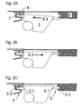
- FIG. 2A - 2C show an airbag module assembly according to a second embodiment of the present invention. Elements that correspond to the first embodiment are designated by the same reference numerals, so that only the differences from the first embodiment will be discussed below.
- Fig. 2C shows the end position of the airbag module 1, while the Fig. 2A, 2B Intermediate steps represent during its assembly.
- a first pin 3.1 of the airbag module 1 (s. Fig. 2C ) introduced into a first receptacle 3.2 in the instrument panel 2 in a first insertion direction 3.3 ( Fig. 2A ).
- an elastic element in the form of an elastomer 7 is compressed in the first insertion direction.
- a locking element 8 is pressed by the first pin 3. 1 from the first receptacle 3.2 and thereby deformed elastically.
- the airbag module about a direction of rotation perpendicular to the first insertion direction 3.3 axis is tilted until a second pin 5.1 (s. Fig. 2C ), which is formed on the second longitudinal side of the airbag module, aligned with a second receptacle 5.2, which is formed in the instrument panel 2.
- the first connector 3 which is formed by the first pin 3.1 and the first receptacle 3.2, a slight game, which allows the tilting of the airbag module 1.
- the first connector is substantially free of play.
- the insertion in the first insertion direction 3.3 and the subsequent tilting of the airbag module 1 takes place here under elastic deformation of the first pin 3.1 and the first recording 3.2.
- the airbag module After aligning the second pin 5.1 to the second receptacle 5.2, the airbag module is displaced in a second insertion direction 5.3, which is substantially parallel to the first insertion direction 3 .3 ( Fig. 2B ).
- the second pin 5.1 engages positively in the second receptacle 5.2 and forms a second connector 5.
- a stop limits the movement in the second insertion direction 5.3 and puts the airbag module in its end position ( Fig. 2C ) firmly.
- the locking element 8 can be manually moved out of its locking position by pressing on an outstanding limb, which causes the airbag module 1 to move counter to the second insertion direction 5.3 and thus disassemble in the reverse order allows for the assembly described above.
- a first or second pin arrangement respectively comprises only one first or second pin 3.1 or 5.1, which is formed in each case on a longitudinal or transverse side of the airbag module 1.
- the first and / or second pin arrangement may also comprise a plurality of first and second pins, which engage in corresponding first and second receptacles.
- the first and / or second pin arrangement can also be formed on the dash panels 2, in which case the airbag module 1 is formed with the corresponding first and second receptacle.
- the first and / or second connection 3, 4 or 5 can also be arranged on a transverse side of the airbag module 1.
Landscapes
- Engineering & Computer Science (AREA)
- Mechanical Engineering (AREA)
- Air Bags (AREA)
Claims (11)
- Dispositif de module de coussin gonflable de sécurité pour un véhicule à moteur, avec un module de coussin gonflable de sécurité (1) et une partie d'habillage intérieur de véhicule, en particulier un tableau de bord (2), dans lequel le module de coussin gonflable de sécurité présente un premier élément d'assemblage (3.1) d'un premier assemblage emboîté (3) et un troisième élément d'assemblage (4.1 ; 5.1) d'un deuxième assemblage (4 ; 5) et dans lequel la partie d'habillage intérieur de véhicule présente un deuxième élément d'assemblage (3.2), qui forme avec le premier élément d'assemblage (3.1) du module de coussin gonflable de sécurité le premier assemblage emboîté (3), et un quatrième élément d'assemblage (4.2 ; 5.2) qui forme avec le troisième élément d'assemblage (4.1 ; 5.1) du module de coussin gonflable de sécurité le deuxième (4 ; 5), caractérisé en ce qu'il est prévu entre au moins un goujon d'un dispositif de goujons d'un assemblage et le logement pour ce goujon un élément élastique, en particulier un élastomère (7), et/ou
en ce que le deuxième assemblage est conformé comme un assemblage vissé (4), auquel cas un trou est percé dans le troisième élément de liaison et/ou le quatrième sous la forme d'un trou oblong dans une direction sensiblement perpendiculaire à la direction d'insertion. - Dispositif de module de coussin gonflable de sécurité selon la revendication 1, caractérisé en ce que l'assemblage vissé (4) est orienté de façon sensiblement perpendiculaire au sens d'insertion (3.3) du premier assemblage emboîté (3).
- Dispositif de module de coussin gonflable de sécurité selon la revendication 2, caractérisé en ce que l'assemblage vissé (4) est orienté de façon sensiblement parallèle à la direction de déclenchement (6) du module de coussin gonflable de sécurité (1).
- Dispositif de module de coussin gonflable de sécurité pour un véhicule à moteur, avec un module de coussin gonflable de sécurité (1) et une partie d'habillage intérieur de véhicule, en particulier un tableau de bord (2), dans lequel le module de coussin gonflable de sécurité présente un premier élément d'assemblage (3.1) d'un premier assemblage emboîté (3) et un troisième élément d'assemblage (4.1 ; 5.1) d'un deuxième assemblage (4 ; 5) et dans lequel la partie d'habillage intérieur de véhicule présente un deuxième élément d'assemblage (3.2), qui forme avec le premier élément d'assemblage (3.1) du module de coussin gonflable de sécurité le premier assemblage emboîté (3), et un quatrième élément d'assemblage (4.2 ; 5.2) qui forme avec le troisième élément d'assemblage (4.1 ; 5.1) du module de coussin gonflable de sécurité le deuxième assemblage (4 ; 5), et dans lequel le deuxième assemblage est conformé comme un assemblage emboîté (5), caractérisé en ce qu'il est prévu entre au moins un goujon d'un dispositif de goujon d'un assemblage et le logement de ce goujon un élément élastique, en particulier un élastomère (7) ; et/ou
en ce que le premier assemblage emboîté et/ou le deuxième (3, 5) comprennent un élément de verrouillage (8) qui fixe, dans une position de verrouillage, le module de coussin gonflable de sécurité dans une position finale décalée par rapport à une position d'insertion maximale afin d'empêcher un déplacement vers la position d'insertion maximale. - Dispositif de module de coussin gonflable de sécurité selon la revendication 4, caractérisé en ce qu'une deuxième direction d'insertion (5.3) du deuxième assemblage emboîté est orientée de façon sensiblement parallèle à une première direction d'insertion (3.3) du premier assemblage emboîté (3).
- Dispositif de module de coussin gonflable de sécurité selon la revendication 5, caractérisé en ce que l'élément élastique (7) précontraint le module de coussin gonflable de sécurité dans la direction d'insertion (3.3, 5.3) du premier assemblage emboîté et/ou du deuxième (3, 5).
- Dispositif de module de coussin gonflable de sécurité selon la revendication 4, caractérisé en ce que l'élément de verrouillage (8) peut être déplacé à partir de la position de verrouillage contre une force de rappel.
- Dispositif de module de coussin gonflable de sécurité selon l'une des revendications 4 à 7, caractérisé en ce que le troisième élément d'assemblage comprend un deuxième dispositif de goujons avec au moins un deuxième goujon (5.1) et le quatrième élément d'assemblage comprend un deuxième logement (5.2) pour le deuxième goujon (5.1) du deuxième dispositif de goujons.
- Dispositif de module de coussin gonflable de sécurité selon l'une des revendications 4 à 7, caractérisé en ce que le quatrième élément d'assemblage comprend un deuxième dispositif de goujons avec au moins un deuxième goujon et le troisième élément d'assemblage comprend un deuxième logement pour les deuxièmes goujons du deuxième dispositif de goujons.
- Dispositif de module de coussin gonflable de sécurité selon l'une des revendications précédentes, caractérisé en ce que le premier élément d'assemblage comprend un premier dispositif de goujons avec au moins un premier goujon (3.1) et le deuxième élément d'assemblage comprend un premier logement (3.2) pour le premier goujon (3.1) du premier dispositif de goujons.
- Dispositif de module de coussin gonflable de sécurité selon l'une des revendications 1 à 9, caractérisé en ce que le deuxième élément d'assemblage comprend un premier dispositif de goujons avec au moins un premier goujon et le premier élément d'assemblage comprend un premier logement pour les premiers goujons du premier dispositif de goujons.
Applications Claiming Priority (1)
| Application Number | Priority Date | Filing Date | Title |
|---|---|---|---|
| DE102006055909A DE102006055909A1 (de) | 2006-11-27 | 2006-11-27 | Airbagmodulanordnung |
Publications (3)
| Publication Number | Publication Date |
|---|---|
| EP1925508A2 EP1925508A2 (fr) | 2008-05-28 |
| EP1925508A3 EP1925508A3 (fr) | 2008-08-13 |
| EP1925508B1 true EP1925508B1 (fr) | 2009-11-25 |
Family
ID=38988034
Family Applications (1)
| Application Number | Title | Priority Date | Filing Date |
|---|---|---|---|
| EP07020889A Not-in-force EP1925508B1 (fr) | 2006-11-27 | 2007-10-25 | Ensemble de module airbag |
Country Status (3)
| Country | Link |
|---|---|
| EP (1) | EP1925508B1 (fr) |
| AT (1) | ATE449708T1 (fr) |
| DE (2) | DE102006055909A1 (fr) |
Families Citing this family (6)
| Publication number | Priority date | Publication date | Assignee | Title |
|---|---|---|---|---|
| DE102007056227A1 (de) * | 2007-11-22 | 2009-06-04 | Continental Automotive Gmbh | Airbag-Satellit |
| DE102012011525A1 (de) * | 2012-06-09 | 2013-12-12 | GM Global Technology Operations LLC (n. d. Gesetzen des Staates Delaware) | Fahrzeug mit einer Instrumententafel undmit einer Airbaganordnung |
| DE102012215840A1 (de) * | 2012-09-06 | 2014-05-28 | Bayerische Motoren Werke Aktiengesellschaft | Kraftfahrzeug mit einem Airbagmodul |
| DE102012215853A1 (de) * | 2012-09-06 | 2014-05-28 | Bayerische Motoren Werke Aktiengesellschaft | Kraftfahrzeug mit einem Airbagmodul |
| FR3020330A1 (fr) * | 2014-04-29 | 2015-10-30 | Peugeot Citroen Automobiles Sa | Conteneur airbag |
| DE102018107995B4 (de) * | 2018-04-05 | 2025-08-21 | Dr. Ing. H.C. F. Porsche Aktiengesellschaft | Anordnung, umfassend ein Airbagmodul und ein Schusskanalgehäuse |
Family Cites Families (6)
| Publication number | Priority date | Publication date | Assignee | Title |
|---|---|---|---|---|
| JP3232855B2 (ja) * | 1994-01-28 | 2001-11-26 | 本田技研工業株式会社 | 車両用エアバッグ装置 |
| JP2001322523A (ja) * | 2000-05-11 | 2001-11-20 | Takata Corp | 助手席用エアバッグ装置及びその設置構造 |
| DE10203286A1 (de) * | 2002-01-29 | 2003-08-14 | Volkswagen Ag | Airbaganordnung in einer Instrumententafel eines Fahrzeuges, insbesondere eines Kraftfahrzeuges |
| JP4158461B2 (ja) * | 2002-09-04 | 2008-10-01 | タカタ株式会社 | 助手席用エアバッグ装置の設置構造 |
| KR100503294B1 (ko) * | 2002-09-05 | 2005-07-25 | 현대모비스 주식회사 | 자동차용 조수석 에어백 모듈 |
| DE10346012B4 (de) * | 2002-12-21 | 2015-06-11 | Volkswagen Ag | Airbaganordnung an einem Fahrzeug, insbesondere an einem Kraftfahrzeug |
-
2006
- 2006-11-27 DE DE102006055909A patent/DE102006055909A1/de not_active Withdrawn
-
2007
- 2007-10-25 DE DE502007002098T patent/DE502007002098D1/de active Active
- 2007-10-25 AT AT07020889T patent/ATE449708T1/de active
- 2007-10-25 EP EP07020889A patent/EP1925508B1/fr not_active Not-in-force
Also Published As
| Publication number | Publication date |
|---|---|
| EP1925508A2 (fr) | 2008-05-28 |
| ATE449708T1 (de) | 2009-12-15 |
| DE502007002098D1 (de) | 2010-01-07 |
| DE102006055909A1 (de) | 2008-05-29 |
| EP1925508A3 (fr) | 2008-08-13 |
Similar Documents
| Publication | Publication Date | Title |
|---|---|---|
| EP2546106B1 (fr) | Adaptateur, module avec adaptateur ainsi que le procédé de montage d'un tel module | |
| DE102010041048B4 (de) | Befestigungssystem | |
| EP1925508B1 (fr) | Ensemble de module airbag | |
| DE102013220574A1 (de) | Verfahren zum Montieren eines Frontendmoduls und eines Frontscheinwerfers an einer Karosserie eines Personenkraftwagens sowie Halteanordnung eines Frontscheinwerfers an einem Frontendmodul | |
| EP2334502B1 (fr) | Mécanisme de verrouillage et sous-ensemble d accouplement côté véhicule d un attelage de remorque | |
| EP1326757A1 (fr) | Support pour la realisation d'un module de portiere | |
| CH711751B1 (de) | Befestigungseinrichtung für ein in Schienen einer Bodenstruktur eines Flugzeuginnenraumes zu befestigendes Bauteil. | |
| DE102011013255B4 (de) | Entriegelungsvorrichtung | |
| EP3650290A1 (fr) | Module de sac gonflage, son procédé de montage ainsi que module de direction doté d'un tel module de sac gonflage | |
| DE102007056671B4 (de) | Befestigungsanordnung | |
| DE102012011750A1 (de) | Befestigungsanordnung | |
| DE69901268T2 (de) | Kraftfahrzeug-Lenksystem | |
| DE102019006074B4 (de) | Knieairbag-befestigungsstruktur | |
| DE102012005509A1 (de) | Verfahren und Vorrichtung zur Montage eines Klappenelements | |
| DE102010016749B4 (de) | Airbaggehäuse eines Airbagsystems und Airbagsystem | |
| DE102016011744B3 (de) | Haltevorrichtung für ein Außenbeplankungselement eines Kraftfahrzeugs, Kraftfahrzeug und Verfahren zum Betätigen einer Haltevorrichtung | |
| DE102009026727A1 (de) | Befestigung von Zierleisten | |
| EP3999415B1 (fr) | Système de fixation pour la fixation d'une pièce, agencement de pièce et aéronef | |
| DE102009033945A1 (de) | Verfahren zur Montage eines Gesamtsystems für ein Fahrzeug | |
| EP2296967B1 (fr) | Élément interface, élément d'équipement intérieur d'avion et procédé de montage d'un élément d'équipement intérieur d'avion | |
| DE102020123291A1 (de) | Befestigungselement zum Befestigen eines Anbauteils im Innenraum eines Kraftfahrzeuges | |
| DE102018205809B4 (de) | Trägerelement zum Befestigen eines Innenverkleidungsteils an einem Bauteil eines Fahrzeugs. | |
| DE102011117953A1 (de) | Anordnung eines Außenanbauelements, insbesondere einer Leuchte, an einem Montageträgerelement eines Kraftwagens | |
| EP3157772B1 (fr) | Système de fixation | |
| DE102020123288B4 (de) | Befestigungselement zum Befestigen eines Anbauteils im Innenraum eines Kraftfahrzeuges |
Legal Events
| Date | Code | Title | Description |
|---|---|---|---|
| PUAI | Public reference made under article 153(3) epc to a published international application that has entered the european phase |
Free format text: ORIGINAL CODE: 0009012 |
|
| AK | Designated contracting states |
Kind code of ref document: A2 Designated state(s): AT BE BG CH CY CZ DE DK EE ES FI FR GB GR HU IE IS IT LI LT LU LV MC MT NL PL PT RO SE SI SK TR |
|
| AX | Request for extension of the european patent |
Extension state: AL BA HR MK RS |
|
| PUAL | Search report despatched |
Free format text: ORIGINAL CODE: 0009013 |
|
| AK | Designated contracting states |
Kind code of ref document: A3 Designated state(s): AT BE BG CH CY CZ DE DK EE ES FI FR GB GR HU IE IS IT LI LT LU LV MC MT NL PL PT RO SE SI SK TR |
|
| AX | Request for extension of the european patent |
Extension state: AL BA HR MK RS |
|
| 17P | Request for examination filed |
Effective date: 20090213 |
|
| 17Q | First examination report despatched |
Effective date: 20090316 |
|
| AKX | Designation fees paid |
Designated state(s): AT BE BG CH CY CZ DE DK EE ES FI FR GB GR HU IE IS IT LI LT LU LV MC MT NL PL PT RO SE SI SK TR |
|
| GRAP | Despatch of communication of intention to grant a patent |
Free format text: ORIGINAL CODE: EPIDOSNIGR1 |
|
| GRAS | Grant fee paid |
Free format text: ORIGINAL CODE: EPIDOSNIGR3 |
|
| GRAA | (expected) grant |
Free format text: ORIGINAL CODE: 0009210 |
|
| AK | Designated contracting states |
Kind code of ref document: B1 Designated state(s): AT BE BG CH CY CZ DE DK EE ES FI FR GB GR HU IE IS IT LI LT LU LV MC MT NL PL PT RO SE SI SK TR |
|
| REG | Reference to a national code |
Ref country code: GB Ref legal event code: FG4D Free format text: NOT ENGLISH |
|
| REG | Reference to a national code |
Ref country code: CH Ref legal event code: EP |
|
| REG | Reference to a national code |
Ref country code: IE Ref legal event code: FG4D |
|
| REF | Corresponds to: |
Ref document number: 502007002098 Country of ref document: DE Date of ref document: 20100107 Kind code of ref document: P |
|
| REG | Reference to a national code |
Ref country code: NL Ref legal event code: VDEP Effective date: 20091125 |
|
| LTIE | Lt: invalidation of european patent or patent extension |
Effective date: 20091125 |
|
| PG25 | Lapsed in a contracting state [announced via postgrant information from national office to epo] |
Ref country code: SE Free format text: LAPSE BECAUSE OF FAILURE TO SUBMIT A TRANSLATION OF THE DESCRIPTION OR TO PAY THE FEE WITHIN THE PRESCRIBED TIME-LIMIT Effective date: 20091125 Ref country code: PT Free format text: LAPSE BECAUSE OF FAILURE TO SUBMIT A TRANSLATION OF THE DESCRIPTION OR TO PAY THE FEE WITHIN THE PRESCRIBED TIME-LIMIT Effective date: 20100325 Ref country code: FI Free format text: LAPSE BECAUSE OF FAILURE TO SUBMIT A TRANSLATION OF THE DESCRIPTION OR TO PAY THE FEE WITHIN THE PRESCRIBED TIME-LIMIT Effective date: 20091125 Ref country code: IS Free format text: LAPSE BECAUSE OF FAILURE TO SUBMIT A TRANSLATION OF THE DESCRIPTION OR TO PAY THE FEE WITHIN THE PRESCRIBED TIME-LIMIT Effective date: 20100325 Ref country code: LT Free format text: LAPSE BECAUSE OF FAILURE TO SUBMIT A TRANSLATION OF THE DESCRIPTION OR TO PAY THE FEE WITHIN THE PRESCRIBED TIME-LIMIT Effective date: 20091125 |
|
| PG25 | Lapsed in a contracting state [announced via postgrant information from national office to epo] |
Ref country code: LV Free format text: LAPSE BECAUSE OF FAILURE TO SUBMIT A TRANSLATION OF THE DESCRIPTION OR TO PAY THE FEE WITHIN THE PRESCRIBED TIME-LIMIT Effective date: 20091125 Ref country code: SI Free format text: LAPSE BECAUSE OF FAILURE TO SUBMIT A TRANSLATION OF THE DESCRIPTION OR TO PAY THE FEE WITHIN THE PRESCRIBED TIME-LIMIT Effective date: 20091125 Ref country code: PL Free format text: LAPSE BECAUSE OF FAILURE TO SUBMIT A TRANSLATION OF THE DESCRIPTION OR TO PAY THE FEE WITHIN THE PRESCRIBED TIME-LIMIT Effective date: 20091125 Ref country code: CY Free format text: LAPSE BECAUSE OF FAILURE TO SUBMIT A TRANSLATION OF THE DESCRIPTION OR TO PAY THE FEE WITHIN THE PRESCRIBED TIME-LIMIT Effective date: 20091125 |
|
| REG | Reference to a national code |
Ref country code: IE Ref legal event code: FD4D |
|
| PG25 | Lapsed in a contracting state [announced via postgrant information from national office to epo] |
Ref country code: RO Free format text: LAPSE BECAUSE OF FAILURE TO SUBMIT A TRANSLATION OF THE DESCRIPTION OR TO PAY THE FEE WITHIN THE PRESCRIBED TIME-LIMIT Effective date: 20091125 Ref country code: DK Free format text: LAPSE BECAUSE OF FAILURE TO SUBMIT A TRANSLATION OF THE DESCRIPTION OR TO PAY THE FEE WITHIN THE PRESCRIBED TIME-LIMIT Effective date: 20091125 Ref country code: NL Free format text: LAPSE BECAUSE OF FAILURE TO SUBMIT A TRANSLATION OF THE DESCRIPTION OR TO PAY THE FEE WITHIN THE PRESCRIBED TIME-LIMIT Effective date: 20091125 Ref country code: IE Free format text: LAPSE BECAUSE OF FAILURE TO SUBMIT A TRANSLATION OF THE DESCRIPTION OR TO PAY THE FEE WITHIN THE PRESCRIBED TIME-LIMIT Effective date: 20091125 Ref country code: BG Free format text: LAPSE BECAUSE OF FAILURE TO SUBMIT A TRANSLATION OF THE DESCRIPTION OR TO PAY THE FEE WITHIN THE PRESCRIBED TIME-LIMIT Effective date: 20100225 Ref country code: EE Free format text: LAPSE BECAUSE OF FAILURE TO SUBMIT A TRANSLATION OF THE DESCRIPTION OR TO PAY THE FEE WITHIN THE PRESCRIBED TIME-LIMIT Effective date: 20091125 Ref country code: ES Free format text: LAPSE BECAUSE OF FAILURE TO SUBMIT A TRANSLATION OF THE DESCRIPTION OR TO PAY THE FEE WITHIN THE PRESCRIBED TIME-LIMIT Effective date: 20100308 |
|
| PG25 | Lapsed in a contracting state [announced via postgrant information from national office to epo] |
Ref country code: CZ Free format text: LAPSE BECAUSE OF FAILURE TO SUBMIT A TRANSLATION OF THE DESCRIPTION OR TO PAY THE FEE WITHIN THE PRESCRIBED TIME-LIMIT Effective date: 20091125 Ref country code: SK Free format text: LAPSE BECAUSE OF FAILURE TO SUBMIT A TRANSLATION OF THE DESCRIPTION OR TO PAY THE FEE WITHIN THE PRESCRIBED TIME-LIMIT Effective date: 20091125 |
|
| PLBE | No opposition filed within time limit |
Free format text: ORIGINAL CODE: 0009261 |
|
| STAA | Information on the status of an ep patent application or granted ep patent |
Free format text: STATUS: NO OPPOSITION FILED WITHIN TIME LIMIT |
|
| PG25 | Lapsed in a contracting state [announced via postgrant information from national office to epo] |
Ref country code: GR Free format text: LAPSE BECAUSE OF FAILURE TO SUBMIT A TRANSLATION OF THE DESCRIPTION OR TO PAY THE FEE WITHIN THE PRESCRIBED TIME-LIMIT Effective date: 20100226 |
|
| 26N | No opposition filed |
Effective date: 20100826 |
|
| PG25 | Lapsed in a contracting state [announced via postgrant information from national office to epo] |
Ref country code: IT Free format text: LAPSE BECAUSE OF FAILURE TO SUBMIT A TRANSLATION OF THE DESCRIPTION OR TO PAY THE FEE WITHIN THE PRESCRIBED TIME-LIMIT Effective date: 20091125 |
|
| BERE | Be: lapsed |
Owner name: GM GLOBAL TECHNOLOGY OPERATIONS, INC. Effective date: 20101031 |
|
| REG | Reference to a national code |
Ref country code: DE Ref legal event code: R081 Ref document number: 502007002098 Country of ref document: DE Owner name: GM GLOBAL TECHNOLOGY OPERATIONS LLC (N. D. GES, US Free format text: FORMER OWNER: GM GLOBAL TECHNOLOGY OPERATIONS, INC., DETROIT, MICH., US Effective date: 20110323 |
|
| PG25 | Lapsed in a contracting state [announced via postgrant information from national office to epo] |
Ref country code: MC Free format text: LAPSE BECAUSE OF NON-PAYMENT OF DUE FEES Effective date: 20101031 |
|
| PG25 | Lapsed in a contracting state [announced via postgrant information from national office to epo] |
Ref country code: BE Free format text: LAPSE BECAUSE OF NON-PAYMENT OF DUE FEES Effective date: 20101031 |
|
| PG25 | Lapsed in a contracting state [announced via postgrant information from national office to epo] |
Ref country code: MT Free format text: LAPSE BECAUSE OF FAILURE TO SUBMIT A TRANSLATION OF THE DESCRIPTION OR TO PAY THE FEE WITHIN THE PRESCRIBED TIME-LIMIT Effective date: 20091125 |
|
| REG | Reference to a national code |
Ref country code: CH Ref legal event code: PL |
|
| PG25 | Lapsed in a contracting state [announced via postgrant information from national office to epo] |
Ref country code: CH Free format text: LAPSE BECAUSE OF NON-PAYMENT OF DUE FEES Effective date: 20111031 Ref country code: LI Free format text: LAPSE BECAUSE OF NON-PAYMENT OF DUE FEES Effective date: 20111031 |
|
| PG25 | Lapsed in a contracting state [announced via postgrant information from national office to epo] |
Ref country code: HU Free format text: LAPSE BECAUSE OF FAILURE TO SUBMIT A TRANSLATION OF THE DESCRIPTION OR TO PAY THE FEE WITHIN THE PRESCRIBED TIME-LIMIT Effective date: 20100526 Ref country code: LU Free format text: LAPSE BECAUSE OF NON-PAYMENT OF DUE FEES Effective date: 20101025 |
|
| PG25 | Lapsed in a contracting state [announced via postgrant information from national office to epo] |
Ref country code: TR Free format text: LAPSE BECAUSE OF FAILURE TO SUBMIT A TRANSLATION OF THE DESCRIPTION OR TO PAY THE FEE WITHIN THE PRESCRIBED TIME-LIMIT Effective date: 20091125 |
|
| REG | Reference to a national code |
Ref country code: AT Ref legal event code: MM01 Ref document number: 449708 Country of ref document: AT Kind code of ref document: T Effective date: 20121031 |
|
| PG25 | Lapsed in a contracting state [announced via postgrant information from national office to epo] |
Ref country code: AT Free format text: LAPSE BECAUSE OF NON-PAYMENT OF DUE FEES Effective date: 20121031 |
|
| PGFP | Annual fee paid to national office [announced via postgrant information from national office to epo] |
Ref country code: DE Payment date: 20131023 Year of fee payment: 7 Ref country code: FR Payment date: 20131009 Year of fee payment: 7 |
|
| PGFP | Annual fee paid to national office [announced via postgrant information from national office to epo] |
Ref country code: GB Payment date: 20141022 Year of fee payment: 8 |
|
| REG | Reference to a national code |
Ref country code: DE Ref legal event code: R119 Ref document number: 502007002098 Country of ref document: DE |
|
| PG25 | Lapsed in a contracting state [announced via postgrant information from national office to epo] |
Ref country code: DE Free format text: LAPSE BECAUSE OF NON-PAYMENT OF DUE FEES Effective date: 20150501 |
|
| REG | Reference to a national code |
Ref country code: FR Ref legal event code: ST Effective date: 20150630 |
|
| PG25 | Lapsed in a contracting state [announced via postgrant information from national office to epo] |
Ref country code: FR Free format text: LAPSE BECAUSE OF NON-PAYMENT OF DUE FEES Effective date: 20141031 |
|
| GBPC | Gb: european patent ceased through non-payment of renewal fee |
Effective date: 20151025 |
|
| PG25 | Lapsed in a contracting state [announced via postgrant information from national office to epo] |
Ref country code: GB Free format text: LAPSE BECAUSE OF NON-PAYMENT OF DUE FEES Effective date: 20151025 |