EP1925509B1 - Distributeur de courant gazeux pour un module d'airbag latéral - Google Patents
Distributeur de courant gazeux pour un module d'airbag latéral Download PDFInfo
- Publication number
- EP1925509B1 EP1925509B1 EP07075907A EP07075907A EP1925509B1 EP 1925509 B1 EP1925509 B1 EP 1925509B1 EP 07075907 A EP07075907 A EP 07075907A EP 07075907 A EP07075907 A EP 07075907A EP 1925509 B1 EP1925509 B1 EP 1925509B1
- Authority
- EP
- European Patent Office
- Prior art keywords
- gas
- airbag module
- holder
- generator
- module according
- Prior art date
- Legal status (The legal status is an assumption and is not a legal conclusion. Google has not performed a legal analysis and makes no representation as to the accuracy of the status listed.)
- Expired - Lifetime
Links
- 239000000463 material Substances 0.000 claims description 2
- 239000002184 metal Substances 0.000 claims description 2
- 238000004512 die casting Methods 0.000 claims 1
- 238000009434 installation Methods 0.000 claims 1
- 239000007789 gas Substances 0.000 description 209
- 230000006378 damage Effects 0.000 description 3
- 239000004744 fabric Substances 0.000 description 3
- 238000012986 modification Methods 0.000 description 3
- 230000004048 modification Effects 0.000 description 3
- 208000027418 Wounds and injury Diseases 0.000 description 2
- 230000015572 biosynthetic process Effects 0.000 description 2
- 238000013461 design Methods 0.000 description 2
- 230000000694 effects Effects 0.000 description 2
- 208000014674 injury Diseases 0.000 description 2
- 241000602850 Cinclidae Species 0.000 description 1
- 238000005452 bending Methods 0.000 description 1
- 238000004891 communication Methods 0.000 description 1
- 230000006870 function Effects 0.000 description 1
- 230000001771 impaired effect Effects 0.000 description 1
- 238000003780 insertion Methods 0.000 description 1
- 230000037431 insertion Effects 0.000 description 1
- 238000011900 installation process Methods 0.000 description 1
- 230000014759 maintenance of location Effects 0.000 description 1
- 230000009993 protective function Effects 0.000 description 1
- 238000012546 transfer Methods 0.000 description 1
- 239000002023 wood Substances 0.000 description 1
Images


Classifications
-
- B—PERFORMING OPERATIONS; TRANSPORTING
- B60—VEHICLES IN GENERAL
- B60R—VEHICLES, VEHICLE FITTINGS, OR VEHICLE PARTS, NOT OTHERWISE PROVIDED FOR
- B60R21/00—Arrangements or fittings on vehicles for protecting or preventing injuries to occupants or pedestrians in case of accidents or other traffic risks
- B60R21/02—Occupant safety arrangements or fittings, e.g. crash pads
- B60R21/16—Inflatable occupant restraints or confinements designed to inflate upon impact or impending impact, e.g. air bags
- B60R21/26—Inflatable occupant restraints or confinements designed to inflate upon impact or impending impact, e.g. air bags characterised by the inflation fluid source or means to control inflation fluid flow
- B60R21/261—Inflatable occupant restraints or confinements designed to inflate upon impact or impending impact, e.g. air bags characterised by the inflation fluid source or means to control inflation fluid flow with means other than bag structure to diffuse or guide inflation fluid
-
- B—PERFORMING OPERATIONS; TRANSPORTING
- B60—VEHICLES IN GENERAL
- B60R—VEHICLES, VEHICLE FITTINGS, OR VEHICLE PARTS, NOT OTHERWISE PROVIDED FOR
- B60R21/00—Arrangements or fittings on vehicles for protecting or preventing injuries to occupants or pedestrians in case of accidents or other traffic risks
- B60R21/02—Occupant safety arrangements or fittings, e.g. crash pads
- B60R21/16—Inflatable occupant restraints or confinements designed to inflate upon impact or impending impact, e.g. air bags
- B60R21/20—Arrangements for storing inflatable members in their non-use or deflated condition; Arrangement or mounting of air bag modules or components
- B60R21/217—Inflation fluid source retainers, e.g. reaction canisters; Connection of bags, covers, diffusers or inflation fluid sources therewith or together
- B60R21/2171—Inflation fluid source retainers, e.g. reaction canisters; Connection of bags, covers, diffusers or inflation fluid sources therewith or together specially adapted for elongated cylindrical or bottle-like inflators with a symmetry axis perpendicular to the main direction of bag deployment, e.g. extruded reaction canisters
-
- B—PERFORMING OPERATIONS; TRANSPORTING
- B60—VEHICLES IN GENERAL
- B60R—VEHICLES, VEHICLE FITTINGS, OR VEHICLE PARTS, NOT OTHERWISE PROVIDED FOR
- B60R21/00—Arrangements or fittings on vehicles for protecting or preventing injuries to occupants or pedestrians in case of accidents or other traffic risks
- B60R21/02—Occupant safety arrangements or fittings, e.g. crash pads
- B60R21/16—Inflatable occupant restraints or confinements designed to inflate upon impact or impending impact, e.g. air bags
- B60R21/26—Inflatable occupant restraints or confinements designed to inflate upon impact or impending impact, e.g. air bags characterised by the inflation fluid source or means to control inflation fluid flow
-
- B—PERFORMING OPERATIONS; TRANSPORTING
- B60—VEHICLES IN GENERAL
- B60R—VEHICLES, VEHICLE FITTINGS, OR VEHICLE PARTS, NOT OTHERWISE PROVIDED FOR
- B60R21/00—Arrangements or fittings on vehicles for protecting or preventing injuries to occupants or pedestrians in case of accidents or other traffic risks
- B60R2021/0002—Type of accident
- B60R2021/0006—Lateral collision
-
- B—PERFORMING OPERATIONS; TRANSPORTING
- B60—VEHICLES IN GENERAL
- B60R—VEHICLES, VEHICLE FITTINGS, OR VEHICLE PARTS, NOT OTHERWISE PROVIDED FOR
- B60R21/00—Arrangements or fittings on vehicles for protecting or preventing injuries to occupants or pedestrians in case of accidents or other traffic risks
- B60R21/02—Occupant safety arrangements or fittings, e.g. crash pads
- B60R21/04—Padded linings for the vehicle interior ; Energy absorbing structures associated with padded or non-padded linings
-
- B—PERFORMING OPERATIONS; TRANSPORTING
- B60—VEHICLES IN GENERAL
- B60R—VEHICLES, VEHICLE FITTINGS, OR VEHICLE PARTS, NOT OTHERWISE PROVIDED FOR
- B60R21/00—Arrangements or fittings on vehicles for protecting or preventing injuries to occupants or pedestrians in case of accidents or other traffic risks
- B60R21/02—Occupant safety arrangements or fittings, e.g. crash pads
- B60R21/16—Inflatable occupant restraints or confinements designed to inflate upon impact or impending impact, e.g. air bags
- B60R21/23—Inflatable members
- B60R21/231—Inflatable members characterised by their shape, construction or spatial configuration
- B60R21/23138—Inflatable members characterised by their shape, construction or spatial configuration specially adapted for side protection
-
- B—PERFORMING OPERATIONS; TRANSPORTING
- B60—VEHICLES IN GENERAL
- B60R—VEHICLES, VEHICLE FITTINGS, OR VEHICLE PARTS, NOT OTHERWISE PROVIDED FOR
- B60R21/00—Arrangements or fittings on vehicles for protecting or preventing injuries to occupants or pedestrians in case of accidents or other traffic risks
- B60R21/02—Occupant safety arrangements or fittings, e.g. crash pads
- B60R21/16—Inflatable occupant restraints or confinements designed to inflate upon impact or impending impact, e.g. air bags
- B60R21/26—Inflatable occupant restraints or confinements designed to inflate upon impact or impending impact, e.g. air bags characterised by the inflation fluid source or means to control inflation fluid flow
- B60R21/268—Inflatable occupant restraints or confinements designed to inflate upon impact or impending impact, e.g. air bags characterised by the inflation fluid source or means to control inflation fluid flow using instantaneous release of stored pressurised gas
- B60R21/272—Inflatable occupant restraints or confinements designed to inflate upon impact or impending impact, e.g. air bags characterised by the inflation fluid source or means to control inflation fluid flow using instantaneous release of stored pressurised gas with means for increasing the pressure of the gas just before or during liberation, e.g. hybrid inflators
Definitions
- the invention relates to a gas flow distributor for a side airbag module according to the preamble of claim 1.
- a side airbag module is used in a crash case to protect a vehicle occupant from colliding with lateral portions of the vehicle body and is typically located in a vehicle door or laterally on a vehicle seat.
- the side airbag module comprises, in addition to a gas bag which can be inflated in a crash to protect the respective vehicle occupant, a gas generator for inflating the airbag and a housing for accommodating the gas generator and airbag.
- a targeted, defined deployment of the airbag during inflation by means of the gas generator is of particular importance.
- a side airbag module having the features of the preamble of claim 1 is known from DE 299 21 743 U1 known.
- the invention is based on the problem to provide a gas flow distributor of the type mentioned, which contributes to a targeted, defined unfolding and positioning of the gas bag mecanicblasenden with the gas generator.
- the gas flow distributor is formed by a the gas generator at least in the region of its outflow openings enclosing, dimensionally stable recording.
- the solution according to the invention has the advantage that the gas flow distributor effects a direct, direct influence on the gas flow emerging from the gas generator in order to achieve a defined unfolding and positioning of the gas to be inflated To reach airbag.
- the gas flow distributor effects a direct, direct influence on the gas flow emerging from the gas generator in order to achieve a defined unfolding and positioning of the gas to be inflated To reach airbag.
- the deployment direction of the gas bag can be defined early and sustainable in a predetermined manner.
- the opening of the cover of the airbag module can be positively influenced in this context.
- the inflation behavior of the airbag in an out-of-position case in which the occupant to be protected is out of his normal sitting position may be influenced to minimize the risk of injury to an occupant ,
- the gas flowing out of the gas generator can be guided in a defined manner into one or the other chamber of a multi-chamber gas bag.
- the gas flow distributor consists of such a dimensionally stable material, for example metal or die-cast, that the receptacle formed by the gas flow distributor is not noticeably deformed by the gas flow emerging from the gas generator.
- a gas flow distributor which is formed by dippers provided in the airbag envelope, tissue flaps, flexible tubes or the like, according to the present invention defined conditions for the gas flow distribution which can not be impaired by the gas flow are created.
- a region of the receptacle is designed as a baffle element, so that at least one gas guide channel for guiding the gas flow runs between the baffle element and the gas generator.
- the gas flow distributor directly and directly influences the gas flow emerging from the gas generator and, by forming the gas guide channel, the gas flowing out can be guided into a specific region of the gas bag to be inflated.
- the inflation behavior of the gas bag can also be influenced in an oop case in which the occupant to be protected outside its normal seating position that the risk of injury to the vehicle occupant is reduced by the unfolding gas bag.
- the gas can continue to be defined in one or more chambers of a multi-chamber gas bag or passed into several gas bags.
- the gas flow distributor according to the invention can also serve to connect a plurality of gas bags to a gas generator.
- the gas duct can be formed either between the outside of the gas generator and the inside of the receiving element designed as a baffle or between the outside of a gas generator enclosing- Chiden area of the receptacle and the inside of the baffle element.
- the baffle element has a substantially circular cross section and is mounted so that the gas duct has a substantially annular or a crescent-shaped cross-section.
- the baffle element is advantageously designed so that even with a plastic deformation, as may occur, for example, during the installation process or during operation of the gas generator, the function of the impact element is maintained.
- a plastic deformation as may occur, for example, during the installation process or during operation of the gas generator, the function of the impact element is maintained.
- local or temporary high-pressure maximums of the gas flow can be compensated without affecting the functioning of the gas flow distributor.
- the gas outlet regions of the gas ducts advantageously lead into at least one airbag or into different airbag chambers.
- the baffle element can serve to separate two airbag chambers from each other or as the only connection between two airbags.
- a parting line extending between two gas bags can run in the area of the impact element, so that communication between the gas bags is possible only via the gas duct. Furthermore, it is advantageous to clamp the parting line over the baffle gas-tight.
- the receiving region of the gas flow distributor is arranged within the gas bag to be inflated. This allows a particularly compact design of the airbag module.
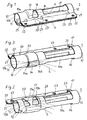
- FIG. 1 is a perspective view of a non-inventive gas flow distributor in the form of a generator carrier 1 for receiving a gas generator shown.
- the generator support 1 forms part of a side airbag module and can carry a gas generator with which a gas bag can be inflated to protect a vehicle occupant in the event of a crash in a sensor-controlled manner.
- the gas bag and the gas generator are usually arranged in a module housing, which has a cover which opens when the gas bag is inflated, so that the gas bag can deploy in the direction of the vehicle occupant to be protected.
- the gas generator is connected via the generator support 1 either to a supporting part of the airbag module, e.g. the housing of the airbag module, or directly with a supporting part of the vehicle body, e.g. a door panel or a seat frame in the case of a side airbag, connected.
- a supporting part of the airbag module e.g. the housing of the airbag module
- a supporting part of the vehicle body e.g. a door panel or a seat frame in the case of a side airbag
- the receiving region 10 of the generator carrier 1 is tubular, in particular designed as a wood cylinder, so that a tubular gas generator arranged within the receiving region 10 is enclosed by the receiving region 10.
- the receiving area 10 forms a slotted cross section Ring, of which both sides of the slot located ends each radially projecting a plate 21 and 22, respectively.
- the wooden cylindrical receiving area 10 has two open top surfaces 11, 12 at its end faces, which allow the insertion of a gas generator in the receiving area 10 by widening of said slot, and two large recesses 16, 17 in its outer surface, reducing the weight of the generator carrier 1 serve.
- an outlet opening 18 is additionally provided in the lateral surface, which is partially covered by a survey 13 of the outside wall 10a of the receiving area forming lateral surface and which is above the outflow openings of the introduced into the generator support 1 gas generator with imported gas generator.
- the elevation 13 serves as a guide element, with which the direction of the emerging from the outlet opening 18 gas flow can be influenced.
- the receiving region 10 of the generator carrier 1 is preferably arranged together with the gas generator arranged therein within the gas bag of the airbag module to be inflated.
- the arrangement, shape and size of the outlet opening 18 of the receiving area 10, through which gas flowing from a gas generator can pass into the airbag to be inflated, as well as the elevation 13 determine the direction and speed at which the gas enters the airbag.
- the gas flow G flowing through the outlet opening 18 is conducted by means of the elevation 13 along the lateral surface of the receiving area 10, in particular in the axial direction.
- two further outlet openings 19a, 19b are provided in the jacket of the receiving area 10 and the above outlet opening 18 radially opposite on both sides of a survey 13, through which a gas flow G can escape along the surface of the outer wall 10a of the receiving area 10, in particular in the axial direction of the elongated generator carrier 1.
- the gas generator to be accommodated in the receiving area 10 of the generator carrier 1 can there be arranged in particular such that gas flowing from the outflow openings of this gas generator is directed against the inner wall 10b of the receiving area 10.
- the outflow openings of the gas generator are preferably located in the region of the section of the receiving area 10 of the gas generator carrier 1 provided with the outlet openings 18, 19a, 19b.
- the gas flowing from the gas generator into the interior of the generator carrier 1 is first reflected on the inner wall 10b of the receiving area 10 before it passes through the openings 18, 19a, 19b provided for this purpose of the receiving area 10 in the gas bag to be inflated.
- the gas stream before impinging on any heat-sensitive parts of the airbag such. B. the airbag cover or seams, slightly cooled and braked. The risk of damage to the airbag by hot gases can thereby be significantly reduced.
- the connecting portion 20 is formed as a flange and consists of two abutting, integrally formed on the receiving portion 10 plates 21, 22.
- the receiving portion 10 in cross-section a slotted ring, at both ends of which one of the plates 21, 22 is formed.
- stiffening elements 25 are additionally provided, via which the connecting region 20 is additionally connected to the receiving region 10.
- FIG. 3 shown generator carrier differs from that in the Figures 1 and 2 shown only in terms of the formation of two outlet openings, which are provided in the wall of the receiving area 10 sin. Moreover, the two embodiments agree, so that in this regard to the comments on FIG. 1 is referenced. Matching components of the generator carrier are provided in the two figures with identical reference numerals.
- two outlet openings 14a, 14b located next to the two large-area recesses 16, 17 are formed by the two open end faces of a channel 14, which is formed as a protrusion on the outer wall 10a of the receiving area 10.
- the exiting through the open end faces 14a, 14b Gases G initially flow parallel to the outer wall 10a of the receiving region 10, predominantly in the axial direction of the generator carrier 1, and then reach the gas bag to be inflated.
- the generator carrier 1 is installed in a vehicle such that its longitudinal axis extends substantially along the vertical vehicle axis.
- the gas stream emerging from the gas distributor in the form of a generator carrier is therefore directed upwards or downwards in a vertical direction through the respective outlet openings 14a, 14b, 18, 19a, 19b.
- FIGS. 4 and 5 is a further modification of the gas flow distributor of the Figures 1 and 2 represented, with the difference only in the formation of the outlet openings, through which gas from a gas generator in the gas flow distributor (generator support 1) flowed gas can continue to flow in a gas bag to be inflated.
- FIGS. 4 and 5 is in addition to the large recesses 16, 17 arranged in the receiving area 10 of the generator carrier 1, an outlet opening 15 which is partially closed by a cover in the form of tabs 150.
- the recess 15 extends with slot-shaped extensions along the lateral edges of the tabs 150, so that they are connected only in one end portion with the lateral surface of the tubular receiving portion 10.
- the cross-sectional area of the outlet opening 15 is increased, through which the gas leaked from the gas generator can flow into the gas bag to be inflated.
- the tabs 150 after bending outward guide elements that help to guide the gas flow G while flowing through the outlet opening 15 along the lateral surface of the tubular receiving portion 10 of the generator carrier 1.
- the tabs 150 in this state counteract a radial and tangential outflow of the gases, so that the gas flow G above all has a component in the axial direction of the tubular receiving region 10.
- the flow direction of the gas passing through the outlet opening 15 can be influenced.
- FIGS. 6 and 7 a first gas flow distributor according to the invention is shown in one embodiment.
- the gas flow distributor has a receptacle in the form of a baffle element 3, which encloses a tubular gas generator 6 in the region of the gas outflow openings 60 of the tubular gas generator 6.
- the baffle element 3 has the form of a clamp-shaped receptacle, which encloses the tube gas generator 6 largely contactless. Between the clamp-shaped baffle element 3 and the tube gas generator 6, a gas guide channel 100 is thereby formed for guiding the gas flow flowing out of the gas outlet openings 60 of the tube gas generator 6.
- the tubular gas generator 6 is received in a likewise clamp-shaped fastening device 7 and can be attached via this to a motor vehicle structure, not shown here.
- the tubular gas generator 6 is received in a cylindrical recess 73 of the clamp-shaped fastening element 7.
- the fastening element 7 has a cut-out region 72, so that the gas flowing out of the gas outlet openings 60 is not hindered by the loop-shaped fastening element 7 at its outflow.
- the fastening element 7 moreover has a fastening region 70, which via joining elements guided in bores 701, 40 in the form of rivets and / or screws 401 serves to connect the tubular gas generator 6 together with the baffle element 3 to a motor vehicle structure.
- an airbag can be introduced between the attachment region 70 and a clamping rail 4 in such a way that the gas-conducting device is enclosed by the airbag fabric.
- the airbag is tightened around the baffle element and sealed or firmly connected to the gas guiding device and / or a connection to the vehicle structure.
- the baffle element 3 likewise has a fastening section 30, into which fastening means 401, which are likewise riveted by bores 301, can be guided and lead to an attachment of the clamp-shaped baffle element 3 to the clamp-shaped fastening element 7.
- a crescent-shaped gas duct 100 is formed between the gas generator 1 and the clamp-shaped baffle element 3.
- the gas flowing out of the gas outflow openings 60 of the tubular gas generator 6 first of all impacts the clamped baffle element 3 and is then directed in the gas guide channel 100 in the direction of two opposing gas outflow regions 101, 102.
- the gas streams emerging from the two gas outlet regions 101, 102 emerge in mutually substantially opposite directions and along the tube axis R of the tubular gas generator.
- the gas guide channel 100 in this case has a flow cross section, which results from the outer diameter D2 of the clamp-shaped fastening element 7 and the inner diameter D3 of the clamp-shaped impact element 3.
- the gas-conducting device has a receptacle in the form of a impact element 5, which can be arranged on a gas generator 6.
- the embodiment shown here integrates that in the embodiment of FIGS. 8 and 9 separately executed impact element with a fastening element for the gas generator.
- the gas generator designed as a tubular gas generator 6 is enclosed and received by clamp-shaped regions 50 of the baffle element 5.
- the clamp-shaped areas 50 are located in a region of the tubular gas generator 6, in which no gas outflow openings are provided.
- a further loop-shaped area 51 of the baffle element 5 is provided which has a larger diameter D5 than the clamp regions 50 holding the tube gas generator 6.
- a gas duct 100 is formed, which opens into two opposite gas outlet regions 101, 102.
- both the two clamp-shaped areas 50, which hold the tube gas generator 6, and the gas flow conducting clamp-shaped area 51 are integrally formed from a single sheet, they have a common "back" on, which is opposite to a fastening region 52 for connecting the gas guiding device to a vehicle structure.
- the gas guide channel 100 therefore has a crescent-shaped cross-section which results from the eccentric position of the tubular gas generator 6.
- the baffle element 5 also has a bracket 53, which holds an opening of an airbag arranged in this region open, so that a gas flow can flow unhindered into the airbag.
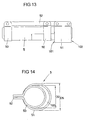
- FIGS. 12 to 14 a Gasleitvoroplasty invention is shown in a further embodiment, wherein the gas guide device in turn has a receptacle in the form of a baffle element 5, which can be arranged on a gas generator 6.
- the tube gas generator 6 is surrounded and received by clamp-shaped areas 50 of the baffle element 5.
- the baffle element 5 is configured here in such a way that the fastening region 52 lies on the side of the baffle element 5 opposite the gas guide channel 100.
- the Gasausströmö réelleen 101, 102 are in this way also on the mounting region opposite side of the gas guide.
- the individual clamp-shaped areas 50, 51 completely surround the gas generator 6.
- two gas bags are connected to the impact element 3, 5 in such a way that in each case at least one gas guide channel 100 opens into each gas bag.
- the baffle element 3, 5 can also be arranged in the region of a parting line between the two gas bags. By means of the gas guide channels formed by the baffle element, the two gas bags can be inflated so uniformly or in a predetermined manner with a single gas generator.
Landscapes
- Engineering & Computer Science (AREA)
- Mechanical Engineering (AREA)
- Physics & Mathematics (AREA)
- Fluid Mechanics (AREA)
- Air Bags (AREA)
Claims (15)
- Module d'airbag latéral comprenant un générateur de gaz tubulaire et un répartiteur de flux gazeux pour la répartition ciblée d'un flux gazeux sortant des orifices de sortie du générateur de gaz tubulaire dans une poche à gaz à gonfler par le générateur de gaz tubulaire, dans lequel- le répartiteur de flux gazeux est constitué d'un logement (1, 3, 5) de forme stable, enfermant le générateur de gaz tubulaire (6) au moins dans la zone des orifices de sortie, et le logement (1, 3, 5) présente des orifices de sortie (101, 102), à travers lesquels du gaz s'écoulant hors du générateur de gaz tubulaire (6) vers l'intérieur du logement (10) peut sortir et s'écouler dans la poche à gaz à gonfler,- le logement (1, 3, 5) est conçu comme élément déflecteur (3, 5) qui présente une section transversale sensiblement circulaire, dans lequel- au moins un canal de conduite de gaz (100) pour conduire le flux gazeux passe entre l'élément déflecteur (3, 5) et le générateur de gaz tubulaire (6), et- l'élément déflecteur (3, 5) est disposé de façon à ce que le flux gazeux (G) sortant du générateur de gaz tubilaire soit dévié sur l'élément déflecteur (3, 5) et réparti en deux flux gazeux qui débouchent dans le canal de conduite de gaz (100) en direction de deux orifices de sortie (101, 102) opposés l'un de l'autre sous la forme de zones de sortie de gaz (101, 102) du canal de conduite de gaz (100), dans lequel- les zones de sortie de gaz (101, 102) opposées l'une de l'autre du canal de conduite de gaz (100) sont les seules zones de sortie de gaz du canal de conduite de gaz (100), dans lequel l'axe du tube (R) du générateur de gaz tubulaire (G) et l'axe de section transversale de l'élément déflecteur sont distants l'un de l'autre, caractérisé en ce que l'élément déflecteur (3, 5) entoure le générateur de gaz tubulaire (G) seulement dans la zone des ouvertures de sortie du générateur de gaz tubulaire (G), et en ce que l'élément déflecteur (3, 5) est en forme de collier.
- Module d'airbag latéral selon la revendication 1, caractérisé en ce que le logement (1) se compose d'un matériau de forme stable de façon à ce qu'il ne soit pas déformé par le flux gazeux sortant du générateur de gaz tubulaire.
- Module d'airbag latéral selon la revendication 2, caractérisé en ce que logement (1) est composé en métal ou en fonte coulée sous pression.
- Module d'airbag latéral selon l'une quelconque des revendications précédentes, caractérisé en ce que le canal de conduite de gaz (100) passe essentiellement entre le côté extérieur du générateur de gaz tubulaire (6) et le côté intérieur de l'élément déflecteur (3, 5).
- Module d'airbag latéral selon l'une quelconque des revendications précédentes, caractérisé en ce que le canal de conduite de gaz (100) passe essentiellement entre le côté extérieur d'une zone du logement entourant le générateur de gaz tubulaire (6) et le côté intérieur de l'élément déflecteur (3, 5).
- Module d'airbag latéral selon l'une quelconque des revendications précédentes, caractérisé en ce que l'élément déflecteur (5, 51) est formé d'une seule pièce avec une autre zone du logement (50, 52).
- Module d'airbag latéral selon l'une quelconque des revendications précédentes, caractérisé en ce que le canal de conduite de gaz (100) comprend essentiellement une section transversale annulaire et/ou en forme de demi-lune.
- Module d'airbag latéral selon l'une quelconque des revendications précédentes, caractérisé en ce que les zones de sortie de gaz (101, 102) du canal de conduite de gaz (100) et/ou les orifices de sortie (14a, 14b, 15, 18, 19) du logement (1) débouchent dans au moins une poche à gaz.
- Module d'airbag latéral selon la revendication 8, caractérisé en ce que les zones de sortie de gaz (101, 102) du canal de conduite de gaz (100) et/ou les orifices de sortie (14a, 14b, 15, 18, 19) du logement (1) débouchent respectivement dans des chambres différentes de la poche à gaz et/ou dans des poches à gaz différentes.
- Module d'airbag latéral selon l'une quelconque des revendications précédentes, caractérisé en ce que l'élément déflecteur (3, 5) et/ou le logement (1) sert à séparer deux chambres de poches à gaz.
- Module d'airbag latéral selon l'une quelconque des revendications précédentes, caractérisé en ce qu'à l'élément déflecteur (3, 5) et/ou au logement (1) sont liées au moins deux poches à gaz et en ce que respectivement au moins un canal de conduite de gaz (100) et/ou au moins un orifice de sortie (14a, 14b, 15, 18, 19) débouche dans respectivement une poche à gaz.
- Module d'airbag latéral selon la revendication 11, caractérisé en ce qu'un joint de séparation passant entre deux poches à gaz passe dans la zone de l'élément déflecteur (3, 5) et/ou du logement (1).
- Module d'airbag latéral selon la revendication 12, caractérisé en ce que le joint de séparation peut être détendu de manière étanche au gaz sur l'élément déflecteur (3, 5) et/ou le logement (1).
- Module d'airbag latéral selon l'une quelconque des revendications précédentes, caractérisé en ce que la fonction de l'élément déflecteur (3, 5) et/ou du logement (1) reste maintenue lors d'une déformation plastique comme elle peut se produire lors du processus d'installation ou lors du fonctionnement du générateur de gaz tubulaire.
- Module d'airbag latéral selon l'une quelconque des revendications précédentes avec une poche à gaz pouvant être gonflée par le générateur de gaz, la zone de logement (10) du répartiteur de gaz (1) étant disposée à l'intérieur de la poche à gaz.
Applications Claiming Priority (4)
| Application Number | Priority Date | Filing Date | Title |
|---|---|---|---|
| DE20200365U DE20200365U1 (de) | 2002-01-04 | 2002-01-04 | Gasstromverteiler für ein Seitenairbagmodul |
| DE20217892U DE20217892U1 (de) | 2002-01-04 | 2002-11-15 | Gasleitvorrichtung für ein Seitenairbagmodul |
| EP05090236A EP1604872A1 (fr) | 2002-01-04 | 2002-12-23 | Repartiteur de flux gazeux pour module d'airbag latéral |
| EP02799038A EP1463652B2 (fr) | 2002-01-04 | 2002-12-23 | Repartiteur de flux gazeux pour module d'airbag lateral |
Related Parent Applications (3)
| Application Number | Title | Priority Date | Filing Date |
|---|---|---|---|
| EP02799038.1 Division | 2002-12-23 | ||
| EP05090236A Division EP1604872A1 (fr) | 2002-01-04 | 2002-12-23 | Repartiteur de flux gazeux pour module d'airbag latéral |
| EP05090236.0 Division | 2005-08-17 |
Publications (3)
| Publication Number | Publication Date |
|---|---|
| EP1925509A2 EP1925509A2 (fr) | 2008-05-28 |
| EP1925509A3 EP1925509A3 (fr) | 2008-10-01 |
| EP1925509B1 true EP1925509B1 (fr) | 2012-12-19 |
Family
ID=7966457
Family Applications (2)
| Application Number | Title | Priority Date | Filing Date |
|---|---|---|---|
| EP05090236A Ceased EP1604872A1 (fr) | 2002-01-04 | 2002-12-23 | Repartiteur de flux gazeux pour module d'airbag latéral |
| EP07075907A Expired - Lifetime EP1925509B1 (fr) | 2002-01-04 | 2002-12-23 | Distributeur de courant gazeux pour un module d'airbag latéral |
Family Applications Before (1)
| Application Number | Title | Priority Date | Filing Date |
|---|---|---|---|
| EP05090236A Ceased EP1604872A1 (fr) | 2002-01-04 | 2002-12-23 | Repartiteur de flux gazeux pour module d'airbag latéral |
Country Status (2)
| Country | Link |
|---|---|
| EP (2) | EP1604872A1 (fr) |
| DE (2) | DE20200365U1 (fr) |
Families Citing this family (6)
| Publication number | Priority date | Publication date | Assignee | Title |
|---|---|---|---|---|
| DE20200365U1 (de) * | 2002-01-04 | 2002-07-25 | Takata Petri Gmbh Ulm | Gasstromverteiler für ein Seitenairbagmodul |
| JP3922073B2 (ja) * | 2002-04-02 | 2007-05-30 | タカタ株式会社 | 外面展開型エアバッグ装置 |
| US7384062B2 (en) † | 2004-01-28 | 2008-06-10 | Nihon Plast Co., Ltd. | Airbag system |
| DE102004006318B4 (de) * | 2004-02-10 | 2010-06-02 | Autoliv Development Ab | Gasgeneratoreinheit für ein Gassack-Modul |
| DE202004012303U1 (de) * | 2004-08-05 | 2004-12-09 | Trw Automotive Safety Systems Gmbh | Gassackmodul für eine Fahrzeuginsassen-Rückhaltevorrichtung |
| DE202005019013U1 (de) | 2005-12-01 | 2006-04-20 | Takata-Petri (Ulm) Gmbh | Gasstromverteiler für ein Gassackmodul |
Citations (4)
| Publication number | Priority date | Publication date | Assignee | Title |
|---|---|---|---|---|
| DE1046552B (de) * | 1956-10-20 | 1958-12-18 | Ver Leichtmetallwerke Gmbh | Rohling fuer das einseitige Plattieren von Profilstangen durch Strangpressen |
| EP0790154A1 (fr) * | 1996-02-15 | 1997-08-20 | Trw Vehicle Safety Systems Inc. | Module de sac gonflable pour choc latéral |
| DE29921743U1 (de) * | 1999-12-10 | 2000-04-13 | Trw Repa Gmbh | Fahrzeuginsassen-Rückhaltesystem |
| DE19850448A1 (de) * | 1998-11-02 | 2000-05-04 | Takata Europ Gmbh | Airbag-Anordnung |
Family Cites Families (10)
| Publication number | Priority date | Publication date | Assignee | Title |
|---|---|---|---|---|
| US5340147A (en) * | 1991-12-19 | 1994-08-23 | Alliedsignal Inc. | Air bag inflator assembly |
| DE9408908U1 (de) | 1994-05-31 | 1994-11-17 | Trw Repa Gmbh | Gassack-Schutzvorrichtung |
| US5540460A (en) | 1995-04-26 | 1996-07-30 | Trw Vehicle Safety Systems Inc. | Air bag module |
| DE19626463B4 (de) | 1996-06-21 | 2005-07-07 | Takata-Petri Ag | Vorrichtung zur Beeinflussung des Einströmens des Gases in einen Gassack eines Airbagmoduls |
| DE19648137C2 (de) | 1996-11-21 | 2001-10-18 | Opel Adam Ag | Airbagmodul |
| WO1999042340A1 (fr) * | 1998-02-19 | 1999-08-26 | Breed Automotive Technology, Inc. | Dispositifs de regulation du systeme de sortie de gaz pour les systemes de gonflage des coussins gonflables |
| US6293581B1 (en) * | 1999-04-15 | 2001-09-25 | Honda Giken Kogyo Kabushiki Kaisha | Occupant restraint device |
| WO2000069690A1 (fr) * | 1999-05-17 | 2000-11-23 | Autoliv Asp, Inc. | Ensemble de gonflage pour impact lateral a refroidissement externe de gaz |
| DE10021845B4 (de) * | 2000-05-05 | 2017-07-27 | Volkswagen Ag | Dualairbagsystem als Rückhaltemittel bei einem Frontalaufprall |
| DE20200365U1 (de) * | 2002-01-04 | 2002-07-25 | Takata Petri Gmbh Ulm | Gasstromverteiler für ein Seitenairbagmodul |
-
2002
- 2002-01-04 DE DE20200365U patent/DE20200365U1/de not_active Expired - Lifetime
- 2002-11-15 DE DE20217892U patent/DE20217892U1/de not_active Expired - Lifetime
- 2002-12-23 EP EP05090236A patent/EP1604872A1/fr not_active Ceased
- 2002-12-23 EP EP07075907A patent/EP1925509B1/fr not_active Expired - Lifetime
Patent Citations (4)
| Publication number | Priority date | Publication date | Assignee | Title |
|---|---|---|---|---|
| DE1046552B (de) * | 1956-10-20 | 1958-12-18 | Ver Leichtmetallwerke Gmbh | Rohling fuer das einseitige Plattieren von Profilstangen durch Strangpressen |
| EP0790154A1 (fr) * | 1996-02-15 | 1997-08-20 | Trw Vehicle Safety Systems Inc. | Module de sac gonflable pour choc latéral |
| DE19850448A1 (de) * | 1998-11-02 | 2000-05-04 | Takata Europ Gmbh | Airbag-Anordnung |
| DE29921743U1 (de) * | 1999-12-10 | 2000-04-13 | Trw Repa Gmbh | Fahrzeuginsassen-Rückhaltesystem |
Also Published As
| Publication number | Publication date |
|---|---|
| EP1925509A2 (fr) | 2008-05-28 |
| EP1925509A3 (fr) | 2008-10-01 |
| EP1604872A1 (fr) | 2005-12-14 |
| DE20217892U1 (de) | 2003-02-13 |
| DE20200365U1 (de) | 2002-07-25 |
Similar Documents
| Publication | Publication Date | Title |
|---|---|---|
| EP1463652B2 (fr) | Repartiteur de flux gazeux pour module d'airbag lateral | |
| EP0685364B1 (fr) | Dispositif de protection à sac gonflable | |
| DE69300496T2 (de) | Reaktionsdose mit kreisförmigem Diffusor. | |
| EP1048531B1 (fr) | Dispositif de protection contre le choc latéral pour les occupants d'un véhicule | |
| DE60202329T2 (de) | Airbag-Vorrichtung mit variablen Belüftungsauslässen | |
| DE69316727T2 (de) | Diffusorvorrichtung und deren Einbau in ein aufblasbares Rückhaltesystem | |
| DE29517372U1 (de) | Gassack-Seitenaufprall-Schutzeinrichtung | |
| EP0769428A2 (fr) | Dispositif de protection à sac gonflable contre des chocs latéraux | |
| DE19749914A1 (de) | Vorrichtung für einen Aufprallschutz am Lenkrad eines Kraftfahrzeugs | |
| DE19927024A1 (de) | Airbagmodul für Lenkräder | |
| DE19616858C2 (de) | Seitenairbagmodul | |
| EP1625982B1 (fr) | Module d'airbag pour passager | |
| EP1925509A2 (fr) | Distributeur de courant gazeux pour un module d'airbag latéral | |
| EP0820908B1 (fr) | Module à coussin gonflable pour un système de retenue d'un passager de véhicule | |
| DE29812800U1 (de) | Gassackmodul für ein Fahrzeuginsassen-Rückhaltesystem | |
| EP1533198A1 (fr) | Module de coussin gonflable | |
| EP1501706B1 (fr) | Module sac gonflable d'un vehicule automobile | |
| EP2195204A1 (fr) | Dispositif de gonflement d'un module sac gonflable | |
| DE19909426B4 (de) | Airbageinheit | |
| WO2020070090A1 (fr) | Module de sac gonflable et procédé de montage d'un générateur de gaz dans un sac gonflable | |
| EP1890915B1 (fr) | Module de coussin gonflable de securite | |
| DE202007008161U1 (de) | Airbaganordnung für ein Kraftfahrzeug | |
| EP1827919A1 (fr) | Module d'airbag, en particulier destine a la zone du passager ou a la zone du genou | |
| DE29620298U1 (de) | Gassack-Modul | |
| DE19947262A1 (de) | Beifahrer-Airbagmodul für Kraftfahrzeuge |
Legal Events
| Date | Code | Title | Description |
|---|---|---|---|
| PUAI | Public reference made under article 153(3) epc to a published international application that has entered the european phase |
Free format text: ORIGINAL CODE: 0009012 |
|
| AC | Divisional application: reference to earlier application |
Ref document number: 1463652 Country of ref document: EP Kind code of ref document: P Ref document number: 1604872 Country of ref document: EP Kind code of ref document: P |
|
| AK | Designated contracting states |
Kind code of ref document: A2 Designated state(s): DE FR GB SE |
|
| PUAL | Search report despatched |
Free format text: ORIGINAL CODE: 0009013 |
|
| AK | Designated contracting states |
Kind code of ref document: A3 Designated state(s): DE FR GB SE |
|
| RIC1 | Information provided on ipc code assigned before grant |
Ipc: B60R 21/231 20060101ALI20080827BHEP Ipc: B60R 21/217 20060101ALI20080827BHEP Ipc: B60R 21/20 20060101AFI20080424BHEP Ipc: B60R 21/26 20060101ALI20080827BHEP |
|
| 17P | Request for examination filed |
Effective date: 20090331 |
|
| 17Q | First examination report despatched |
Effective date: 20090511 |
|
| AKX | Designation fees paid |
Designated state(s): DE FR |
|
| RAP1 | Party data changed (applicant data changed or rights of an application transferred) |
Owner name: TAKATA AG |
|
| GRAP | Despatch of communication of intention to grant a patent |
Free format text: ORIGINAL CODE: EPIDOSNIGR1 |
|
| RIN1 | Information on inventor provided before grant (corrected) |
Inventor name: SENDELBACH, HANS-PETER Inventor name: WEYRICH, CHIRSTIAN Inventor name: HEUSCHMID, RAINER Inventor name: AULBACH, ALEXANDER Inventor name: SIEGEL, WOLFGANG |
|
| GRAS | Grant fee paid |
Free format text: ORIGINAL CODE: EPIDOSNIGR3 |
|
| GRAA | (expected) grant |
Free format text: ORIGINAL CODE: 0009210 |
|
| AC | Divisional application: reference to earlier application |
Ref document number: 1604872 Country of ref document: EP Kind code of ref document: P Ref document number: 1463652 Country of ref document: EP Kind code of ref document: P |
|
| AK | Designated contracting states |
Kind code of ref document: B1 Designated state(s): DE FR |
|
| REG | Reference to a national code |
Ref country code: DE Ref legal event code: R096 Ref document number: 50215672 Country of ref document: DE Effective date: 20130207 |
|
| PLBE | No opposition filed within time limit |
Free format text: ORIGINAL CODE: 0009261 |
|
| STAA | Information on the status of an ep patent application or granted ep patent |
Free format text: STATUS: NO OPPOSITION FILED WITHIN TIME LIMIT |
|
| 26N | No opposition filed |
Effective date: 20130920 |
|
| REG | Reference to a national code |
Ref country code: DE Ref legal event code: R097 Ref document number: 50215672 Country of ref document: DE Effective date: 20130920 |
|
| REG | Reference to a national code |
Ref country code: FR Ref legal event code: PLFP Year of fee payment: 14 |
|
| PGFP | Annual fee paid to national office [announced via postgrant information from national office to epo] |
Ref country code: FR Payment date: 20151110 Year of fee payment: 14 |
|
| REG | Reference to a national code |
Ref country code: FR Ref legal event code: ST Effective date: 20170831 |
|
| PG25 | Lapsed in a contracting state [announced via postgrant information from national office to epo] |
Ref country code: FR Free format text: LAPSE BECAUSE OF NON-PAYMENT OF DUE FEES Effective date: 20170102 |
|
| REG | Reference to a national code |
Ref country code: DE Ref legal event code: R082 Ref document number: 50215672 Country of ref document: DE Representative=s name: MAIKOWSKI & NINNEMANN PATENTANWAELTE PARTNERSC, DE Ref country code: DE Ref legal event code: R081 Ref document number: 50215672 Country of ref document: DE Owner name: JOYSON SAFETY SYSTEMS GERMANY GMBH, DE Free format text: FORMER OWNER: TAKATA AG, 63743 ASCHAFFENBURG, DE |
|
| PGFP | Annual fee paid to national office [announced via postgrant information from national office to epo] |
Ref country code: DE Payment date: 20200227 Year of fee payment: 18 |
|
| REG | Reference to a national code |
Ref country code: DE Ref legal event code: R119 Ref document number: 50215672 Country of ref document: DE |
|
| PG25 | Lapsed in a contracting state [announced via postgrant information from national office to epo] |
Ref country code: DE Free format text: LAPSE BECAUSE OF NON-PAYMENT OF DUE FEES Effective date: 20210701 |