EP1925554A1 - Banding machine and method for banding pallets - Google Patents
Banding machine and method for banding pallets Download PDFInfo
- Publication number
- EP1925554A1 EP1925554A1 EP07020959A EP07020959A EP1925554A1 EP 1925554 A1 EP1925554 A1 EP 1925554A1 EP 07020959 A EP07020959 A EP 07020959A EP 07020959 A EP07020959 A EP 07020959A EP 1925554 A1 EP1925554 A1 EP 1925554A1
- Authority
- EP
- European Patent Office
- Prior art keywords
- pallet
- winding
- banding
- winding head
- holder
- Prior art date
- Legal status (The legal status is an assumption and is not a legal conclusion. Google has not performed a legal analysis and makes no representation as to the accuracy of the status listed.)
- Withdrawn
Links
- 238000000034 method Methods 0.000 title claims abstract description 9
- 238000004804 winding Methods 0.000 claims abstract description 43
- 239000000463 material Substances 0.000 claims abstract description 17
- 230000004888 barrier function Effects 0.000 claims abstract description 6
- 239000000047 product Substances 0.000 claims description 20
- 239000003292 glue Substances 0.000 claims description 9
- 239000006228 supernatant Substances 0.000 claims description 3
- 239000000853 adhesive Substances 0.000 claims 1
- 238000005096 rolling process Methods 0.000 description 2
- 241001136792 Alle Species 0.000 description 1
- 238000005516 engineering process Methods 0.000 description 1
- 230000003203 everyday effect Effects 0.000 description 1
- 235000013312 flour Nutrition 0.000 description 1
- 239000011888 foil Substances 0.000 description 1
- 235000013305 food Nutrition 0.000 description 1
- 239000000123 paper Substances 0.000 description 1
- 230000001681 protective effect Effects 0.000 description 1
- 238000004080 punching Methods 0.000 description 1
- 239000007921 spray Substances 0.000 description 1
- 229920006302 stretch film Polymers 0.000 description 1
- 230000001360 synchronised effect Effects 0.000 description 1
Images


Classifications
-
- B—PERFORMING OPERATIONS; TRANSPORTING
- B65—CONVEYING; PACKING; STORING; HANDLING THIN OR FILAMENTARY MATERIAL
- B65B—MACHINES, APPARATUS OR DEVICES FOR, OR METHODS OF, PACKAGING ARTICLES OR MATERIALS; UNPACKING
- B65B11/00—Wrapping, e.g. partially or wholly enclosing, articles or quantities of material, in strips, sheets or blanks, of flexible material
- B65B11/02—Wrapping articles or quantities of material, without changing their position during the wrapping operation, e.g. in moulds with hinged folders
- B65B11/025—Wrapping articles or quantities of material, without changing their position during the wrapping operation, e.g. in moulds with hinged folders by webs revolving around stationary articles
-
- B—PERFORMING OPERATIONS; TRANSPORTING
- B65—CONVEYING; PACKING; STORING; HANDLING THIN OR FILAMENTARY MATERIAL
- B65B—MACHINES, APPARATUS OR DEVICES FOR, OR METHODS OF, PACKAGING ARTICLES OR MATERIALS; UNPACKING
- B65B51/00—Devices for, or methods of, sealing or securing package folds or closures; Devices for gathering or twisting wrappers, or necks of bags
- B65B51/02—Applying adhesives or sealing liquids
-
- B—PERFORMING OPERATIONS; TRANSPORTING
- B65—CONVEYING; PACKING; STORING; HANDLING THIN OR FILAMENTARY MATERIAL
- B65B—MACHINES, APPARATUS OR DEVICES FOR, OR METHODS OF, PACKAGING ARTICLES OR MATERIALS; UNPACKING
- B65B2210/00—Specific aspects of the packaging machine
- B65B2210/14—Details of wrapping machines with web dispensers for application of a continuous web in layers onto the articles
- B65B2210/20—Details of wrapping machines with web dispensers for application of a continuous web in layers onto the articles the web dispenser being mounted on a rotary arm
Definitions
- the present invention relates to a banding machine for wrapping stacked product units on pallets with a strip material.
- the sales pallet is the dispatch pallet, as Euro pallet or as half Europallet.
- the units are loaded directly onto the pallet at the manufacturer without a shipping box. These are usually low-value everyday products, but they are part of the standard range and are sold in large quantities, eg. As toilet paper, kitchen rolls, 1 kg flour or sugar packs, etc.
- the pallet For shipping, the pallet is packed with a stretch film. In the showroom, the film is removed and the products are now loose on the pallet. For food, additional protection is required for the lower area, which is still present even after removal of the pallet foil. So far, this protection usually consisted of a box, in the base area as large as the pallet, in height one or two product layers high.
- this protection usually consisted of a box, in the base area as large as the pallet, in height one or two product layers high.
- the same carton was provided with a central perforation, in the palletizer two half pallets were placed side by side (the base area then corresponds to a Euro pallet) and the products loaded onto the perforated carton. The finished double half pallet was pulled apart on the following conveyor technology and the carton was divided. The half pallet was then secured only on three sides.
- the object of the present invention is therefore to provide an automatic banding machine with the aid of which the pallets mentioned above can be strapped automatically, in particular with corrugated cardboard as strip material, with very high processing speeds being achieved.
- the banding machine according to the invention is a separate station and solves these tasks outside of the palletizer.
- the palletizer does not have to be equipped with a power-reducing station, existing palletizers do not have to be rebuilt.
- Each pallet is individually strapped with a corrugated cardboard band at the desired height and glued automatically. Due to the high performance, the pallets can be brought from several palletizers to a banding machine.
- the operation of the device according to the invention is the following.
- the loaded pallet enters the banding machine on the pallet conveyor.
- a photocell detects the front edge of the load.
- the length of the pallet is measured by means of a light barrier.
- Corresponding the length is deducted in the winding station, the appropriate Banderolenwinin from the unwinding.
- the winding station is suspended in a 2-axis gantry system (portal robot).
- the winding station moves with the rolled-up banderole supply to the pallet and creates the beginning of the banderole on the front.
- the banderole holder pivots in and holds the beginning against the pallet load.
- the gantry robot moves the winding station around the pallet in a rectangle and places the banderole around the pallet load.
- the winding station is equipped with a controlled servomotor, the regulation being adjusted so that the band is always kept under tension during the unwinding process.
- the winding station When the winding station has reached the last pallet side, the winding station is pressed against the beginning of the band, holding it firmly.
- the banderole holder pivots back and the banderole can be wrapped around the edge of the pallet.
- the Banderolenende is held by the winding station away from the pallet, an intermediate Leimdüse sprays glue on the lower banderole, the pallet conveyor moves to and the standing banderole end is pressed with a subsequent side guide to the glued lower banderole and fixed.
- the corrugated cardboard roll is, roll axis horizontal, in the unwinding and is fed to the winding station with feed rollers.
- a punching knife separates the banderole.
- the reserve roll is inserted by hand into the unwinding, glued by hand to the end and the rolling process started with manual signal.
- the winding station consists of the winding station, a clamp for holding the Banderolenterrorisms, a pressure roller for holding the Banderolenendes and a rotary actuator.
- the axis of the winding station is horizontal. Then the axis is pivoted 90 degrees and is vertical during strapping.
- the winding station further consists of two separately driven cylinder segments. Depending on the drive position, the segments form an open or closed bracket.
- the unwinding rollers bring the beginning of the corrugated cardboard into the open clamp, the clamp is closed, the synchronized drive of both segments winds the band of banderoles onto the rewinding station.
- the spring-loaded pressure roller lies on the circumference of the coil and fixes the end of the band.
- the length of the initially placed against the pallet and held by Banderolenhalter band end is chosen so that this protrudes beyond the holder so that it can be pressed by the winding station and the band holder can be pivoted back afterwards.
- the strip material is stiff enough so that it protrudes after cutting and pivoting of the winding station by 90 ° as a flag of this and can be taken from the band holder.
- the figures 1-4 show the structure of the device and the process of banding, ie the strapping of the product units.
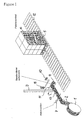
- Fig. 1 shows a conveyor 12 with a pallet 5, on which stacked product units 6 are located.
- a light barrier is arranged (not shown), which detects the length of the product stack at the inlet of the pallet.
- the strip material 2 is withdrawn for strapping and according to the required length, d. H.
- the winding head 4 is arranged at a winding station 11 1, which in turn is located on a support arm 3, which depends on a gantry robot (not shown).
- the winding station 11 is rotatably connected to the support arm 3. After the cutting of the strip material 2, the winding head 4 is brought into a vertical position, wherein the flag 13 protrudes as a projection of this. Furthermore, the pivotable banderole holder 8 and the glue application station 10 are shown.
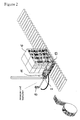
- FIG. 2 shows the stack of product units 6 delivered to the strapping position on the conveyor.
- the winding station 11 is suspended vertically from the support arm 3.
- the longitudinally standing flag 13 is gripped by the roll holder and placed against the product stack, the banderole holder initially remains in this position.
- the band end 9 stands over the banderole holder 8 with the flag 13 on. Thereafter, the gantry robot bypasses the pallet and wraps it with the strip material 2, as indicated in Fig. 3 .
- the glue application nozzles 10 apply glue to the lateral beginning of the strip and the winding station 11 is pressed against the lug 13. Thereafter, the banderole holder 8 is pivoted back and the portal robot pulls the band around the (in the illustration) rear side surface of the product stack 6 and glued the tape 2 to the beginning of the tape.
- Fig. 4 shows this situation. Subsequently, the glue nozzles move back. The pallet 5 is slowly moving out. In this case, the still fitting Banderolenhalter 8 presses the tape end 9 on the surface sprayed with glue. Thus, the band is connected at the ends. The banderole holder 8 moves to the basic position. The winding head 4 moves to receive the next banderole.
Landscapes
- Engineering & Computer Science (AREA)
- Mechanical Engineering (AREA)
- Basic Packing Technique (AREA)
Abstract
Description
Die vorliegende Erfindung betrifft einen Banderolierer zum Umwickeln von auf Paletten befindlichen gestapelten Produkteinheiten mit einem Bandmaterial.The present invention relates to a banding machine for wrapping stacked product units on pallets with a strip material.
Bei großen Supermärkten werden die Produkte nicht nur aus dem Regal, sondern auch von der so genannten Verkaufspalette ab verkauft. Die Verkaufspalette ist die Versandpalette, als Europalette oder als halbe Europalette.In large supermarkets, the products are sold not only from the shelf, but also from the so-called sales from. The sales pallet is the dispatch pallet, as Euro pallet or as half Europallet.
Die Einheiten werden beim Hersteller ohne Versandkarton direkt auf die Palette geladen. Meist handelt es sich um Produkte des täglichen Bedarfs mit geringerem Wert, die aber zum Standardsortiment gehören und in großen Mengen verkauft werden, z. B. Toilettenpapier, Küchenrollen, 1 kg Mehl- oder Zuckerpackungen usw.The units are loaded directly onto the pallet at the manufacturer without a shipping box. These are usually low-value everyday products, but they are part of the standard range and are sold in large quantities, eg. As toilet paper, kitchen rolls, 1 kg flour or sugar packs, etc.
Für den Versand wird die Palette mit einer Stretchfolie verpackt. Im Verkaufsraum wird die Folie abgenommen und die Produkte stehen jetzt lose auf der Palette. Bei Lebensmitteln wird ein zusätzlicher Schutz für den unteren Bereich verlangt, der auch nach Wegnahme der Palettenfolie noch vorhanden ist. Bisher bestand dieser Schutz meist aus einem Karton, in der Grundfläche so groß wie die Palette, in der Höhe ein bis zwei Produktlagen hoch. Bei der Euro-Halbpalette wurde der gleiche Karton mit einer mittigen Perforation versehen, im Palettierer wurden zwei Halbpaletten nebeneinander gesetzt (die Grundfläche entspricht dann einer Euro-Palette) und die Produkte auf den perforierten Karton geladen. Die fertige Doppel-Halbpalette wurde auf der nachfolgenden Fördertechnik auseinander gezogen und der Karton geteilt. Die Halbpalette war dann nur an drei Seiten gesichert.For shipping, the pallet is packed with a stretch film. In the showroom, the film is removed and the products are now loose on the pallet. For food, additional protection is required for the lower area, which is still present even after removal of the pallet foil. So far, this protection usually consisted of a box, in the base area as large as the pallet, in height one or two product layers high. In the Euro half pallet, the same carton was provided with a central perforation, in the palletizer two half pallets were placed side by side (the base area then corresponds to a Euro pallet) and the products loaded onto the perforated carton. The finished double half pallet was pulled apart on the following conveyor technology and the carton was divided. The half pallet was then secured only on three sides.
Inzwischen wird für den zusätzlichen Schutz mehr gefordert:
- Die Höhe des Schutzes soll mindestens 200 mm betragen,
- Es müssen immer alle vier Seiten geschützt werden.
- The height of the protection should be at least 200 mm,
- It is always necessary to protect all four sides.
Die bisherige Methode ist dafür nicht geeignet, die Höhe von 200 mm lässt sich im Lagenpalettierer nicht mehr realisieren, der allseitige Schutz bei der Halbpalette wäre nur durch eine Einzelpalettierung möglich, wegen der Leistungsminderung ist auch diese Lösung nicht brauchbar. Der notwendige Schutz wird deshalb nach dem Palettierer von Hand angebracht.The previous method is not suitable for this, the height of 200 mm can not be realized in the layer palletizer, the all-round protection in the half-pallet would be possible only by a Einzelpalettierung, because of the reduction in performance, this solution is not useful. The necessary protection is therefore applied after the palletizer by hand.
Die vorliegende Erfindung hat sich daher die Aufgabe gestellt, einen automatischen Banderolierer zu schaffen, mit dessen Hilfe die oben genannten Paletten automatisch, insbesondere mit Wellpappe als Bandmaterial, umreift werden können, wobei sehr hohe Verarbeitungsgeschwindigkeiten erzielt werden sollen.The object of the present invention is therefore to provide an automatic banding machine with the aid of which the pallets mentioned above can be strapped automatically, in particular with corrugated cardboard as strip material, with very high processing speeds being achieved.
Die Lösung dieser Aufgabe gelingt mit einem Banderolierer gemäß Hauptanspruch sowie einem Verfahren zum Banderolieren von Paletten gemäß Nebenanspruch. Vorteilhafte Ausgestaltungen finden sich in den Unteransprüchen.The solution to this problem is achieved with a banding according to the main claim and a method for banding pallets according to the independent claim. Advantageous embodiments can be found in the subclaims.
Die erfindungsgemäße Banderoliermaschine ist eine separate Station und löst diese Aufgaben außerhalb des Palettieres. Der Palettierer muss nicht mit einer leistungsmindernden Station ausgerüstet werden, vorhandene Palettierer müssen nicht umgebaut werden. Jede Palette wird einzeln mit einer Wellpappbanderole in gewünschter Höhe umreift und automatisch verklebt. Auf Grund der hohen Leistung können die Paletten von mehreren Palettierern zu einem Banderolierer gebracht werden.The banding machine according to the invention is a separate station and solves these tasks outside of the palletizer. The palletizer does not have to be equipped with a power-reducing station, existing palletizers do not have to be rebuilt. Each pallet is individually strapped with a corrugated cardboard band at the desired height and glued automatically. Due to the high performance, the pallets can be brought from several palletizers to a banding machine.
Die Arbeitsweise der erfindungsgemäßen Vorrichtung ist die folgende.The operation of the device according to the invention is the following.
Die beladene Palette fährt auf der Palettenfördertechnik in den Banderolierer ein. Mit einer Lichtschranke wird die Vorderkante der Beladung erfasst. Während des Einlaufes wird mittels Lichtschranke die Länge der Palette gemessen. Entsprechend der Länge wird in der Wickelstation die passende Banderolenlänge aus der Abrollung abgezogen. Die Wickelstation ist in einem 2-Achs-Portalsystem (Portalroboter) aufgehängt. Der Wickelstation fährt mit dem aufgerollten Banderolenvorrat an die Palette heran und legt den Banderolenanfang an der Vorderseite an. Der Banderolenhalter schwenkt ein und hält den Anfang gegen die Palettenladung fest. Der Portalroboter bewegt den Wickelstation im Rechteck um die Palette und legt die Banderole um die Palettenladung.The loaded pallet enters the banding machine on the pallet conveyor. A photocell detects the front edge of the load. During the run in, the length of the pallet is measured by means of a light barrier. Corresponding the length is deducted in the winding station, the appropriate Banderolenlänge from the unwinding. The winding station is suspended in a 2-axis gantry system (portal robot). The winding station moves with the rolled-up banderole supply to the pallet and creates the beginning of the banderole on the front. The banderole holder pivots in and holds the beginning against the pallet load. The gantry robot moves the winding station around the pallet in a rectangle and places the banderole around the pallet load.
Der Wickelstation ist mit einem geregelten Servomotor ausgerüstet, wobei die Regelung so eingestellt ist, dass die Banderole während des Abwickelvorgangs immer unter Spannung gehalten wird. Wenn der Wickelstation die letzte Palettenseite erreicht hat, wird der Wickelstation gegen den Banderolenanfang gedrückt, hält diesen fest. Der Banderolenhalter schwenkt zurück und die Banderole kann um die Palettenkante herumgelegt werden. Das Banderolenende wird vom Wickelstation von der Palette weg gehalten, eine dazwischen liegende Leimdüse sprüht Leim auf die untere Banderole, die Palettenfördertechnik fährt an und das weg stehende Banderolenende wird mit einer nachfolgenden Seitenführung an die beleimte untere Banderole angedrückt und fixiert.The winding station is equipped with a controlled servomotor, the regulation being adjusted so that the band is always kept under tension during the unwinding process. When the winding station has reached the last pallet side, the winding station is pressed against the beginning of the band, holding it firmly. The banderole holder pivots back and the banderole can be wrapped around the edge of the pallet. The Banderolenende is held by the winding station away from the pallet, an intermediate Leimdüse sprays glue on the lower banderole, the pallet conveyor moves to and the standing banderole end is pressed with a subsequent side guide to the glued lower banderole and fixed.
Die Wellpapprolle liegt, Rollenachse horizontal, in der Abrollung und wird mit Vorzugswalzen dem Wickelstation zugeführt. Ein Stanzmesser trennt die Banderole. Eine Lichtschranke in der Zuführung, außerhalb der Schutzgitter, erkennt das Ende der abgewickelten Wellpapperolle, der Abrollvorgang wird sofort gestoppt. Die Reserverolle wird von Hand in die Abrollung eingelegt, von Hand an das Ende angeklebt und der Abrollvorgang mit Hand-Signal gestartet.The corrugated cardboard roll is, roll axis horizontal, in the unwinding and is fed to the winding station with feed rollers. A punching knife separates the banderole. A photocell in the feeder, outside the protective grille, detects the end of the unwound corrugated cardboard roll, the rolling process is stopped immediately. The reserve roll is inserted by hand into the unwinding, glued by hand to the end and the rolling process started with manual signal.
Die Wickelstation besteht aus dem Wickelstation, einer Klammer für das Festhalten des Banderolenanfangs, einer Andrückrolle für das Festhalten des Banderolenendes und einem Schwenkantrieb.The winding station consists of the winding station, a clamp for holding the Banderolenanfangs, a pressure roller for holding the Banderolenendes and a rotary actuator.
Während des Aufwickelns des Banderolenvorrats auf den Wickelstation steht die Achse des Wickelstationes horizontal. Anschließend wird die Achse um 90 Grad geschwenkt und steht während der Umreifung senkrecht.During the winding of the banderole supply on the winding station, the axis of the winding station is horizontal. Then the axis is pivoted 90 degrees and is vertical during strapping.
Der Wickelstation besteht ferner aus zwei separat angetriebenen Zylindersegmenten. Je nach Antriebsstellung bilden die Segmente eine offene oder geschlossene Klammer. Die Vorzugswalzen der Abrollung bringen den Anfang der Wellpappe in die geöffnete Klammer, die Klammer wird geschlossen, der synchronisierte Antrieb beider Segmente wickelt den Banderolenvorrat auf den Wickelstation. Die gefederte Andrückrolle liegt auf dem Umfang des Wickels und fixiert das Ende der Banderole.The winding station further consists of two separately driven cylinder segments. Depending on the drive position, the segments form an open or closed bracket. The unwinding rollers bring the beginning of the corrugated cardboard into the open clamp, the clamp is closed, the synchronized drive of both segments winds the band of banderoles onto the rewinding station. The spring-loaded pressure roller lies on the circumference of the coil and fixes the end of the band.
Dabei wird die Länge des zunächst gegen die Palette gelegten und vom Banderolenhalter festgehaltenen Bandendes so gewählt, dass dieses über den Halter hinaussteht, damit es vom Wickelstation angedrückt und der Banderolenhalter danach zurück geschwenkt werden kann. Weiterhin ist das Bandmaterial steif genug, so dass es nach dem Ablängen und Schwenken des Wickelstationes um 90° als Fahne von diesem absteht und vom Banderolenhalter mitgenommen werden kann.In this case, the length of the initially placed against the pallet and held by Banderolenhalter band end is chosen so that this protrudes beyond the holder so that it can be pressed by the winding station and the band holder can be pivoted back afterwards. Furthermore, the strip material is stiff enough so that it protrudes after cutting and pivoting of the winding station by 90 ° as a flag of this and can be taken from the band holder.
Anhand der beiliegenden Figuren wird die vorliegende Erfindung näher erläutert.Reference to the accompanying figures , the present invention will be explained in more detail.
Dabei zeigen die Figuren 1 - 4 den Aufbau der Vorrichtung und den Ablauf des Banderolierens, d. h. das Umreifen der Produkteinheiten.The figures 1-4 show the structure of the device and the process of banding, ie the strapping of the product units.
Fig. 1 zeigt eine Fördereinrichtung 12 mit einer Palette 5, auf der sich aufgestapelte Produkteinheiten 6 befinden. Neben der Palette 5 ist eine Lichtschranke angeordnet (nicht gezeigt), die beim Einlauf der Palette die Länge des Produktstapels erfasst. Fig. 1 shows a
Von einer Vorratsrolle 1 wird das Bandmaterial 2 für die Umreifung abgezogen und entsprechend der benötigten Länge, d. h. dem Umfang des Produktstapels 6 sowie dem zusätzlich erforderlichen Überstand von einem Schneidwerkzeug 7 abgelängt und auf die Wickelstation 4 aufgewickelt, wobei dieser eine Klammer zugeordnet ist, die das aufgewickelte Bandmaterial sichert, wobei eine Fahne 13 in erforderlicher Länge übersteht.From a
Der Wickelkopf 4 ist an einer Wickelstation 11 1 angeordnet, der sich wiederum an einem Tragarm 3 befindet, der von einem Portalroboter (nicht gezeigt) abhängt.The winding
Die Wickelstation 11 ist drehbar mit dem Tragarm 3 verbunden. Nach dem Ablängen des Bandmaterials 2 wird der Wickelkopf 4 in eine senkrechte Position gebracht, wobei die Fahne 13 als Überstand von dieser absteht. Ferner sind der schwenkbare Banderolenhalter 8 und die Leimauftragsstation 10 dargestellt.The
Fig. 2 zeigt den in die Umreifungsposition auf der Fördereinrichtung zugestellten Stapel der Produkteinheiten 6. FIG. 2 shows the stack of
Der Wickelstation 11 hängt senkrecht vom Tragarm 3. Die in Längsrichtung stehende Fahne 13 wird vom Bandrollenhalter ergriffen und gegen den Produktstapel gelegt, wobei der Banderolenhalter zunächst in dieser Position verbleibt.The
Das Bandende 9 steht dabei über den Banderolenhalter 8 mit der Fahne 13 über. Danach umfährt der Portalroboter die Palette und umwickelt diese mit dem Bandmaterial 2, wie in Fig. 3 angedeutet. Die Leimauftragsdüsen 10 tragen auf den seitlichen Bandanfang Leim auf und die Wickelstation 11 wird gegen die Fahne 13 gedrückt. Danach wird der Banderolenhalter 8 zurück geschwenkt und der Portalroboter zieht die Banderole um die (in der Darstellung) rückwärtige Seitenfläche des Produktstapels 6 und verklebt das Band 2 mit dem Bandanfang.The band end 9 stands over the
Fig. 4 zeigt diese Situation.
Anschließend bewegen sich die Leimdüsen zurück. Die Palette 5 fährt langsam aus. Dabei drückt der noch anliegende Banderolenhalter 8 das Bandende 9 auf die mit Leim besprühte Fläche. Damit ist die Banderole an den Enden verbunden. Der Banderolenhalter 8 fährt in die Grundposition. Der Wickelkopf 4 fährt zur Aufnahme der nächsten Banderole. Fig. 4 shows this situation.
Subsequently, the glue nozzles move back. The pallet 5 is slowly moving out. In this case, the still fitting
- 11
- Vorratsrollesupply roll
- 22
- Bandmaterialband material
- 33
- TragarmBeam
- 44
- Wickelkopfwinding
- 55
- Palettepalette
- 66
- Produkteinheitenproduct units
- 77
- Schneidwerkzeugcutting tool
- 88th
- Banderolenhalterband holder
- 99
- Bandendetape end
- 1010
- Leimauftragsstationglue application
- 1111
- Wickelstationwinding station
- 1212
- FördereinrichtungConveyor
- 1313
- FahneBanner, flag
- 1414
- Endabschnittend
Claims (6)
Applications Claiming Priority (1)
| Application Number | Priority Date | Filing Date | Title |
|---|---|---|---|
| DE200610055991 DE102006055991A1 (en) | 2006-11-24 | 2006-11-24 | Banding machine and method for banding pallets |
Publications (1)
| Publication Number | Publication Date |
|---|---|
| EP1925554A1 true EP1925554A1 (en) | 2008-05-28 |
Family
ID=38969333
Family Applications (1)
| Application Number | Title | Priority Date | Filing Date |
|---|---|---|---|
| EP07020959A Withdrawn EP1925554A1 (en) | 2006-11-24 | 2007-10-26 | Banding machine and method for banding pallets |
Country Status (2)
| Country | Link |
|---|---|
| EP (1) | EP1925554A1 (en) |
| DE (1) | DE102006055991A1 (en) |
Families Citing this family (3)
| Publication number | Priority date | Publication date | Assignee | Title |
|---|---|---|---|---|
| IT201800005364A1 (en) * | 2018-05-14 | 2019-11-14 | MACHINE FOR MAKING A COMPOUND PALLETIZED LOAD | |
| EP4458690B1 (en) | 2023-05-05 | 2026-04-29 | Micha Augstein | Packaging device, packaging assembly and use |
| DE202023105575U1 (en) | 2023-05-05 | 2024-08-06 | Micha Augstein | Packaging equipment, packaging arrangement and use |
Citations (2)
| Publication number | Priority date | Publication date | Assignee | Title |
|---|---|---|---|---|
| GB1270051A (en) * | 1968-04-17 | 1972-04-12 | Reynolds Metals Co | Method of making a package |
| JPH09118386A (en) * | 1995-10-25 | 1997-05-06 | Sanyo Electric Co Ltd | Device for packing refrigerator and its packing method |
-
2006
- 2006-11-24 DE DE200610055991 patent/DE102006055991A1/en not_active Withdrawn
-
2007
- 2007-10-26 EP EP07020959A patent/EP1925554A1/en not_active Withdrawn
Patent Citations (2)
| Publication number | Priority date | Publication date | Assignee | Title |
|---|---|---|---|---|
| GB1270051A (en) * | 1968-04-17 | 1972-04-12 | Reynolds Metals Co | Method of making a package |
| JPH09118386A (en) * | 1995-10-25 | 1997-05-06 | Sanyo Electric Co Ltd | Device for packing refrigerator and its packing method |
Also Published As
| Publication number | Publication date |
|---|---|
| DE102006055991A1 (en) | 2008-05-29 |
Similar Documents
| Publication | Publication Date | Title |
|---|---|---|
| DE19549664C2 (en) | Device for packaging a roll of material web | |
| DE2451149C2 (en) | Device for rolling up and compressing a flexible, compressible strip | |
| DE2413807A1 (en) | METHOD AND DEVICE FOR MANUFACTURING PACKAGING BY MEANS OF A TAPE AROUND THE PACKAGED GOODS | |
| EP0156012B1 (en) | Method of enveloping stacked goods | |
| DE69309473T2 (en) | METHOD FOR PACKING LOADS BY STRETCH FILM, MACHINE AND FILM FOR EXERCISING THE METHOD | |
| DE102015012972A1 (en) | Tape applicator with clamping device | |
| DE2724100A1 (en) | PROCESS AND DEVICE FOR AUTOMATIC PACKAGING OF UNIT GOODS | |
| DE3641757C2 (en) | Method and device for producing self-adhesive note blocks | |
| DE69917627T2 (en) | Method and machine for packaging annular strands of a flexible elongate element | |
| EP0427126B1 (en) | Device for changing a band | |
| DE4016484C2 (en) | Packing device for web rolls | |
| WO1999042397A1 (en) | Method and device for inserting a plurality of individual sheetlike forms of administration in a dispenser by forming a multilayer pile | |
| DE10057597A1 (en) | Device for storing and unrolling of continuous material for use in book-binding machines etc., in which rolls are stored in a shaft lined with rollers, so that as a roll unwinds it is drawn forward leaving space for the next roll | |
| DE3825861C2 (en) | ||
| EP1749590A2 (en) | Process for applying adhesives on a band connection and adhesive tape applicator | |
| DE69312823T2 (en) | Automatic winding machine for band-like products | |
| DE102006055991A1 (en) | Banding machine and method for banding pallets | |
| DE102007008996A1 (en) | Product roll from tissue paper or non-woven material useful in kitchen and toilet, comprises a web of paper sheets connected together in rows by perforation lines and wrapped to the product roll, and adhesive pattern | |
| DE10139563B4 (en) | Apparatus and method for preparing a stock paper web roll for flying reel change | |
| EP4662130A1 (en) | Packaging machine and method for producing packaging units | |
| DE3710639C2 (en) | ||
| EP2082982B1 (en) | Coiling device | |
| WO2009111809A1 (en) | Method for rolling up a paper web | |
| DE19752112C1 (en) | Roll winding device | |
| DE102014113393A1 (en) | Method and device for producing packaging containers |
Legal Events
| Date | Code | Title | Description |
|---|---|---|---|
| PUAI | Public reference made under article 153(3) epc to a published international application that has entered the european phase |
Free format text: ORIGINAL CODE: 0009012 |
|
| AK | Designated contracting states |
Kind code of ref document: A1 Designated state(s): AT BE BG CH CY CZ DE DK EE ES FI FR GB GR HU IE IS IT LI LT LU LV MC MT NL PL PT RO SE SI SK TR |
|
| AX | Request for extension of the european patent |
Extension state: AL BA HR MK RS |
|
| 17P | Request for examination filed |
Effective date: 20081128 |
|
| AKX | Designation fees paid |
Designated state(s): AT BE BG CH CY CZ DE DK EE ES FI FR GB GR HU IE IS IT LI LT LU LV MC MT NL PL PT RO SE SI SK TR |
|
| GRAP | Despatch of communication of intention to grant a patent |
Free format text: ORIGINAL CODE: EPIDOSNIGR1 |
|
| STAA | Information on the status of an ep patent application or granted ep patent |
Free format text: STATUS: THE APPLICATION IS DEEMED TO BE WITHDRAWN |
|
| 18D | Application deemed to be withdrawn |
Effective date: 20090729 |