EP1925618A1 - Composés à base d'imidazopyridine et diode électroluminescente organique comprenant une couche organique comprenant les composés à base d'imidazopyridine - Google Patents
Composés à base d'imidazopyridine et diode électroluminescente organique comprenant une couche organique comprenant les composés à base d'imidazopyridine Download PDFInfo
- Publication number
- EP1925618A1 EP1925618A1 EP07120635A EP07120635A EP1925618A1 EP 1925618 A1 EP1925618 A1 EP 1925618A1 EP 07120635 A EP07120635 A EP 07120635A EP 07120635 A EP07120635 A EP 07120635A EP 1925618 A1 EP1925618 A1 EP 1925618A1
- Authority
- EP
- European Patent Office
- Prior art keywords
- groups
- unsubstituted
- substituted
- compound
- group
- Prior art date
- Legal status (The legal status is an assumption and is not a legal conclusion. Google has not performed a legal analysis and makes no representation as to the accuracy of the status listed.)
- Granted
Links
- 0 Cc1c(*)c2ccccc2c(*)c1C=C=IC Chemical compound Cc1c(*)c2ccccc2c(*)c1C=C=IC 0.000 description 2
- WSFRPDVLCGKOKJ-UHFFFAOYSA-N Brc(cc1)ccc1-c(nc1[n]2cccc1)c2I Chemical compound Brc(cc1)ccc1-c(nc1[n]2cccc1)c2I WSFRPDVLCGKOKJ-UHFFFAOYSA-N 0.000 description 1
- MIVKNYUGPASSPY-UHFFFAOYSA-N Brc(cc1)ccc1-c1c(-c2ccccc2)[n](cccc2)c2n1 Chemical compound Brc(cc1)ccc1-c1c(-c2ccccc2)[n](cccc2)c2n1 MIVKNYUGPASSPY-UHFFFAOYSA-N 0.000 description 1
- QVKHZQKLTQWPAU-UHFFFAOYSA-N C=[Br]c(cc1)ccc1-c1c[n](cccc2)c2n1 Chemical compound C=[Br]c(cc1)ccc1-c1c[n](cccc2)c2n1 QVKHZQKLTQWPAU-UHFFFAOYSA-N 0.000 description 1
- VTJWFNDXMBRAMS-UHFFFAOYSA-N Cc1c(C(CC2)=CC=C2c(cc2)cc3c2c(-c2ccccc2)c(cccc2)c2c3-c2ccccc2)nc2[n]1cccc2 Chemical compound Cc1c(C(CC2)=CC=C2c(cc2)cc3c2c(-c2ccccc2)c(cccc2)c2c3-c2ccccc2)nc2[n]1cccc2 VTJWFNDXMBRAMS-UHFFFAOYSA-N 0.000 description 1
Images
Classifications
-
- C—CHEMISTRY; METALLURGY
- C07—ORGANIC CHEMISTRY
- C07D—HETEROCYCLIC COMPOUNDS
- C07D471/00—Heterocyclic compounds containing nitrogen atoms as the only ring hetero atoms in the condensed system, at least one ring being a six-membered ring with one nitrogen atom, not provided for by groups C07D451/00 - C07D463/00
- C07D471/02—Heterocyclic compounds containing nitrogen atoms as the only ring hetero atoms in the condensed system, at least one ring being a six-membered ring with one nitrogen atom, not provided for by groups C07D451/00 - C07D463/00 in which the condensed system contains two hetero rings
- C07D471/04—Ortho-condensed systems
-
- C—CHEMISTRY; METALLURGY
- C07—ORGANIC CHEMISTRY
- C07D—HETEROCYCLIC COMPOUNDS
- C07D519/00—Heterocyclic compounds containing more than one system of two or more relevant hetero rings condensed among themselves or condensed with a common carbocyclic ring system not provided for in groups C07D453/00 or C07D455/00
-
- C—CHEMISTRY; METALLURGY
- C09—DYES; PAINTS; POLISHES; NATURAL RESINS; ADHESIVES; COMPOSITIONS NOT OTHERWISE PROVIDED FOR; APPLICATIONS OF MATERIALS NOT OTHERWISE PROVIDED FOR
- C09K—MATERIALS FOR MISCELLANEOUS APPLICATIONS, NOT PROVIDED FOR ELSEWHERE
- C09K11/00—Luminescent materials, e.g. electroluminescent or chemiluminescent
- C09K11/06—Luminescent materials, e.g. electroluminescent or chemiluminescent containing organic luminescent materials
-
- H—ELECTRICITY
- H05—ELECTRIC TECHNIQUES NOT OTHERWISE PROVIDED FOR
- H05B—ELECTRIC HEATING; ELECTRIC LIGHT SOURCES NOT OTHERWISE PROVIDED FOR; CIRCUIT ARRANGEMENTS FOR ELECTRIC LIGHT SOURCES, IN GENERAL
- H05B33/00—Electroluminescent light sources
- H05B33/12—Light sources with substantially two-dimensional [2D] radiating surfaces
- H05B33/14—Light sources with substantially two-dimensional [2D] radiating surfaces characterised by the chemical or physical composition or the arrangement of the electroluminescent material, or by the simultaneous addition of the electroluminescent material in or onto the light source
-
- C—CHEMISTRY; METALLURGY
- C09—DYES; PAINTS; POLISHES; NATURAL RESINS; ADHESIVES; COMPOSITIONS NOT OTHERWISE PROVIDED FOR; APPLICATIONS OF MATERIALS NOT OTHERWISE PROVIDED FOR
- C09K—MATERIALS FOR MISCELLANEOUS APPLICATIONS, NOT PROVIDED FOR ELSEWHERE
- C09K2211/00—Chemical nature of organic luminescent or tenebrescent compounds
- C09K2211/10—Non-macromolecular compounds
- C09K2211/1003—Carbocyclic compounds
- C09K2211/1007—Non-condensed systems
-
- C—CHEMISTRY; METALLURGY
- C09—DYES; PAINTS; POLISHES; NATURAL RESINS; ADHESIVES; COMPOSITIONS NOT OTHERWISE PROVIDED FOR; APPLICATIONS OF MATERIALS NOT OTHERWISE PROVIDED FOR
- C09K—MATERIALS FOR MISCELLANEOUS APPLICATIONS, NOT PROVIDED FOR ELSEWHERE
- C09K2211/00—Chemical nature of organic luminescent or tenebrescent compounds
- C09K2211/10—Non-macromolecular compounds
- C09K2211/1003—Carbocyclic compounds
- C09K2211/1011—Condensed systems
-
- H—ELECTRICITY
- H10—SEMICONDUCTOR DEVICES; ELECTRIC SOLID-STATE DEVICES NOT OTHERWISE PROVIDED FOR
- H10K—ORGANIC ELECTRIC SOLID-STATE DEVICES
- H10K50/00—Organic light-emitting devices
- H10K50/10—OLEDs or polymer light-emitting diodes [PLED]
- H10K50/11—OLEDs or polymer light-emitting diodes [PLED] characterised by the electroluminescent [EL] layers
-
- H—ELECTRICITY
- H10—SEMICONDUCTOR DEVICES; ELECTRIC SOLID-STATE DEVICES NOT OTHERWISE PROVIDED FOR
- H10K—ORGANIC ELECTRIC SOLID-STATE DEVICES
- H10K85/00—Organic materials used in the body or electrodes of devices covered by this subclass
- H10K85/60—Organic compounds having low molecular weight
- H10K85/615—Polycyclic condensed aromatic hydrocarbons, e.g. anthracene
- H10K85/626—Polycyclic condensed aromatic hydrocarbons, e.g. anthracene containing more than one polycyclic condensed aromatic rings, e.g. bis-anthracene
-
- H—ELECTRICITY
- H10—SEMICONDUCTOR DEVICES; ELECTRIC SOLID-STATE DEVICES NOT OTHERWISE PROVIDED FOR
- H10K—ORGANIC ELECTRIC SOLID-STATE DEVICES
- H10K85/00—Organic materials used in the body or electrodes of devices covered by this subclass
- H10K85/60—Organic compounds having low molecular weight
- H10K85/649—Aromatic compounds comprising a hetero atom
- H10K85/657—Polycyclic condensed heteroaromatic hydrocarbons
Definitions
- the invention refers to new imidazopyridine-based compounds of Formula 1 and their use in an organic layer, preferably as an electron transport layer of an organic light emitting diode (OLED). Furthermore the invention refers to an OLED comprising at least an imidazopyridine-based compound of Formula 1.
- the present invention relates to imidazopyridine-based compounds and to organic light emitting diodes including organic layers comprising the imidazopyridine-based compounds. More particularly, the invention is directed to imidazopyridine-based compounds suitable for electron transport layers of organic light emitting diodes and to organic light emitting diodes including organic layers comprising the imidazopyridine-based compounds.
- OLEDs Organic Light emitting diodes
- organic light emitting diodes have good luminance, operating voltage and response times, and can realize multicolor images.
- an anode is formed on a substrate, and a hole transport layer, an emissive layer, an electron transport layer and a cathode are sequentially formed on the anode.
- the hole transport layer, the emissive layer and the electron transport layer are organic thin films formed of organic compounds.
- An organic light emitting diode having such a structure operates as follows. When a voltage is applied to the anode and cathode, holes injected from the anode migrate to the emissive layer via the hole transport layer. The electrons injected from the cathode migrate to the emissive layer via the electron transport layer. The holes and the electrons recombine with each other in the emissive layer to generate excitons.
- Heteroaromatic compounds such as oxadiazoles, thiadiazoles, pyrimidines and the like may be used as the material for forming the electron transport layer.
- conventional organic light emitting diodes do not have satisfactory driving voltages, luminance, current densities, power efficiencies, life-times and the like.
- imidazopyridine-based compounds of Formula 1 which have high electron transport capabilities.
- an organic light emitting diode using such a imidazopyridine-based compound of Formula 1 has high efficiency, low driving voltage, high luminance and a long life-time.
- the new imidazopyridine-based compounds are represented by Formula 1 below.
- p and q are each independently selected from integers ranging from 1 to 5
- m and n are each independently selected from integers ranging from 0 to 4, and both m and n are not 0.
- R 1 , R 2 , R 3 , R 4 , R 5 , R 6 , R 7 , R 8 , R 9 , R 10 , R 11 and R 12 are each independently selected from hydrogen atoms, halogen atoms, hydroxyl groups, cyano groups, substituted or unsubstituted C 1 -C 30 alkyl groups, substituted or unsubstituted C 1 -C 30 alkoxy groups, substituted or unsubstituted C 1 -C 30 acyl groups, substituted or unsubstituted C 2 -C 30 alkenyl groups, substituted or unsubstituted C 2 -C 30 alkynyl groups, substituted or unsubstituted C 6 -C 30 aryl groups, and substituted or unsubstituted C 3 -C 30 heteroaryl groups.
- At least two of R 4 , R 5 , R 6 and R 7 are bound to each other to form a saturated or unsaturated ring. At least two of R 9 , R 10 , R 11 and R 12 are bound to each other to form a saturated or unsaturated ring.
- L 1 and L 2 may each be independently selected from single bonds, substituted or unsubstituted C 1 -C 30 alkylene groups, substituted or unsubstituted C 6 -C 30 arylene groups, and substituted or unsubstituted C 3 -C 30 heteroarylene groups.
- Ar 1 and Ar 2 may each be independently selected from substituted or unsubstituted C 6 -C 30 aryl groups, and substituted or unsubstituted C 3 -C 30 heteroaryl groups.
- x and y are independently of each other 0, 1, 2, 3 or 4.
- an organic light emitting diode comprises a first electrode, a second electrode, and an organic layer between the first second electrodes, the organic layer including a imidazopyridine-based compound of Formula 1.
- the imidazopyridine-based compounds represented by Formula 1 have high electron transporting abilities, enabling organic light emitting diodes including organic layers having an imidazopyridine-based compound to have low driving voltages, high current densities, high luminance, high efficiencies and long life-times.
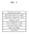
- FIG. 1 is a schematic illustrating an organic light emitting diode according to an embodiment of the present invention
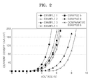
- FIG. 2 is a graph comparing voltage-current density properties of the organic light emitting diodes prepared according to Examples 2 through 6 and the organic light emitting diode prepared according to the Comparative Example;
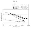
- FIG. 3 is a graph comparing luminance-efficiency properties of the organic light emitting diodes prepared according to Examples 2 through 6 and the organic light emitting diode prepared according to the Comparative Example.
- Subject-matter of the invention is an imidazopyridine-based compound according to an embodiment of the present invention which is represented by Formula 1 below.
- L 1 or L 2 bind an imidazopyridine ring to at least one of the 1 st through 8 th positions of an anthracene ring, but not to the 9 th or 10 th position of the ring.
- the imidazopyridine ring is not bound to the 9 th or 10 th position of the anthracene ring because the 9 th and 10 th positions are structurally weak points.
- the group can be easily decomposed from the anthracene ring by heat, oxygen, moisture or the like.
- an imidazopyridine ring which is electron deficient
- the imidazopyridine ring can be easily decomposed from the anthracene ring by heat generated during formation of the organic layer (for example, by deposition or the like) of an organic light emitting diode (OLED).
- the imidazopyridine ring can also be decomposed from the anthracene ring during operation of the organic light emitting diode, thus deteriorating the characteristics of the organic light emitting diode.
- an aromatic ring such as an aryl group or a heteroaryl group is bound to the 9 th or 10 th position of the anthracene ring.
- an imidazopyridine ring (which is electron deficient) is bound to at least one of the 1 st through 8 th positions of the anthracene ring, preferably over L 1 or L 2 . Accordingly, the imidazopyridine-based compound shows improved structural stability and electron mobility.
- R 1 , R 2 , R 3 , R 4 , R 5 , R 6 , R 7 , R 8 , R 9 , R 10 , R 11 and R 12 are each independently selected from hydrogen atoms, halogen atoms, hydroxyl groups, cyano groups, substituted or unsubstituted C 1 -C 30 alkyl groups, substituted or unsubstituted C 1 -C 3o alkoxy groups, substituted or unsubstituted C 1 -C 30 acyl groups, substituted or unsubstituted C 2 -C 30 alkenyl groups, substituted or unsubstituted C 2 -C 30 alkynyl groups, substituted or unsubstituted C 6 -C 30 aryl groups, and substituted or unsubstituted C 3 -C 30 heteroaryl groups.
- R 4 , R 5 , R 6 and R 7 may be bound to each other to form a saturated or unsaturated ring, and/or at least two of adjoining R 9 , R 10 , R 11 and R 12 may be bound to each other to form a saturated or unsaturated ring.
- x and y are independently of each other 0, 1,2,3 or 4.
- R 1 through R 12 may each be independently selected from hydrogen atoms, substituted or unsubstituted C 1 -C 10 alkyl groups, substituted or unsubstituted C 2 -C 10 alkenyl groups, substituted or unsubstituted C 6 -C 12 aryl groups, and substituted or unsubstituted C 3 -C 12 heteroaryl groups.
- At least two of R 4 , R 5 , R 6 and R 7 , or at least two of Rg, R 10 , R 11 and R 12 are bound to one another to form a substituted or unsubstituted C 6 -C 12 aromatic ring.
- L 1 and L 2 may each be independently selected from single bonds, substituted or unsubstituted C 1 -C 30 alkylene groups, substituted or unsubstituted C 6 -C 30 arylene groups, and substituted or unsubstituted C 3 -C 30 heteroarylene groups.
- L 1 and L 2 may each be independently selected from substituted or unsubstituted C 6 -C 12 arylene groups, and substituted or unsubstituted C 3 -C 12 heteroarylene groups.
- L 1 and/or L 2 are preferably a phenylene group.
- Ar 1 and Ar 2 may each be independently selected from substituted or unsubstituted C 6 -C 30 aryl groups, and substituted or unsubstituted C 3 -C 30 heteroaryl groups.
- Ar 1 and Ar 2 may each be independently selected from substituted or unsubstituted C 6 -C l2 aryl groups, and substituted or unsubstituted C 3 -C 12 heteroaryl groups.
- Ar 1 and Ar 2 are identical and selected from substituted or unsubstituted C 6 -C 12 aryl groups, especially preferable is an unsubstituted phenyl or naphthyl group.
- p and q are each independently selected from integers ranging from 1 to 5. In one embodiment, for example, p and q are each integers ranging from 1 to 3. That is, at least one imidazopyridine ring can be bound to L 1 or L 2 , which can be determined by the chemical structure of L 1 or L 2 .
- m and n are each independently selected from integers ranging from 0 to 4, but both m and n are not 0. That is, in an imidazopyridine-based compound according to one embodiment of the present invention, at least one of the 1 st through 8 th positions of the anthracene ring is bound to an imidazopyridine ring, preferably over L 1 and L 2 respectively.
- m and n can be 0 and 1.
- m may be 0, and n may be 1.
- both m and n may be 1.
- Nonlimiting examples of suitable unsubstituted C 1 -C 30 alkyl groups for use in the compounds represented by Formula 1 include methyl groups, ethyl groups, propyl groups, isobutyl groups, sec-butyl groups, pentyl groups, iso-amyl groups, hexyl groups, and the like.
- At least one hydrogen atom of the alkyl group may be substituted with a substituent selected from halogen atoms, hydroxyl groups, nitro groups, cyano groups, amino groups, amidino groups, hydrazine, hydrazone, carboxyl groups or salts thereof, sulfonic acid groups or salts thereof, phosphoric acid groups or salts thereof, C 1 -C 30 alkyl groups, C 1 -C 30 alkenyl groups, C 1 -C 30 alkynyl groups, C 6 -C 30 aryl groups, C 7 -C 20 arylalkyl groups, C 2 -C 20 heteroaryl groups and C 3 -C 30 heteroarylalkyl groups.
- a substituent selected from halogen atoms, hydroxyl groups, nitro groups, cyano groups, amino groups, amidino groups, hydrazine, hydrazone, carboxyl groups or salts thereof, sulfonic acid groups or salts thereof, phosphoric acid groups
- Nonlimiting examples of suitable unsubstituted C 1 -C 30 alkoxy groups for use in compounds represented by Formula 1 include methoxy groups, ethoxy groups, phenyloxy groups, cyclohexyloxy groups, naphthyloxy groups, isopropyloxy groups, diphenyloxy groups and the like. At least one hydrogen atom of the alkoxy group can be substituted with a substituent selected from those discussed above with respect to the C 1 -C 30 alkyl groups.
- Nonlimiting examples of suitable unsubstituted C 1 -C 30 acyl groups for use in compounds represented by Formula 1 include acetyl groups, ethylcarbonyl groups, isopropylcarbonyl groups, phenylcarbonyl groups, naphthylenecarbonyl groups, diphenylcarbonyl groups, cyclohexylcarbonyl groups, and the like. At least one hydrogen atom of the C 1 -C 30 acyl group can be substituted with a substituent selected from those discussed above with respect to the C 1 -C 30 alkyl groups.
- Nonlimiting examples of suitable unsubstituted C 2 -C 30 alkenyl groups for use in the compounds represented by Formula 1 include compounds containing a carbon-carbon double bond in the middle or end of an alkyl group defined above.
- the unsubstituted C 2 -C 30 alkenyl group may be selected from ethylene groups, propylene groups, butylene groups, hexylene groups, and the like.
- At least one hydrogen atom of the alkenyl group can be substituted with a substituent selected from those discussed above with respect to the C 1 -C 30 alkyl groups.
- Nonlimiting examples of suitable unsubstituted C 2 -C 30 alkynyl groups for use in compounds represented by Formula 1 include compounds containing a carbon-carbon triple bond in the middle or end of an alkyl group defined above.
- the unsubstituted C 2 -C 30 alkynyl group may be selected from acetylene groups, propylene groups, phenylacetylene groups, naphthylacetylene groups, isopropylacetylene groups, t-butylacetylene groups, diphenylacetylene groups, and the like.
- At least one hydrogen atom of the alkynyl group can be substituted with a substituent selected from those discussed above with respect to the C 1 -C 30 alkyl groups.
- Nonlimiting examples of suitable unsubstituted C 6 -C 30 aryl groups for use in compounds represented by Formula 1 include C 6 -C 30 carbocyclic aromatic systems containing at least one aromatic ring.
- the at least one aromatic ring can include at least two rings fused with each other, or bound to each other by a single bond, or the like.
- At least one hydrogen atom of the aryl group can be substituted with a substituent selected from those discussed above with respect to the C 1 -C 30 alkyl groups.
- the substituted or unsubstituted C 6 -C 30 aryl group can be selected from phenyl groups, C 1 -C 10 alkylphenyl groups (for example, an ethylphenyl group), C 1 -C 10 alkylbiphenyl groups (for example, an ethylbiphenyl group), halophenyl groups (for example, o-, m- and p-fluorophenyl groups, and dichlorophenyl groups), dicyanophenyl groups, trifluoro methoxy phenyl groups, o-, m-, and p-tolyl groups, o-, m- and p-cumenyl groups, mesityl groups, phenoxy phenyl groups, ( ⁇ , ⁇ -dimethylbenzyl)phenyl groups, (N,N'-dimethyl)aminophenyl groups, (N,N'-diphenyl)aminophenyl groups, pen
- Nonlimiting examples of suitable unsubstituted C 3 -C 30 heteroaryl groups for use in compounds represented by Formula 1 include systems having at least one aromatic ring that includes at least one hetero atom selected from N, O, P and S, where the remaining ring member is carbon.
- the at least one aromatic ring can be at least two rings that are fused with each other, or bound to each other by a single bond, or the like.
- At least one hydrogen atom of the heteroaryl group can be substituted with a substituent selected from those discussed above with respect to the C 1 -C 30 alkyl groups.
- Nonlimiting examples of suitable unsubstituted C 3 -C 30 heteroaryl groups for use in compounds represented by Formula 1 include pyrazolyl groups, imidazolyl groups, oxazolyl groups, thiazolyl groups, triazolyl groups, tetrazolyl groups, oxadiazolyl groups, pyridinyl groups, pyridazinyl groups, pyrimidinyl groups, triazinyl groups, carbazolyl groups, indolyl groups, quinolinyl groups, isoquinolinyl groups, and the like.
- Nonlimiting examples of suitable substituents for R 1 through R 12 of Formula 1 include hydrogen atoms, C 1 -C 10 alkyl groups, C 1 -C 10 haloalkyl groups, C 2 -C 10 alkenyl groups, C 2 -C 10 haloalkenyl groups, phenyl groups, halophenyl groups, C 1 -C 10 alkylphenyl groups, C 1 -C 10 alkoxyphenyl groups, naphthyl groups, halonaphthyl groups, C 1 -C 10 alkylnaphthyl groups, and C 1 -C 10 alkoxynaphthyl groups.
- Nonlimiting examples of suitable substituents for L 1 and L 2 of Formula 1 include phenylene groups, halophenylene groups, C 1 -C 10 alkylphenylene groups, C 1 -C 10 alkoxyphenylene groups, naphthylene groups, halonaphthylene groups, C 1 -C 10 alkylnaphthylene groups, and C 1 -C 10 alkoxynaphthylene groups.
- Nonlimiting examples of suitable substituents for Ar 1 and Ar 2 of Formula 1 include phenyl groups, halophenyl groups, C 1 -C 10 alkylphenyl groups, C 1 -C 10 alkoxyphenyl groups, naphthyl groups, halonaphthyl groups, C 1 -C 10 alkylnaphthyl groups, C 1 -C 10 alkoxynaphthyl groups, pyridinyl groups, halopyridinyl groups, C 1 -C 10 alkylpyridinyl groups, C 1 -C 10 alkoxypyridinyl groups, quinolinyl groups, haloquinolinyl groups, C 1 -C 10 alkylquinolinyl groups, C 1 -C 10 alkoxyquinolinyl groups, isoquinolinyl groups, haloisoquinolinyl groups, C 1 -C 10 alkylisoquinolinyl groups, and C 1 -
- the imidazopyridine-based compound may be represented by one of Formulae 1a, 1b, 1c and 1d.
- R 3 through R 12 , Ar 1 and Ar 2 are the same as described above with respect to Formula 1.
- R 3 and R 8 is independently selected from the group consisting of hydrogen atoms, C 1 -C 10 alkyl groups, preferably methyl, ethyl, propyl, butyl, pentyl, and/or C 6 -C l2 aryl groups
- R 4 , R 5 , R 6 and R 7 is a hydrogen atom and/or at least two of R 4 , R 5 , R 6 and R 7 form a phenyl ring
- R 9 , R 10 , R 11 and R 12 is a hydrogen atom and/or at least two of R 9 , R 10 , R 11 and R 12 form a phenyl ring
- Ar 1 and Ar 2 are identical and selected from the group consisting of C 6 -C 12 aryl groups.
- Nonlimiting examples of suitable compounds for use as the imidazopyridine-based compound represented by Formula 1 include Compounds 1 through 11 below.
- the imidazopyridine-based compound represented by Formula 1 can be prepared using various methods.
- the imidazopyridine-based compound represented by Formula 1 can be obtained by reacting a compound represented by Formula 2 below with at least one of a compound represented by Formula 3 and a compound represented by Formula 4, both shown below.
- R 1 through R 12 , L 1 , L 2 , Ar 1 , Ar 2 , p, q, n and m, x and y are the same as defined above.
- the imidazopyridine-based compound represented by Formula 1 can be prepared by a Suzuki reaction method.
- an imidazopyridine-based compound represented by Formula 1 can be used to form an organic layer preferably for use of an organic light emitting diode.
- an organic light emitting diode includes a first electrode, a second electrode, and an organic layer including an imidazopyridine-based compound represented by Formula 1 between the first and second electrodes.
- the organic layer may be an electron transport layer.
- the organic light emitting diode may further include a layer selected from a hole injection layer, a hole transport layer, an electron blocking layer, an emissive layer, a hole blocking layer, an electron transport layer, an electron injection layer, and combinations thereof.
- the organic light emitting diode may further include a hole injection layer, a hole transport layer, an emissive layer and an electron injection layer.
- the organic light emitting diode may further include a hole blocking layer.
- the organic light emitting diode may have various other structures.
- FIG. 1 illustrates a structure of the organic light emitting diode according to one embodiment of the present invention.
- the organic light emitting diode illustrated in FIG. 1 has a first electrode/hole injection layer/hole transport layer/emissive layer/electron transport layer/electron injection layer/second electrode structure.
- the organic light emitting diode is not limited to this structure and may have various other structures, such as a first electrode/hole injection layer/emissive layer/electron transport layer/electron injection layer/second electrode structure, or a first electrode/hole injection layer/hole transport layer/emissive layer/hole blocking layer/electron transport layer/electron injection layer/second electrode structure.
- the electron transport layer can be formed of an imidazopyridine-based compound represented by Formula 1.
- the emissive layer of the organic light emitting diode may include a red, green, blue or white phosphorescent or fluorescent dopant.
- the phosphorescent dopant may be an organic metal compound which contains a metal selected from lr, Pt, Os, Ti, Zr, Hf, Eu, Tb, Tm, and combinations thereof.
- a first electrode is formed by depositing or sputtering a high work-function material on a substrate.
- the first electrode can be an anode or a cathode.
- the substrate which can be any substrate used in conventional organic light emitting devices, may be a glass substrate or a transparent plastic substrate that can be easily treated, is waterproof, and has excellent mechanical strength, thermal stability, transparency, and surface smoothness.
- the first electrode can be formed of ITO, IZO, SnO 2 , ZnO, or any transparent material that has high conductivity.
- a hole injection layer can be formed on the first electrode by vacuum deposition, spin coating, casting, Langmuir Blodgett (LB) deposition, or the like.
- the vacuum deposition conditions may vary depending on the compound used to form the HIL, and the desired structure and thermal properties of the HIL to be formed. In general, however, vacuum deposition may be performed at a deposition temperature ranging from about 100°C to about 500°C, a pressure ranging from about 10 -8 to about 10 -3 torr, a deposition speed ranging from about 0.01 to about 100 ⁇ /sec.
- the thickness of the vacuum deposited layer may range from about 10 ⁇ to about 5 ⁇ m.
- coating conditions may vary depending on the compound used to form the HIL, and the desired structure and thermal properties of the HIL to be formed. In general, however, the coating speed may range from about 2,000 to about 5,000 rpm, and the temperature for heat treatment (which is performed to remove solvent after coating) may range from about 80 to about 200°C.
- the HIL material is not particularly limited and can be any known material used to form HILs.
- suitable HIL materials include phthalocyanine compounds (such as copperphthalocyanine), star-burst type amine derivatives (such as TCTA (shown below), m-MTDATA (shown below), and m-MTDAPB), soluble and conductive polymers (such as polyaniline/Dodecylbenzenesulfonic acid (Pani/DBSA), poly(3,4-ethylenedioxythiophene)/poly(4-styrenesulfonate) (PEDOT/PSS), polyaniline/camphor sulfonic acid (Pani/CSA), (polyaniline)/poly(4-styrenesulfonate) (PANI/PSS)), and the like.
- phthalocyanine compounds such as copperphthalocyanine
- star-burst type amine derivatives such as TCTA (shown below), m-MTDATA (shown below), and
- the thickness of the HIL may range from about 100 to about 10,000 ⁇ . In one embodiment, for example, the thickness may range from about 100 to about 1,000 ⁇ . When the thickness of the HIL is within the above described ranges, the HIL has excellent hole injecting abilities, and organic light emitting diodes having excellent driving voltages can be obtained.
- a hole transport layer can be formed on the HIL by vacuum deposition, spin coating, casting, LB deposition, or the like.
- the conditions for deposition and coating are similar to those for the formation of the HIL, although the deposition or coating conditions may vary according to the material used to form the HTL.
- the HTL material is not particularly limited and can be any known material for use as a HTL.
- suitable HTL materials include carbazole derivatives (such as N-phenylcarbazole and polyvinylcarbazole), typical amine derivatives having aromatic condensation rings (such as N,N'-bis(3-methylphenyl)-N,N'-diphenyl-[1,1-biphenyl]-4,4'-diamine (TPD shown below), and N,N'-di(naphthalene-1-yl)-N,N'-diphenyl benzydine ( ⁇ -NPD shown below)), and the like.
- carbazole derivatives such as N-phenylcarbazole and polyvinylcarbazole
- typical amine derivatives having aromatic condensation rings such as N,N'-bis(3-methylphenyl)-N,N'-diphenyl-[1,1-biphenyl]-4,4'-diamine (TPD shown below), and
- the thickness of the HTL may range from about 50 to about 1,000 ⁇ . ln one embodiment, for example, the thickness ranges from about 100 to about 600 ⁇ . When the thickness of the HTL is within the above described ranges, the HTL has excellent hole transporting abilities, and organic light emitting diodes having excellent driving voltages can be obtained.
- An emissive layer can be formed on the HTL by vacuum deposition, spin coating, casting, LB deposition, or the like.
- EML emissive layer
- the conditions for deposition and coating are similar to those for the formation of the HIL, although the deposition and coating conditions may vary according to the material used to form the EML.
- the emissive layer can be formed of various known emissive materials, and can include known hosts and dopants.
- the dopant can be a known fluorescent dopant or a known phosphorescent dopant.
- suitable host materials include Alq 3 , 4,4'-N,N'-dicarbazole-biphenyl (CBP), poly(n-vinylcarbazole) (PVK), distyrylarylene (DSA), and the like.
- Nonlimiting examples of suitable fluorescent dopants include IDE102 and IDE105 obtained from Idemitsu Co.
- suitable phosphorescent dopants include green phosphorescent dopants (such as Ir(ppy) 3 (ppy is an abbreviation of phenylpyridine), (4,6-F2ppy) 2 Irpic, TEB002 obtained from Covion, Ltd.), red phosphorescent dopants (such as platinum(II) octaethylporphyrin (PtOEP)), compounds represented by Formula 5 below, Firpric, TBPe, and the like.
- the dopant may be present in an amount ranging from about 0.1 to about 20 parts by weight based on 100 parts by weight of the total weight of the emissive layer (that is, the total weight of the host and dopant). In one embodiment, the dopant is present in an amount ranging from about 0.5 to about 12 parts by weight. When the dopant is present in an amount greater than about 0.1 parts by weight, the effect of the addition of the dopant increases. Also, when the amount of either the phosphorescent or fluorescent dopant is less than about 20 parts by weight, concentration quenching can be substantially prevented.
- the thickness of the EML may range from about 100 to about 1,000 ⁇ . In one embodiment, for example, the thickness ranges from about 200 to about 600 ⁇ . When the thickness of the EML is within these ranges, the EML has excellent emissive abilities, and organic light emitting diodes having excellent driving voltages can be obtained.
- HBL hole blocking layer
- EML electron transport layer
- the HBL material is not particularly limited and can be any known material used to form HBLs.
- suitable HBL materials include oxadiazole derivatives, triazole derivatives, phenanthroline derivatives, Balq, BCP, and the like.
- the thickness of the HBL may range from about 50 to about 1,000 ⁇ . In one embodiment, for example, the thickness ranges from about 100 to about 300 ⁇ . When the thickness of the HBL is within these ranges, the HBL has excellent hole blocking abilities, and organic light emitting devices having excellent driving voltages can be obtained.
- An electron transport layer may be formed on the HBL by vacuum deposition, spin coating, casting, or the like.
- the conditions for deposition and coating are, in general, similar to those for the formation of the HIL, although the deposition and coating conditions may vary according to the material used to form the ETL.
- the ETL may be formed of an imidazopyridine-based compound represented by Formula 1.
- the ETL may also be formed of a quinoline derivative, for example, tris(8-quinolinorate)aluminum (Alq 3 ), TAZ, or the like, which are known in the art.
- the thickness of the ETL may range from about 100 to about 1,000 ⁇ . In one embodiment, for example, the thickness ranges from about 100 to about 500 ⁇ . When the thickness of the ETL is within these ranges, the ETL has excellent electron transporting abilities, and organic light emitting diodes having excellent driving voltages can be obtained.
- an electron injection layer may be deposited on the ETL.
- the EIL makes it easy for electrons to be injected from a cathode.
- the EIL may be formed of LiF, NaCl, CsF, Li 2 O, BaO, or the like, which materials are known in the art.
- Deposition and coating conditions for formation of the EIL are, in general, similar to the conditions for the formation of the HIL, although they may vary according to the material used to form the EIL.
- the thickness of the EIL may range from about 1 to about 100 ⁇ . ln one embodiment, for example, the thickness ranges from about 5 to about 90 ⁇ . When the thickness of the EIL is within these ranges, the EIL has excellent electron injecting abilities, and organic light emitting diodes having excellent driving voltages can be obtained.
- a second electrode can be formed on the EIL by vacuum deposition, sputtering, or the like.
- the second electrode can be used as a cathode or an anode.
- the second electrode may be formed of a low work-function metal, an alloy, an electrically conductive compound, or a combination thereof.
- suitable materials for the second electrode include Li, Mg, Al, Al-Li, Ca, Mg-In, Mg-Ag, and the like.
- a transparent cathode formed of ITO or IZO can be used to produce a front surface light emitting diode.
- Compound 3 was prepared in the same manner as in Synthesis Example 1, except that Intermediate 3d was used instead of intermediate 1d. Intermediate 3d was obtained using 2,4'-dibromopropiophenone instead of 2,4'-dibromoacetophenone. 5 g of Intermediate 1c (10.54 mmol) and 2.75 g of Intermediate 3d (9.58 mmol) were subjected to a Suzuki reaction, yielding 4.15 g of Compound 3 in the form of a pale yellow powder (yield 68%).
- Compound 2 was prepared in the same manner as in Synthesis Example 1, except that Intermediate 2c was used instead of Intermediates 1b and 1c. Intermediate 2c was obtained using phenylmagnesiumbromide instead of 2-naphthylmagnesiumbromide. 5 g of Intermediate 2c (13.36 mmol) and 3.32 g of Intermediate 1d (12.15 mmol) were subjected to a Suzuki reaction, yielding 4.64 g of Compound 2 in the form of pale yellow powder (yield 73%).
- ITO glass substrate was cut to a size of 50 mm x 50 mm x 0.7 mm, ultrasonically washed with isopropyl alcohol for five minutes and with pure water for 5 minutes. The substrate was then washed with UV ozone for 30 minutes.
- m-MTDATA was vacuum deposited on the substrate to form a hole injection layer with a thickness of 750 ⁇ .
- ⁇ -NPD was then vacuum deposited on the hole injection layer to form a hole transport layer with a thickness of 150 ⁇ .
- An emissive layer with a thickness of 300 ⁇ was formed on the hole transport layer using 97wt% of DSA as a host, and 3 wt% of TBPe as a dopant.
- Compound 1 prepared by Synthesis Example 1 was vacuum deposited on the emissive layer to form an electron transport layer with a thickness of 200 ⁇ .
- LiF was vacuum deposited on the electron transport layer to form an electron injection layer with a thickness of 80 ⁇ , and then Al was vacuum deposited on the electron injection layer to form a cathode with a thickness of 3000 ⁇ to complete an organic light emitting diode.
- An organic light emitting diode was manufactured as in Example 1, except that Compound 4 prepared in Synthesis Example 2 was used as the material of the electron transport layer.
- An organic light emitting diode was manufactured as in Example 1, except that Compound 7 prepared in Synthesis Example 3 was used as the material of the electron transport layer.
- An organic light emitting diode was manufactured as in Example 1, except that Compound 3 prepared in Synthesis Example 4 was used as the material of the electron transport layer.
- An organic light emitting diode was manufactured as in Example 1, except that Compound 2 prepared in Synthesis Example 5 was used as the material of the electron transport layer.
- An organic light emitting diode was manufactured as in Example 1, except that Compound 11 prepared in Synthesis Example 6 was used as the material of the electron transport layer.
- An organic light emitting diode was manufactured as in Example 1, except that Alq 3 (8-hydroxyquinoline aluminum complex) was used as the material of the electron transport layer.
- FIG. 2 is a graph comparing the voltage-current density properties of the organic light emitting diode of Examples 1 through 6 and the organic light emitting diode of the Comparative Example.
- FIG. 2 is a graph comparing the luminance-efficiency properties of the organic light emitting diode of Examples 1 through 6 and the organic light emitting diode of the Comparative Example.
- an organic light emitting diode including an organic layer formed of an imidazopyridine-based compound represented by Formula 1 has higher luminance, higher efficiency, lower driving voltage and a longer life-time than a conventional organic light emitting diode.
- the imidazopyridine-based compounds represented by Formula 1 have high electron transporting abilities, and organic light emitting diodes including organic layers having the imidazopyridine-based compounds represented by Formula 1 have low driving voltages, high luminance, high efficiencies and long life-times.
Landscapes
- Chemical & Material Sciences (AREA)
- Organic Chemistry (AREA)
- Engineering & Computer Science (AREA)
- Materials Engineering (AREA)
- Electroluminescent Light Sources (AREA)
- Nitrogen Condensed Heterocyclic Rings (AREA)
Applications Claiming Priority (2)
| Application Number | Priority Date | Filing Date | Title |
|---|---|---|---|
| KR20060117092 | 2006-11-24 | ||
| KR1020070074097A KR100903102B1 (ko) | 2006-11-24 | 2007-07-24 | 이미다조피리딘계 화합물 및 이를 포함한 유기막을 구비한유기 발광 소자 |
Publications (2)
| Publication Number | Publication Date |
|---|---|
| EP1925618A1 true EP1925618A1 (fr) | 2008-05-28 |
| EP1925618B1 EP1925618B1 (fr) | 2013-03-13 |
Family
ID=39060196
Family Applications (1)
| Application Number | Title | Priority Date | Filing Date |
|---|---|---|---|
| EP07120635A Active EP1925618B1 (fr) | 2006-11-24 | 2007-11-14 | Composés à base d'imidazopyridine et diode électroluminescente organique comprenant une couche organique comprenant les composés à base d'imidazopyridine |
Country Status (3)
| Country | Link |
|---|---|
| US (1) | US7622584B2 (fr) |
| EP (1) | EP1925618B1 (fr) |
| JP (1) | JP4787228B2 (fr) |
Cited By (3)
| Publication number | Priority date | Publication date | Assignee | Title |
|---|---|---|---|---|
| EP2157627A1 (fr) * | 2008-08-18 | 2010-02-24 | Samsung Mobile Display Co., Ltd. | Diode électroluminescente organique comprenant une couche d'amélioration de l'efficacité d'éclairage |
| WO2016193243A1 (fr) * | 2015-06-03 | 2016-12-08 | Udc Ireland Limited | Dispositifs oled très efficaces à temps de déclin très courts |
| US20220384756A1 (en) * | 2019-06-27 | 2022-12-01 | Solus Advanced Materials Co., Ltd. | Organic electroluminescent device |
Families Citing this family (16)
| Publication number | Priority date | Publication date | Assignee | Title |
|---|---|---|---|---|
| KR101030007B1 (ko) * | 2007-06-15 | 2011-04-20 | 삼성모바일디스플레이주식회사 | 헤테로방향환 함유 화합물, 이의 제조 방법 및 이를 이용한유기 발광 소자 |
| DE102008064200A1 (de) * | 2008-12-22 | 2010-07-01 | Merck Patent Gmbh | Organische Elektrolumineszenzvorrichtung |
| KR101774035B1 (ko) | 2009-10-30 | 2017-09-01 | 얀센 파마슈티카 엔.브이. | 이미다조[1,2―b]피리다진 유도체 및 PDE10 저해제로서의 그의 용도 |
| AR080754A1 (es) | 2010-03-09 | 2012-05-09 | Janssen Pharmaceutica Nv | Derivados de imidazo (1,2-a) pirazina y su uso como inhibidores de pde10 |
| CN106025099B (zh) | 2011-04-12 | 2018-09-07 | 精工爱普生株式会社 | 发光元件、发光装置、认证装置以及电子设备 |
| WO2013000924A1 (fr) | 2011-06-27 | 2013-01-03 | Janssen Pharmaceutica Nv | Dérivés de 1-aryl-4-méthyl-[1,2,4]triazolo[4,3-a]quinoxaline |
| KR20130018547A (ko) | 2011-08-09 | 2013-02-25 | 세이코 엡슨 가부시키가이샤 | 티아디아졸계 화합물, 발광 소자, 발광 장치, 인증 장치, 전자 기기 |
| JP5790279B2 (ja) | 2011-08-09 | 2015-10-07 | セイコーエプソン株式会社 | 発光素子、発光装置および電子機器 |
| JP5879804B2 (ja) * | 2011-08-09 | 2016-03-08 | セイコーエプソン株式会社 | 発光素子、発光装置、認証装置および電子機器 |
| JP2013093541A (ja) | 2011-10-06 | 2013-05-16 | Udc Ireland Ltd | 有機電界発光素子とそれに用いることができる化合物および有機電界発光素子用材料、並びに該素子を用いた発光装置、表示装置及び照明装置 |
| JP5970811B2 (ja) | 2011-12-28 | 2016-08-17 | セイコーエプソン株式会社 | 発光素子、発光装置および電子機器 |
| US9324952B2 (en) | 2012-02-28 | 2016-04-26 | Seiko Epson Corporation | Thiadiazole, compound for light-emitting elements, light-emitting element, light-emitting apparatus, authentication apparatus, and electronic device |
| WO2014001314A1 (fr) | 2012-06-26 | 2014-01-03 | Janssen Pharmaceutica Nv | Combinaisons comprenant des inhibiteurs de la pde 2 tels que des composés 1-aryl-4-méthyl-[1, 2, 4] triazolo [4, 3-a]-quinoxaline et des inhibiteurs de la pde 10 pour utilisation dans le traitement de troubles neurologiques ou métaboliques |
| AU2013289284B2 (en) | 2012-07-09 | 2017-03-30 | Janssen Pharmaceutica Nv | Inhibitors of phosphodiesterase 10 enzyme |
| CN107011365A (zh) | 2012-10-18 | 2017-08-04 | 精工爱普生株式会社 | 噻二唑系化合物、发光元件用化合物、发光元件、发光装置、认证装置以及电子设备 |
| CN103113413B (zh) * | 2013-02-07 | 2016-03-02 | 合肥京东方光电科技有限公司 | 双环铱配合物及制备方法、有机电致发光器件及制备方法 |
Citations (2)
| Publication number | Priority date | Publication date | Assignee | Title |
|---|---|---|---|---|
| EP1582516A1 (fr) | 2003-01-10 | 2005-10-05 | Idemitsu Kosan Co., Ltd. | Derive heterocyclique azote et element electroluminescent organique utilisant ce derive |
| EP1651012A1 (fr) | 2003-07-11 | 2006-04-26 | Idemitsu Kosan Co., Ltd. | Dispositif d'electroluminescence organique a lumiere blanche |
Family Cites Families (9)
| Publication number | Priority date | Publication date | Assignee | Title |
|---|---|---|---|---|
| US4356429A (en) * | 1980-07-17 | 1982-10-26 | Eastman Kodak Company | Organic electroluminescent cell |
| US6559256B2 (en) * | 1994-12-28 | 2003-05-06 | Cambridge Display Technology Ltd. | Polymers for use in optical devices |
| JPH11329734A (ja) | 1998-03-10 | 1999-11-30 | Mitsubishi Chemical Corp | 有機電界発光素子 |
| JP4032566B2 (ja) * | 1999-06-21 | 2008-01-16 | 東レ株式会社 | 発光素子 |
| JP4646494B2 (ja) * | 2002-04-11 | 2011-03-09 | 出光興産株式会社 | 新規含窒素複素環誘導体及びそれを用いた有機エレクトロルミネッセンス素子 |
| JP4693336B2 (ja) * | 2003-01-14 | 2011-06-01 | 出光興産株式会社 | 含窒素複素環誘導体及びそれを用いた有機エレクトロルミネッセンス素子 |
| JP4363098B2 (ja) * | 2003-07-11 | 2009-11-11 | 三菱化学株式会社 | ビスイミダゾピラジノン誘導体及びビスアミノピラジン誘導体 |
| KR100537621B1 (ko) | 2004-02-02 | 2005-12-19 | 삼성에스디아이 주식회사 | 이리듐 화합물 및 이를 이용한 유기 전계 발광 소자 |
| US7785720B2 (en) * | 2004-09-24 | 2010-08-31 | Lg Chem, Ltd. | Compound and organic light emitting device using the same |
-
2007
- 2007-10-24 US US11/923,555 patent/US7622584B2/en active Active
- 2007-11-14 EP EP07120635A patent/EP1925618B1/fr active Active
- 2007-11-19 JP JP2007299081A patent/JP4787228B2/ja not_active Expired - Fee Related
Patent Citations (2)
| Publication number | Priority date | Publication date | Assignee | Title |
|---|---|---|---|---|
| EP1582516A1 (fr) | 2003-01-10 | 2005-10-05 | Idemitsu Kosan Co., Ltd. | Derive heterocyclique azote et element electroluminescent organique utilisant ce derive |
| EP1651012A1 (fr) | 2003-07-11 | 2006-04-26 | Idemitsu Kosan Co., Ltd. | Dispositif d'electroluminescence organique a lumiere blanche |
Cited By (8)
| Publication number | Priority date | Publication date | Assignee | Title |
|---|---|---|---|---|
| EP2157627A1 (fr) * | 2008-08-18 | 2010-02-24 | Samsung Mobile Display Co., Ltd. | Diode électroluminescente organique comprenant une couche d'amélioration de l'efficacité d'éclairage |
| US8343638B2 (en) | 2008-08-18 | 2013-01-01 | Samsung Display Co., Ltd. | Organic light emitting diode including light-efficiency-improvement layer |
| WO2016193243A1 (fr) * | 2015-06-03 | 2016-12-08 | Udc Ireland Limited | Dispositifs oled très efficaces à temps de déclin très courts |
| KR20180014738A (ko) * | 2015-06-03 | 2018-02-09 | 유디씨 아일랜드 리미티드 | 매우 짧은 붕괴 시간을 갖는 고효율 oled 소자 |
| EP4060757A1 (fr) * | 2015-06-03 | 2022-09-21 | UDC Ireland Limited | Dispositifs delo hautement efficaces avec de très courts temps de déclin |
| KR20220163510A (ko) * | 2015-06-03 | 2022-12-09 | 유디씨 아일랜드 리미티드 | 매우 짧은 붕괴 시간을 갖는 고효율 oled 소자 |
| KR20240058993A (ko) * | 2015-06-03 | 2024-05-07 | 유디씨 아일랜드 리미티드 | 매우 짧은 붕괴 시간을 갖는 고효율 oled 소자 |
| US20220384756A1 (en) * | 2019-06-27 | 2022-12-01 | Solus Advanced Materials Co., Ltd. | Organic electroluminescent device |
Also Published As
| Publication number | Publication date |
|---|---|
| JP2008133277A (ja) | 2008-06-12 |
| JP4787228B2 (ja) | 2011-10-05 |
| US20080125593A1 (en) | 2008-05-29 |
| EP1925618B1 (fr) | 2013-03-13 |
| US7622584B2 (en) | 2009-11-24 |
Similar Documents
| Publication | Publication Date | Title |
|---|---|---|
| EP1925618B1 (fr) | Composés à base d'imidazopyridine et diode électroluminescente organique comprenant une couche organique comprenant les composés à base d'imidazopyridine | |
| KR100903102B1 (ko) | 이미다조피리딘계 화합물 및 이를 포함한 유기막을 구비한유기 발광 소자 | |
| EP1862524B1 (fr) | Dispositif électroluminescent organique et dispositif d'affichage à écran plat le comprenant | |
| EP2157627B1 (fr) | Diode électroluminescente organique comprenant une couche d'amélioration de l'efficacité d'éclairage | |
| EP1921082B1 (fr) | Composant à base de silanylamine, son procédé de préparation et dispositif électroluminescent organique y compris une couche organique comportant le composant à base de silanylamine | |
| EP2110373B1 (fr) | Composé à base de bipyridine et diode électroluminescente organique utilisant une couche organique le comprenant | |
| KR101528241B1 (ko) | 방향족 복소환 화합물, 이를 포함한 유기막을 구비한 유기발광 소자 및 상기 유기발광 소자의 제조 방법 | |
| EP2289877B1 (fr) | Dispositif électroluminescent organique qui contient les composés polycycliques hétéroaryles | |
| EP2292618B1 (fr) | Dispositif électroluminescent organique qui contient les composés polycycliques hétéroaryles | |
| EP2292601B1 (fr) | Phenanthro[2,3-b]pyrroles et Phenanthro[3,2-b]pyrroles pour dispositifs électroluminescents organiques | |
| EP1970376B1 (fr) | Composé à base d'imidazopyrimidine et dispositif luminescent organique utilisant une couche organique l'incluant | |
| EP2392563A1 (fr) | Dérivés polycicliques contentant de l'azote utilés dans des dispositifs électroluminescent organiques | |
| EP2298771B1 (fr) | Dispositif électroluminescent organique | |
| US7754349B2 (en) | Silanylamine-based compound and organic light-emitting device including organic layer including the silanylamine-based compound | |
| KR20090098646A (ko) | 방향족 복소환 화합물, 이를 포함한 유기막을 구비한 유기 발광 소자 및 상기 유기발광 소자의 제조 방법 | |
| EP2301920A1 (fr) | Dispositif électroluminescent organique qui contient un dérivé d'un naphthoindole. | |
| KR20090018503A (ko) | 옥사디아졸 유도체 화합물 및 이를 구비한 유기 발광 소자 | |
| KR100898073B1 (ko) | 퀴녹살린 고리 함유 화합물 및 이를 이용한 유기 발광 소자 |
Legal Events
| Date | Code | Title | Description |
|---|---|---|---|
| PUAI | Public reference made under article 153(3) epc to a published international application that has entered the european phase |
Free format text: ORIGINAL CODE: 0009012 |
|
| 17P | Request for examination filed |
Effective date: 20071114 |
|
| AK | Designated contracting states |
Kind code of ref document: A1 Designated state(s): AT BE BG CH CY CZ DE DK EE ES FI FR GB GR HU IE IS IT LI LT LU LV MC MT NL PL PT RO SE SI SK TR |
|
| AX | Request for extension of the european patent |
Extension state: AL BA HR MK RS |
|
| RIN1 | Information on inventor provided before grant (corrected) |
Inventor name: KIM HEE-YEONC/O SAMSUNG SDI CO., LTD. Inventor name: YANG, SEUNG-GAKC/O SAMSUNG SDI CO., LTD. Inventor name: KO, HEE-JOO,C/O SAMSUNG SDI CO., LTD. Inventor name: SHIN, JUNG-HANC/O SAMSUNG SDI CO., LTD. Inventor name: LEE, CHANG-HOC/O SAMSUNG SDI CO., LTD. |
|
| AKX | Designation fees paid |
Designated state(s): DE FR GB |
|
| RAP1 | Party data changed (applicant data changed or rights of an application transferred) |
Owner name: SAMSUNG MOBILE DISPLAY CO., LTD. |
|
| 17Q | First examination report despatched |
Effective date: 20120202 |
|
| GRAP | Despatch of communication of intention to grant a patent |
Free format text: ORIGINAL CODE: EPIDOSNIGR1 |
|
| RIC1 | Information provided on ipc code assigned before grant |
Ipc: C07D 471/04 20060101AFI20120816BHEP Ipc: C07D 519/00 20060101ALI20120816BHEP Ipc: C09K 11/06 20060101ALI20120816BHEP Ipc: H05B 33/14 20060101ALI20120816BHEP |
|
| RAP1 | Party data changed (applicant data changed or rights of an application transferred) |
Owner name: SAMSUNG DISPLAY CO., LTD. |
|
| RIN1 | Information on inventor provided before grant (corrected) |
Inventor name: KO, HEE-JOO C/O SAMSUNG SDI CO., LTD. Inventor name: KIM, HEE-YEON C/O SAMSUNG SDI CO., LTD. Inventor name: YANG, SEUNG-GAK C/O SAMSUNG SDI CO., LTD. Inventor name: LEE, CHANG-HO C/O SAMSUNG SDI CO., LTD. Inventor name: SHIN, JUNG-HAN C/O SAMSUNG SDI CO., LTD. |
|
| GRAS | Grant fee paid |
Free format text: ORIGINAL CODE: EPIDOSNIGR3 |
|
| GRAA | (expected) grant |
Free format text: ORIGINAL CODE: 0009210 |
|
| AK | Designated contracting states |
Kind code of ref document: B1 Designated state(s): DE FR GB |
|
| REG | Reference to a national code |
Ref country code: GB Ref legal event code: FG4D |
|
| REG | Reference to a national code |
Ref country code: DE Ref legal event code: R096 Ref document number: 602007029000 Country of ref document: DE Effective date: 20130508 |
|
| PLBE | No opposition filed within time limit |
Free format text: ORIGINAL CODE: 0009261 |
|
| STAA | Information on the status of an ep patent application or granted ep patent |
Free format text: STATUS: NO OPPOSITION FILED WITHIN TIME LIMIT |
|
| 26N | No opposition filed |
Effective date: 20131216 |
|
| REG | Reference to a national code |
Ref country code: DE Ref legal event code: R097 Ref document number: 602007029000 Country of ref document: DE Effective date: 20131216 |
|
| REG | Reference to a national code |
Ref country code: FR Ref legal event code: PLFP Year of fee payment: 9 |
|
| REG | Reference to a national code |
Ref country code: FR Ref legal event code: PLFP Year of fee payment: 10 |
|
| REG | Reference to a national code |
Ref country code: FR Ref legal event code: PLFP Year of fee payment: 11 |
|
| REG | Reference to a national code |
Ref country code: FR Ref legal event code: PLFP Year of fee payment: 12 |
|
| P01 | Opt-out of the competence of the unified patent court (upc) registered |
Effective date: 20230515 |
|
| PGFP | Annual fee paid to national office [announced via postgrant information from national office to epo] |
Ref country code: DE Payment date: 20241021 Year of fee payment: 18 |
|
| PGFP | Annual fee paid to national office [announced via postgrant information from national office to epo] |
Ref country code: GB Payment date: 20241021 Year of fee payment: 18 |
|
| PGFP | Annual fee paid to national office [announced via postgrant information from national office to epo] |
Ref country code: FR Payment date: 20241022 Year of fee payment: 18 |