EP1925790A1 - Système de moteur à combustion interne - Google Patents
Système de moteur à combustion interne Download PDFInfo
- Publication number
- EP1925790A1 EP1925790A1 EP07120583A EP07120583A EP1925790A1 EP 1925790 A1 EP1925790 A1 EP 1925790A1 EP 07120583 A EP07120583 A EP 07120583A EP 07120583 A EP07120583 A EP 07120583A EP 1925790 A1 EP1925790 A1 EP 1925790A1
- Authority
- EP
- European Patent Office
- Prior art keywords
- gas
- internal combustion
- reformate
- combustion engine
- fuel
- Prior art date
- Legal status (The legal status is an assumption and is not a legal conclusion. Google has not performed a legal analysis and makes no representation as to the accuracy of the status listed.)
- Granted
Links
Images


Classifications
-
- F—MECHANICAL ENGINEERING; LIGHTING; HEATING; WEAPONS; BLASTING
- F01—MACHINES OR ENGINES IN GENERAL; ENGINE PLANTS IN GENERAL; STEAM ENGINES
- F01N—GAS-FLOW SILENCERS OR EXHAUST APPARATUS FOR MACHINES OR ENGINES IN GENERAL; GAS-FLOW SILENCERS OR EXHAUST APPARATUS FOR INTERNAL-COMBUSTION ENGINES
- F01N3/00—Exhaust or silencing apparatus having means for purifying, rendering innocuous, or otherwise treating exhaust
- F01N3/08—Exhaust or silencing apparatus having means for purifying, rendering innocuous, or otherwise treating exhaust for rendering innocuous
- F01N3/0807—Exhaust or silencing apparatus having means for purifying, rendering innocuous, or otherwise treating exhaust for rendering innocuous by using absorbents or adsorbents
- F01N3/0814—Exhaust or silencing apparatus having means for purifying, rendering innocuous, or otherwise treating exhaust for rendering innocuous by using absorbents or adsorbents combined with catalytic converters, e.g. NOx absorption/storage reduction catalysts
-
- F—MECHANICAL ENGINEERING; LIGHTING; HEATING; WEAPONS; BLASTING
- F01—MACHINES OR ENGINES IN GENERAL; ENGINE PLANTS IN GENERAL; STEAM ENGINES
- F01N—GAS-FLOW SILENCERS OR EXHAUST APPARATUS FOR MACHINES OR ENGINES IN GENERAL; GAS-FLOW SILENCERS OR EXHAUST APPARATUS FOR INTERNAL-COMBUSTION ENGINES
- F01N13/00—Exhaust or silencing apparatus characterised by constructional features
- F01N13/009—Exhaust or silencing apparatus characterised by constructional features having two or more separate purifying devices arranged in series
-
- F—MECHANICAL ENGINEERING; LIGHTING; HEATING; WEAPONS; BLASTING
- F01—MACHINES OR ENGINES IN GENERAL; ENGINE PLANTS IN GENERAL; STEAM ENGINES
- F01N—GAS-FLOW SILENCERS OR EXHAUST APPARATUS FOR MACHINES OR ENGINES IN GENERAL; GAS-FLOW SILENCERS OR EXHAUST APPARATUS FOR INTERNAL-COMBUSTION ENGINES
- F01N3/00—Exhaust or silencing apparatus having means for purifying, rendering innocuous, or otherwise treating exhaust
- F01N3/08—Exhaust or silencing apparatus having means for purifying, rendering innocuous, or otherwise treating exhaust for rendering innocuous
- F01N3/0807—Exhaust or silencing apparatus having means for purifying, rendering innocuous, or otherwise treating exhaust for rendering innocuous by using absorbents or adsorbents
- F01N3/0828—Exhaust or silencing apparatus having means for purifying, rendering innocuous, or otherwise treating exhaust for rendering innocuous by using absorbents or adsorbents characterised by the absorbed or adsorbed substances
- F01N3/0842—Nitrogen oxides
-
- F—MECHANICAL ENGINEERING; LIGHTING; HEATING; WEAPONS; BLASTING
- F01—MACHINES OR ENGINES IN GENERAL; ENGINE PLANTS IN GENERAL; STEAM ENGINES
- F01N—GAS-FLOW SILENCERS OR EXHAUST APPARATUS FOR MACHINES OR ENGINES IN GENERAL; GAS-FLOW SILENCERS OR EXHAUST APPARATUS FOR INTERNAL-COMBUSTION ENGINES
- F01N3/00—Exhaust or silencing apparatus having means for purifying, rendering innocuous, or otherwise treating exhaust
- F01N3/08—Exhaust or silencing apparatus having means for purifying, rendering innocuous, or otherwise treating exhaust for rendering innocuous
- F01N3/0807—Exhaust or silencing apparatus having means for purifying, rendering innocuous, or otherwise treating exhaust for rendering innocuous by using absorbents or adsorbents
- F01N3/0871—Exhaust or silencing apparatus having means for purifying, rendering innocuous, or otherwise treating exhaust for rendering innocuous by using absorbents or adsorbents using means for controlling, e.g. purging, the absorbents or adsorbents
-
- F—MECHANICAL ENGINEERING; LIGHTING; HEATING; WEAPONS; BLASTING
- F01—MACHINES OR ENGINES IN GENERAL; ENGINE PLANTS IN GENERAL; STEAM ENGINES
- F01N—GAS-FLOW SILENCERS OR EXHAUST APPARATUS FOR MACHINES OR ENGINES IN GENERAL; GAS-FLOW SILENCERS OR EXHAUST APPARATUS FOR INTERNAL-COMBUSTION ENGINES
- F01N3/00—Exhaust or silencing apparatus having means for purifying, rendering innocuous, or otherwise treating exhaust
- F01N3/08—Exhaust or silencing apparatus having means for purifying, rendering innocuous, or otherwise treating exhaust for rendering innocuous
- F01N3/10—Exhaust or silencing apparatus having means for purifying, rendering innocuous, or otherwise treating exhaust for rendering innocuous by thermal or catalytic conversion of noxious components of exhaust
- F01N3/103—Oxidation catalysts for HC and CO only
-
- F—MECHANICAL ENGINEERING; LIGHTING; HEATING; WEAPONS; BLASTING
- F01—MACHINES OR ENGINES IN GENERAL; ENGINE PLANTS IN GENERAL; STEAM ENGINES
- F01N—GAS-FLOW SILENCERS OR EXHAUST APPARATUS FOR MACHINES OR ENGINES IN GENERAL; GAS-FLOW SILENCERS OR EXHAUST APPARATUS FOR INTERNAL-COMBUSTION ENGINES
- F01N3/00—Exhaust or silencing apparatus having means for purifying, rendering innocuous, or otherwise treating exhaust
- F01N3/08—Exhaust or silencing apparatus having means for purifying, rendering innocuous, or otherwise treating exhaust for rendering innocuous
- F01N3/10—Exhaust or silencing apparatus having means for purifying, rendering innocuous, or otherwise treating exhaust for rendering innocuous by thermal or catalytic conversion of noxious components of exhaust
- F01N3/18—Exhaust or silencing apparatus having means for purifying, rendering innocuous, or otherwise treating exhaust for rendering innocuous by thermal or catalytic conversion of noxious components of exhaust characterised by methods of operation; Control
- F01N3/20—Exhaust or silencing apparatus having means for purifying, rendering innocuous, or otherwise treating exhaust for rendering innocuous by thermal or catalytic conversion of noxious components of exhaust characterised by methods of operation; Control specially adapted for catalytic conversion
- F01N3/206—Adding periodically or continuously substances to exhaust gases for promoting purification, e.g. catalytic material in liquid form, NOx reducing agents
-
- F—MECHANICAL ENGINEERING; LIGHTING; HEATING; WEAPONS; BLASTING
- F01—MACHINES OR ENGINES IN GENERAL; ENGINE PLANTS IN GENERAL; STEAM ENGINES
- F01N—GAS-FLOW SILENCERS OR EXHAUST APPARATUS FOR MACHINES OR ENGINES IN GENERAL; GAS-FLOW SILENCERS OR EXHAUST APPARATUS FOR INTERNAL-COMBUSTION ENGINES
- F01N2240/00—Combination or association of two or more different exhaust treating devices, or of at least one such device with an auxiliary device, not covered by indexing codes F01N2230/00 or F01N2250/00, one of the devices being
- F01N2240/30—Combination or association of two or more different exhaust treating devices, or of at least one such device with an auxiliary device, not covered by indexing codes F01N2230/00 or F01N2250/00, one of the devices being a fuel reformer
-
- F—MECHANICAL ENGINEERING; LIGHTING; HEATING; WEAPONS; BLASTING
- F01—MACHINES OR ENGINES IN GENERAL; ENGINE PLANTS IN GENERAL; STEAM ENGINES
- F01N—GAS-FLOW SILENCERS OR EXHAUST APPARATUS FOR MACHINES OR ENGINES IN GENERAL; GAS-FLOW SILENCERS OR EXHAUST APPARATUS FOR INTERNAL-COMBUSTION ENGINES
- F01N2240/00—Combination or association of two or more different exhaust treating devices, or of at least one such device with an auxiliary device, not covered by indexing codes F01N2230/00 or F01N2250/00, one of the devices being
- F01N2240/32—Combination or association of two or more different exhaust treating devices, or of at least one such device with an auxiliary device, not covered by indexing codes F01N2230/00 or F01N2250/00, one of the devices being a fuel cell
-
- F—MECHANICAL ENGINEERING; LIGHTING; HEATING; WEAPONS; BLASTING
- F01—MACHINES OR ENGINES IN GENERAL; ENGINE PLANTS IN GENERAL; STEAM ENGINES
- F01N—GAS-FLOW SILENCERS OR EXHAUST APPARATUS FOR MACHINES OR ENGINES IN GENERAL; GAS-FLOW SILENCERS OR EXHAUST APPARATUS FOR INTERNAL-COMBUSTION ENGINES
- F01N2430/00—Influencing exhaust purification, e.g. starting of catalytic reaction, filter regeneration, or the like, by controlling engine operating characteristics
- F01N2430/06—Influencing exhaust purification, e.g. starting of catalytic reaction, filter regeneration, or the like, by controlling engine operating characteristics by varying fuel-air ratio, e.g. by enriching fuel-air mixture
-
- F—MECHANICAL ENGINEERING; LIGHTING; HEATING; WEAPONS; BLASTING
- F01—MACHINES OR ENGINES IN GENERAL; ENGINE PLANTS IN GENERAL; STEAM ENGINES
- F01N—GAS-FLOW SILENCERS OR EXHAUST APPARATUS FOR MACHINES OR ENGINES IN GENERAL; GAS-FLOW SILENCERS OR EXHAUST APPARATUS FOR INTERNAL-COMBUSTION ENGINES
- F01N2610/00—Adding substances to exhaust gases
- F01N2610/04—Adding substances to exhaust gases the substance being hydrogen
-
- F—MECHANICAL ENGINEERING; LIGHTING; HEATING; WEAPONS; BLASTING
- F01—MACHINES OR ENGINES IN GENERAL; ENGINE PLANTS IN GENERAL; STEAM ENGINES
- F01N—GAS-FLOW SILENCERS OR EXHAUST APPARATUS FOR MACHINES OR ENGINES IN GENERAL; GAS-FLOW SILENCERS OR EXHAUST APPARATUS FOR INTERNAL-COMBUSTION ENGINES
- F01N3/00—Exhaust or silencing apparatus having means for purifying, rendering innocuous, or otherwise treating exhaust
- F01N3/02—Exhaust or silencing apparatus having means for purifying, rendering innocuous, or otherwise treating exhaust for cooling, or for removing solid constituents of, exhaust
- F01N3/021—Exhaust or silencing apparatus having means for purifying, rendering innocuous, or otherwise treating exhaust for cooling, or for removing solid constituents of, exhaust by means of filters
- F01N3/023—Exhaust or silencing apparatus having means for purifying, rendering innocuous, or otherwise treating exhaust for cooling, or for removing solid constituents of, exhaust by means of filters using means for regenerating the filters, e.g. by burning trapped particles
- F01N3/025—Exhaust or silencing apparatus having means for purifying, rendering innocuous, or otherwise treating exhaust for cooling, or for removing solid constituents of, exhaust by means of filters using means for regenerating the filters, e.g. by burning trapped particles using fuel burner or by adding fuel to exhaust
- F01N3/0253—Exhaust or silencing apparatus having means for purifying, rendering innocuous, or otherwise treating exhaust for cooling, or for removing solid constituents of, exhaust by means of filters using means for regenerating the filters, e.g. by burning trapped particles using fuel burner or by adding fuel to exhaust adding fuel to exhaust gases
-
- F—MECHANICAL ENGINEERING; LIGHTING; HEATING; WEAPONS; BLASTING
- F01—MACHINES OR ENGINES IN GENERAL; ENGINE PLANTS IN GENERAL; STEAM ENGINES
- F01N—GAS-FLOW SILENCERS OR EXHAUST APPARATUS FOR MACHINES OR ENGINES IN GENERAL; GAS-FLOW SILENCERS OR EXHAUST APPARATUS FOR INTERNAL-COMBUSTION ENGINES
- F01N3/00—Exhaust or silencing apparatus having means for purifying, rendering innocuous, or otherwise treating exhaust
- F01N3/08—Exhaust or silencing apparatus having means for purifying, rendering innocuous, or otherwise treating exhaust for rendering innocuous
- F01N3/10—Exhaust or silencing apparatus having means for purifying, rendering innocuous, or otherwise treating exhaust for rendering innocuous by thermal or catalytic conversion of noxious components of exhaust
- F01N3/18—Exhaust or silencing apparatus having means for purifying, rendering innocuous, or otherwise treating exhaust for rendering innocuous by thermal or catalytic conversion of noxious components of exhaust characterised by methods of operation; Control
- F01N3/20—Exhaust or silencing apparatus having means for purifying, rendering innocuous, or otherwise treating exhaust for rendering innocuous by thermal or catalytic conversion of noxious components of exhaust characterised by methods of operation; Control specially adapted for catalytic conversion
- F01N3/2006—Periodically heating or cooling catalytic reactors, e.g. at cold starting or overheating
- F01N3/2033—Periodically heating or cooling catalytic reactors, e.g. at cold starting or overheating using a fuel burner or introducing fuel into exhaust duct
-
- Y—GENERAL TAGGING OF NEW TECHNOLOGICAL DEVELOPMENTS; GENERAL TAGGING OF CROSS-SECTIONAL TECHNOLOGIES SPANNING OVER SEVERAL SECTIONS OF THE IPC; TECHNICAL SUBJECTS COVERED BY FORMER USPC CROSS-REFERENCE ART COLLECTIONS [XRACs] AND DIGESTS
- Y02—TECHNOLOGIES OR APPLICATIONS FOR MITIGATION OR ADAPTATION AGAINST CLIMATE CHANGE
- Y02A—TECHNOLOGIES FOR ADAPTATION TO CLIMATE CHANGE
- Y02A50/00—TECHNOLOGIES FOR ADAPTATION TO CLIMATE CHANGE in human health protection, e.g. against extreme weather
- Y02A50/20—Air quality improvement or preservation, e.g. vehicle emission control or emission reduction by using catalytic converters
Definitions
- the present invention relates to an internal combustion engine system, in particular in a motor vehicle.
- Such an internal combustion engine system typically includes an internal combustion engine, typically a piston engine or a Wankel engine, which is equipped with a fuel, such as an engine. Diesel, gasoline, natural gas or any other hydrocarbon, is operable and which serves to generate drive power.
- the system further includes an exhaust pipe connected to the engine for exhausting engine exhaust gases generated during operation thereof.
- a NOX storage may be arranged in the exhaust pipe, for example, which extracts and stores or stores NOX contained in the engine exhaust gas.
- the NOX storage works chemically, ie it stores or binds the NOX chemically.
- the NOX storage is a NOX storage catalyst.
- the storage capacity of such a NOX storage is limited, so that the NOX storage must be regenerated regularly or in dependence on its load state.
- the internal combustion engine which is operated in the stoichiometric mode in normal operation, temporarily sub-stoichiometric, ie operate with an air ratio of less than 1.
- the engine exhaust contains a relatively high proportion of unburned fuel, that is, unburned hydrocarbons.
- the hydrocarbons react in the NOX storage with the NOX bound there.
- the hydrocarbons and NOX are converted to carbon dioxide, water and nitrogen, which reduces the NOX storage load with NOX.
- the required for the regeneration of the NOX storage relatively strong stoichiometric operation of the internal combustion engine can adversely affect the smoothness of the internal combustion engine.
- the NOX storage must have a certain minimum temperature in order to realize the regeneration with the relatively long-chain and thus relatively inert hydrocarbons.
- an exhaust system may be equipped with a particulate filter, in particular a soot filter, which filters out particles from the engine exhaust gas during operation of the internal combustion engine, in particular soot particles.
- a particulate filter in particular a soot filter
- the flow resistance of the particle filter increases, so that such a particle filter must be regenerated.
- the particulate filter whose temperature is at an ignition temperature increased, at which the particle load ignites and burns.
- the exhaust system may comprise an oxidation catalyst which serves to convert unburned hydrocarbons and carbon monoxide contained in the engine exhaust gases so as to reduce the pollutant emission of the internal combustion engine.
- the oxidation catalyst In order to develop the desired oxidation effect, the oxidation catalyst must have its operating temperature. During a cold start of the internal combustion engine, it may take a relatively long time for the oxidation catalytic converter to reach its operating temperature. Until then, unburned hydrocarbons can flow through the oxidation catalyst almost unhindered, which considerably deteriorates the emission values of the internal combustion engine during this starting phase. Remedy here can provide electrical heaters, with which the oxidation catalyst can be brought to its operating temperature faster.
- the present invention is concerned with the problem of an improved or at least another embodiment for an internal combustion engine system of the type mentioned specify.
- a regeneration of a NOX storage is to be made possible without the internal combustion engine must be operated in a highly substoichiometric and / or without the need for this NOX storage must have a relatively high temperature.
- inexpensive regeneration of a particulate filter is to be made possible without the internal combustion engine having to be operated strongly substoichiometrically for this purpose.
- an oxidation catalytic converter should be able to be rapidly brought to its operating temperature during a cold start of the internal combustion engine.
- the invention is based on the general idea to introduce hydrogen gas at a suitable location in the exhaust pipe, so as to achieve the regeneration of a NOX storage and / or a particulate filter and / or the heating of an oxidation catalyst.
- the regeneration of the NOX storage can be realized by means of hydrogen gas, which is introduced into the exhaust pipe for the regeneration operation upstream of the NOX storage.
- the hydrogen of this hydrogen gas has a significantly higher reactivity than hydrocarbons, whereby the regeneration of the NOX storage can be started even at relatively low temperatures.
- the hydrogen gas depending on its production already have a relatively high temperature, which accelerates the heating of the NOX storage.
- Hydrogen converts the stored NOX into water and nitrogen without generating carbon dioxide. In that regard, an improvement of the emission values is achieved by the invention. Since no more hydrocarbons are needed for the regeneration of the NOX storage, the engine can be operated stoichiometrically, as well as a slightly stoichiometric operation is possible. An overstoichiometric operation, ie an operation with excess air, should be avoided, since otherwise the introduced hydrogen does not react with the NOX, but with the oxygen of the air.
- the regeneration of the particulate filter can be realized with the aid of hydrogen gas, which is introduced into the exhaust pipe upstream of the particulate filter for the regeneration operation.
- the hydrogen gas may burn in overstoichiometric engine operation and thereby generate the heat required to start the particulate filter regeneration.
- the hydrogen gas depending on its production already have a relatively high temperature, which accelerates the heating of the particulate filter.
- the heating of the oxidation catalyst can be realized with the aid of hydrogen gas, which is introduced into the exhaust line for the heating operation upstream of the oxidation catalyst becomes.
- the significantly increased reactivity of the hydrogen compared to hydrocarbons allows an exothermic combustion reaction in the oxidation catalyst even at greatly reduced temperatures.
- the oxidation catalyst is heated rapidly.
- the hydrogen gas depending on its production already have a relatively high temperature, which accelerates the heating of the oxidation catalyst.
- the supply of the hydrogen gas upstream of the oxidation catalyst can also be used to initiate the particle filter regeneration, that is to heat the particle filter.
- the hydrogen is provided in the form of a reformate gas containing hydrogen gas, which is generated by means of a reformer of a hydrogen-containing fuel and an oxygen-containing oxidizer.
- the oxidizer used is, for example, air.
- Reformateinleit boots is provided which is coupled in a suitable manner with the reformer and the exhaust pipe.
- the fuel from which the reformer recovers the reformate gas containing hydrogen gas is formed by the fuel with which the internal combustion engine is operated.
- the reformer is connected to a fuel tank to which the internal combustion engine is also connected.
- the reformer may be part of a fuel cell system, which has, in addition to the reformer, at least one fuel cell for generating electric current from an anode gas formed by the reformate gas and an oxidant gas containing oxygen gas.
- a fuel cell system may be provided in a vehicle as an additional or sole power source to power electrical consumers of the vehicle.
- the invention uses a reformer already present in the vehicle and couples the fuel cell system to the exhaust conduit via the reformate introduction means. In such a vehicle, the realization of the present invention is particularly inexpensive.
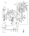
- an internal combustion engine system 1 which is preferably arranged in a motor vehicle, comprises an internal combustion engine 2, e.g. a piston engine which is fuel-operated in a conventional manner and which serves to generate mechanical drive power.
- an internal combustion engine 2 e.g. a piston engine which is fuel-operated in a conventional manner and which serves to generate mechanical drive power.
- a hydrocarbon such as e.g. Gasoline, diesel or natural gas.
- the fuel is supplied to the internal combustion engine 2 via a fuel line 3, in which a fuel delivery device 4, e.g. a pump is arranged.
- the fuel line 3 is connected to a fuel tank 5 in which the fuel is stored.
- a fresh gas line 6 is also connected, via which the internal combustion engine 2 with an oxygen-containing fresh gas, preferably air, is supplied.
- the engine system 1 includes an exhaust pipe 7 which is connected to the engine 2 and discharges the engine exhaust gas from the engine 2, which arises during operation of the internal combustion engine 2 in the combustion of the fuel.
- the exhaust pipe 7 contains in the shown Examples include a NOX storage 8, which is preferably formed by a NOX storage catalyst.
- the NOX storage 8 is designed such that it stores or stores NOX contained therein during its flow with engine exhaust gas.
- a particulate filter 9 may be arranged, which is preferably used in an engine 2 designed as a diesel engine and for cleaning particles, preferably soot particles, serving the engine exhaust carries.
- an oxidation catalyst 10 may be arranged, which serves in particular in the superstoichiometric operation of the internal combustion engine 2, ie in an operation with air or Excess oxygen to convert by incomplete combustion processes in the internal combustion engine 2 or not fully reacted hydrocarbons and carbon monoxide.
- the internal combustion engine system 1 is also equipped with a reformer 11, which serves to generate a hydrogen-containing reformate gas from a hydrogen-containing fuel and an oxygen-containing oxidizer.
- a reformer 11 which serves to generate a hydrogen-containing reformate gas from a hydrogen-containing fuel and an oxygen-containing oxidizer.
- Such reformers 11 are known, for example, from fuel cell systems and work, for example, with partial oxidation of a hydrocarbon, which can be realized, for example, in a strongly substoichiometric operation with the aid of a corresponding catalyst is.
- hydrocarbons such as gasoline, diesel, biodiesel and natural gas
- the hydrogen molecular or atomic, ie chemically bound, containing is expedient in which the reformer 11 uses the fuel as fuel, with which the internal combustion engine 2 is also operated.
- a fuel line 12 is provided, which is also connected to the fuel tank 5.
- the fuel line 12 supplies the reformer 11 with the fuel serving as fuel and for this purpose preferably contains a fuel delivery device 13, for example a pump.
- a fuel delivery device 13 for example a pump.
- an oxidizer line 14 is provided, in which a corresponding oxidizer conveyor 15, for example a blower, can be arranged.
- this oxidizer conveying device 15 realizes a lower pressure level than the internal combustion engine 2. Air is preferably used as the oxidizer.
- the internal combustion engine system 1 also equipped with a Reformateinleit Nurs 16, by means of which at least a portion of the reformate 11 generated by the reformer 11 is introduced into the exhaust pipe 7.
- the Reformateinleit driving 16 is suitably coupled to the reformer 11 and the exhaust pipe 7.
- the Reformateinleit Vietnamese 16 in this case comprises a reformate 17, the input side communicates with the reformer 11 and the output side via a discharge point 18 is connected to the exhaust pipe 7.
- the introduction point 18 is arranged upstream of the NOX storage 8 and downstream of the particle filter 9.
- the introduction point 18 is arranged upstream of the particle filter 9 and downstream of the oxidation catalyst 10.
- the introduction point 18 is arranged upstream of the oxidation catalytic converter 10.
- the three embodiments shown are not different. Other embodiments may result from combinations of the examples shown.
- the reformate introduction device 16 is designed such that it can initiate reformate gas upstream of the NOX storage 8 and / or upstream of the particulate filter 9 and / or upstream of the oxidation catalyst 10 into the exhaust gas line 7 as required.
- the reformate line 17 is connected via corresponding branches at least at two of the three discharge points 18 shown to the exhaust pipe 7.
- the targeted introduction of the reformate gas at the various discharge points can be realized, for example, with the aid of a corresponding valve device.
- a reformate heat exchanger 19 can be arranged in the reformate line 17. In this way, heat can be removed from the reformate gas with the aid of a suitable cooling medium before it is introduced into the exhaust gas line 7.
- the reformate heat exchanger 19 may be incorporated into a cooling circuit 20 of the internal combustion engine 2, so that it is the reformate line 17 with the cooling circuit 20 couples heat transfer. Accordingly, the heat withdrawn from the reformate gas can be removed via an already present cooling circuit. At the same time an optionally existing heat demand of the internal combustion engine 2 can be covered thereby at least partially.
- the reformate heat exchanger 19 is preferably designed so that the reformate gas cooled therein is in any case not cooled below the dew point temperature or condensation temperature in order to avoid condensation of water vapor and residual hydrocarbons contained in the reformate gas.
- the reformate initiator 16 may further comprise a reformate conveyor 21, e.g. a fan, a pump or a compressor, which is arranged in the reformate 17, and preferably downstream of the Reformat Vietnameseübertragers 19.
- a reformate conveyor 21 e.g. a fan, a pump or a compressor
- the ReformatINA110tragers 19 By the arrangement downstream of the Reformatskaübertragers 19, the Reformatbig Ranucil Ranucil can be realized comparatively inexpensive, since they only have to have a reduced temperature resistance. If the Oxidatoram dressed 15 is designed stronger and can realize a sufficient pressure level, it is in principle possible to dispense with the Reformatiliaerieerie 21 and / or on the Reformat Riversideübertrager 19.
- the Reformateinleit Vietnamese 16 may also be equipped with a valve device 42, which is preferably arranged downstream of the reformate conveyor 21 in the reformate 17.
- the valve device 42 serves to to prevent an undesirable backflow of engine exhaust gas through the reformate 17 to the reformer 11 and may be configured for this purpose, for example, as a non-return valve.
- there may further be a reformate reservoir 43 which is preferably connected to the reformate line 17 downstream of the reformate delivery device 21.
- the coupling between the Reformat acknowledged 43 and the Reformat effet 17 via the valve means 42, which then to implement appropriate switching states for charging the Reformat entitiess 43 with reformate from the reformer 11 and for discharging the Reformat entitiess 43 by introducing the reformate gas into the exhaust pipe.
- the engine system 1 is equipped with a controller 22, with the aid of the Reformateinleit Vietnamese 16 can be actuated.
- the controller 22 is suitably coupled to the reformate conveyor 21.
- the controller 22 may be coupled to a temperature sensor 23 which is disposed in or on the reformate line 17 downstream of the reformate heat exchanger 19 and determines the reformate gas temperature.
- the controller 22 is also coupled to the engine 2 or to a motor controller 24 coupled to the engine 2.
- the controller 22 and the motor controller 24 are arranged in a common control unit 25.
- the Engine control 24 actuates, for example, the fuel delivery device 4, which is expediently formed by an injection device.
- the engine controller 24 is coupled, for example, with a lambda probe 26, which determines the air ratio in the engine exhaust.
- the arrangement of the lambda probe 26 on or in the exhaust pipe 7 between the oxidation catalyst 10 and the particulate filter 9 is purely exemplary here; In particular, the lambda probe 26 can also be arranged between NOX storage 8 and particle filter 9 or downstream of the NOX storage 8 or upstream of the oxidation catalyst 10 on or in the exhaust gas line 7.
- the engine controller 24 may be coupled to a NOX probe 27 located downstream of the NOX reservoir 8 at or in the exhaust conduit 7 and capable of detecting NOX in the engine exhaust. For example, with the aid of such a NOX probe 27, the loading state of the NOX storage 8 can be determined. Once NOX probe 27 detects NOX in the engine exhaust, regeneration of NOX reservoir 8 is required.
- the vehicle equipped with the engine system 1 is also equipped with a fuel cell system 28, which is enclosed in FIG. 1 by a frame drawn with a broken line.
- the reformer 11 forms an integral part of this fuel cell system 28.
- the internal combustion engine system 1 according to the invention thus uses an already present on the vehicle component, namely the reformer 11 and its reformate gas for the regeneration of the NOX memory 8 and For the regeneration of the particulate filter 9 or for heating the particulate filter 9 or for heating the oxidation catalyst 10.
- the Reformateinleit styles 16 realizes the coupling between the fuel cell system 28 and the exhaust pipe. 7
- the fuel cell system 28 comprises in addition to the reformer 11 at least one fuel cell 29. This is used in a known manner for generating electric current from an anode gas containing hydrogen gas and a cathode gas containing oxygen gas.
- the reformate gas generated by the reformer 11 which is supplied to an anode side 30 of the fuel cell 29 via an anode gas line 31 which communicates with the reformer 11 on the input side, serves as anode gas.
- the coupling takes place between the reformate introduction device 16 and the fuel cell system 28.
- the reformate line 17 branches off from the anode gas line 31 connected to the reformer 11.
- the anode gas line 31 branches off from the reformate line 17 connected to the reformer 11.
- the anode side 30 is separated from a cathode side 33 by an electrolyte 32, which is in particular a membrane.
- the cathode side 33 is supplied with the cathode gas via a cathode gas line 34 in which a cathode gas delivery device 35, for example a blower, can be arranged.
- a cathode gas delivery device 35 for example a blower
- air is preferably used as the cathode gas.
- the fuel cell 29 has at least one electrical connection 36, on which electrical current can be tapped off during operation of the fuel cell 29.
- the fuel cell 29 can be configured as a high-temperature fuel cell, in particular as a solid fuel cell, so-called SOFC fuel cell. It is also possible to design the fuel cell 29 as a low-temperature fuel cell, in particular as a PEM fuel cell, which operates with a proton transport membrane or with a polymer electrolyte membrane. If it is a PEM fuel cell, the reformer 11 is suitably equipped with a CO gas purifier to reduce the carbon monoxide content in the refining gas.
- the fuel cell system 28 may be equipped with a residual gas burner 37 in which combustion of anode gas containing hydrogen gas takes place with cathode exhaust gas containing oxygen gas.
- the residual gas burner 37 may be integrated in the output side of the fuel cell 29, so that the fuel cell 29 and the residual gas burner 37 form a structural unit.
- the cathode exhaust gas is supplied to the residual gas burner 37 via a cathode exhaust gas line 38, while receiving the anode exhaust gas via an anode exhaust gas line 39.
- the fuel cell system 28 is preferably equipped with at least one heat exchanger 40, on the one hand in a burner exhaust line 41 and on the other hand, for example, in the Cathode gas line 34 is integrated.
- the heat exchanger 40 serves for heat-transmitting coupling of the burner exhaust gas generated by the residual gas burner 37 with the cathode gas to be supplied to the fuel cell 29.
- the heat exchanger 40 may be structurally integrated in the residual gas burner 37 on the output side. The residual gas burner 37 then forms a structural unit together with the heat exchanger 40.
- the fuel cell system 28 may also be provided with a recirculation line 44 which is connected on the one hand to the anode exhaust line 39 and on the other hand to the input side of the reformer 11. Via the recirculation line 44, hydrogen-containing anode exhaust gas can be supplied to the reforming process, which improves it.
- a recirculation heat exchanger 45 is preferably arranged, which also has e.g. is disposed in the Oxidator réelle 14.
- this recirculation heat exchanger 45 causes heating of the oxidizer, which improves the reforming process, and, on the other hand, cooling of the recirculated anode exhaust gas, allowing downstream of the recirculation heat exchanger 45 a comparatively inexpensive recirculation conveyor 46, e.g. a pump, a compressor or a blower, to be arranged in the recirculation line 45 for driving the anode exhaust gas.
- a comparatively inexpensive recirculation conveyor 46 e.g. a pump, a compressor or a blower
- the residual gas burner 37 can also the residual gas burner 37 with a cooling gas supply Be equipped 47, for example via a cooling gas line 48 to the residual gas burner 37, preferably on the cathode side, a suitable cooling gas, preferably air, feeds.
- a suitable cooling gas preferably air
- the cooling gas line 48 branches off the cathode gas line 34 at 49 upstream of the heat exchanger 40.
- a corresponding actuator 50 may be provided.
- the fuel cell system 28 is expediently equipped with a controller 51.
- This fuel cell system controller 51 communicates in a suitable manner with the controller 22 and / or with the motor controller 24 and may be arranged in the control unit 25, as here.
- the fuel cell system controller 51 with the conveyors 13, 15, 35, 46, with the actuator 50, with the reformer 11, with the fuel cell 29 and connected to the residual gas burner 37.
- the internal combustion engine system 1 operates as follows:
- the internal combustion engine 2 is operated stoichiometrically or slightly substoichiometrically, in any case not overstoichiometrically.
- the air ratio is 1.
- the air ratio is set to a value less than 1.0.
- the stoichiometric or slightly substoichiometric operation of the internal combustion engine 2 is set via the controller 22 or via the engine control 24.
- the controller 22 controls the reformate introducing means 16 to introduce reformate gas into the exhaust passage 7 upstream of the NOX storage 8 and between the particulate filter 9 and the NOX storage 8, respectively.
- the controller 22 operates, for example, the Reformatativ Republic Nurs 21 in a suitable manner.
- the generated during operation of the reformer 11 and during operation of the fuel cell system 28 Reformatgas is thus at least partially fed via the reformate 17 into the exhaust pipe 7, where it mixes with the engine exhaust and leads in the NOX memory 8 to the desired regeneration reaction.
- the controller 22 deactivates the reformate conveyor 21.
- the internal combustion engine 22 is returned to its normal operating state.
- the controller 22 actuates the Reformateinleit worn 16 for introducing reformate upstream of the particulate filter 9.
- the hot reformate gas can already cause the desired heating of the particulate filter 9 to the activation or light-off temperature of the regeneration reaction. Accordingly, it may be sufficient to introduce the reformate gas downstream of the oxidation catalyst 10 into the exhaust gas line 7.
- the reformate can be introduced upstream of the oxidation catalyst 10 in the exhaust pipe 7, so as to generate heat by the reaction of the hydrogen in the oxidation catalyst 10, which passes through the exhaust gas flow into the particulate filter 9 and this heats.
- the reformate introduction device 16 is actuated to introduce reformate gas into the exhaust gas line 7 when the internal combustion engine 2 is started, even if the air ratio is greater than 1.
- the reformate gas upstream of the NOX storage 8 or upstream of the oxidation catalyst 10 it is possible to bring the NOX storage 8 and / or the oxidation catalyst 10 to the respective operating temperature which the NOX storage 8 needs to reach the desired operating temperature To develop NOX storage function, and the oxidation catalyst 10 required to perform the desired oxidation of residual hydrocarbons and carbon monoxide.
Landscapes
- Engineering & Computer Science (AREA)
- Chemical & Material Sciences (AREA)
- Combustion & Propulsion (AREA)
- Mechanical Engineering (AREA)
- General Engineering & Computer Science (AREA)
- Chemical Kinetics & Catalysis (AREA)
- Health & Medical Sciences (AREA)
- Toxicology (AREA)
- Materials Engineering (AREA)
- Exhaust Gas After Treatment (AREA)
Applications Claiming Priority (1)
| Application Number | Priority Date | Filing Date | Title |
|---|---|---|---|
| DE102006054670A DE102006054670A1 (de) | 2006-11-17 | 2006-11-17 | Brennkraftmaschinensystem |
Publications (2)
| Publication Number | Publication Date |
|---|---|
| EP1925790A1 true EP1925790A1 (fr) | 2008-05-28 |
| EP1925790B1 EP1925790B1 (fr) | 2010-04-14 |
Family
ID=39184670
Family Applications (1)
| Application Number | Title | Priority Date | Filing Date |
|---|---|---|---|
| EP07120583A Active EP1925790B1 (fr) | 2006-11-17 | 2007-11-13 | Système de moteur à combustion interne |
Country Status (2)
| Country | Link |
|---|---|
| EP (1) | EP1925790B1 (fr) |
| DE (2) | DE102006054670A1 (fr) |
Cited By (1)
| Publication number | Priority date | Publication date | Assignee | Title |
|---|---|---|---|---|
| EP2233712A4 (fr) * | 2008-01-08 | 2011-05-04 | Honda Motor Co Ltd | Dispositif de purification des gaz d'échappement pour moteur à combustion interne |
Families Citing this family (1)
| Publication number | Priority date | Publication date | Assignee | Title |
|---|---|---|---|---|
| DE102012204649A1 (de) * | 2012-03-22 | 2013-09-26 | Volkswagen Aktiengesellschaft | Motoraggregat mit gasbetriebenen Verbrennungsmotor und Wasserstoffreformer und Verfahren zum Betreiben eines solchen Motoraggregats |
Citations (6)
| Publication number | Priority date | Publication date | Assignee | Title |
|---|---|---|---|---|
| EP1211394A2 (fr) * | 2000-11-30 | 2002-06-05 | Nissan Motor Co., Ltd. | Dispositif et procédé de purification de gaz d'échappement |
| DE10232737A1 (de) * | 2002-07-19 | 2004-02-05 | Audi Ag | Kraftfahrzeugaggregat |
| DE10237777A1 (de) * | 2002-08-17 | 2004-02-26 | Daimlerchrysler Ag | Brennkraftmaschine mit Reduktionsmittelerzeugungseinheit und Betriebsverfahren hierfür |
| WO2005054657A1 (fr) * | 2003-12-01 | 2005-06-16 | Shell Internationale Research Maatschappij B.V. | Procede de fonctionnement d'un moteur a combustion interne a allumage par compression en combinaison avec un reformeur catalytique |
| EP1582712A1 (fr) * | 2004-03-29 | 2005-10-05 | J. Eberspächer GmbH & Co. KG | Dispositif pour introduire du combustible dans la ligne d'échappement |
| WO2006069670A1 (fr) * | 2004-12-23 | 2006-07-06 | Bayerische Motoren Werke Aktiengesellschaft | Systeme forme d'une pile a combustible et d'un moteur a combustion interne |
Family Cites Families (8)
| Publication number | Priority date | Publication date | Assignee | Title |
|---|---|---|---|---|
| JPH05106430A (ja) * | 1991-10-16 | 1993-04-27 | Toyota Central Res & Dev Lab Inc | 内燃機関の窒素酸化物低減装置 |
| DE10054007A1 (de) * | 2000-11-01 | 2002-06-06 | Xcellsis Gmbh | Kraftfahrzeug mit einem Antriebsverbrennungsmotor |
| DE10203034A1 (de) * | 2002-01-26 | 2003-07-31 | Ballard Power Systems | Verfahren und Vorrichtung zur Reduzierung von Stickoxiden im Abgas einer Brennkraftmaschine |
| US20030226350A1 (en) * | 2002-06-11 | 2003-12-11 | Ke Liu | Reducing oxides of nitrogen using reformate generated from engine fuel, water and/or air |
| US20040052693A1 (en) * | 2002-09-18 | 2004-03-18 | Crane Samuel N. | Apparatus and method for removing NOx from the exhaust gas of an internal combustion engine |
| US6775973B2 (en) * | 2002-12-04 | 2004-08-17 | Hydrogensource Llc | Continuous flow, NOx-reduction adsorption unit for internal combustion engines |
| DE10301609A1 (de) * | 2003-01-17 | 2004-07-29 | Robert Bosch Gmbh | Kraftfahrzeug mit einer Brennkraftmaschine und einer Hilfsenergieversorgungseinrichtung |
| AT412845B (de) * | 2003-07-14 | 2005-08-25 | Alpps Fuel Cell Systems Gmbh | Abgasnachbehandlungssystem zur reduzierung der nox-emissionen von wärmekraftmaschinen mittels aus treibstoff erzeugtem reduktionsmittel |
-
2006
- 2006-11-17 DE DE102006054670A patent/DE102006054670A1/de not_active Withdrawn
-
2007
- 2007-11-13 EP EP07120583A patent/EP1925790B1/fr active Active
- 2007-11-13 DE DE502007003458T patent/DE502007003458D1/de active Active
Patent Citations (6)
| Publication number | Priority date | Publication date | Assignee | Title |
|---|---|---|---|---|
| EP1211394A2 (fr) * | 2000-11-30 | 2002-06-05 | Nissan Motor Co., Ltd. | Dispositif et procédé de purification de gaz d'échappement |
| DE10232737A1 (de) * | 2002-07-19 | 2004-02-05 | Audi Ag | Kraftfahrzeugaggregat |
| DE10237777A1 (de) * | 2002-08-17 | 2004-02-26 | Daimlerchrysler Ag | Brennkraftmaschine mit Reduktionsmittelerzeugungseinheit und Betriebsverfahren hierfür |
| WO2005054657A1 (fr) * | 2003-12-01 | 2005-06-16 | Shell Internationale Research Maatschappij B.V. | Procede de fonctionnement d'un moteur a combustion interne a allumage par compression en combinaison avec un reformeur catalytique |
| EP1582712A1 (fr) * | 2004-03-29 | 2005-10-05 | J. Eberspächer GmbH & Co. KG | Dispositif pour introduire du combustible dans la ligne d'échappement |
| WO2006069670A1 (fr) * | 2004-12-23 | 2006-07-06 | Bayerische Motoren Werke Aktiengesellschaft | Systeme forme d'une pile a combustible et d'un moteur a combustion interne |
Cited By (1)
| Publication number | Priority date | Publication date | Assignee | Title |
|---|---|---|---|---|
| EP2233712A4 (fr) * | 2008-01-08 | 2011-05-04 | Honda Motor Co Ltd | Dispositif de purification des gaz d'échappement pour moteur à combustion interne |
Also Published As
| Publication number | Publication date |
|---|---|
| EP1925790B1 (fr) | 2010-04-14 |
| DE102006054670A1 (de) | 2008-05-21 |
| DE502007003458D1 (de) | 2010-05-27 |
Similar Documents
| Publication | Publication Date | Title |
|---|---|---|
| EP1060942B1 (fr) | Véhicule ayant un moteur à combustion interne et un assemblage de cellules à combustible pour l'alimentation électrique du véhicule et méthode d' utilisation d'un tel vehicule | |
| EP2028350B1 (fr) | Système de moteur à combustion interne | |
| EP1947723B1 (fr) | Système d'approvisionnement d'énergie | |
| EP1845579A2 (fr) | Système de pile à combustible et procédé de fonctionnement correspondant | |
| DE102004028651B4 (de) | Brennkraftmaschine | |
| EP1986263B1 (fr) | Système de cellules combustibles et procédé de démarrage correspondant | |
| EP2058885A1 (fr) | Système de cellules combustibles | |
| DE112007001313T5 (de) | Hybrid-Antriebssystem mit Brennstoffzelle und Motor | |
| EP1925790B1 (fr) | Système de moteur à combustion interne | |
| EP1942537B1 (fr) | Système de pile à combustible avec un dispositif de régénération pour un reformeur et son procédé | |
| EP1519894A2 (fr) | Procede de demarrage d'un systeme generateur de gaz | |
| DE10257212A1 (de) | Brennstoffzellensystem und Verfahren zum Betreiben eines Brennstoffzellensystems | |
| DE10104607A1 (de) | Gaserzeugungssystem für ein Brennstoffzellensystem und Verfahren zum Betrieb eines Gaserzeugungssystems | |
| EP1919018B1 (fr) | Système de pile à combustible | |
| DE19950143A1 (de) | Brennstoffzellensystem | |
| DE102007033150B4 (de) | Betriebsverfahren für ein Brennstoffzellensystem | |
| EP2028710B1 (fr) | Véhicule avec un moteur à combustion et un système de cellules combustibles | |
| DE102007033151B4 (de) | Betriebsverfahren für ein Brennstoffzellensystem | |
| DE102008008907A1 (de) | Brennstoffzellensystem | |
| EP1739777B1 (fr) | Système de pile à combustible pour véhicules | |
| EP1657771B1 (fr) | Système de pile à combustible pour produire de l'éléctricité dans une véhicule avec moteur à combustion interne | |
| DE102006023857B4 (de) | Brennstoffzellensystem und zugehöriges Betriebsverfahren | |
| AT408041B (de) | Brennstoffzellenanordnung | |
| DE102010053572B4 (de) | Verfahren zum Betrieb eines Brennstoffzellensystems | |
| DE102005030474A1 (de) | Brennstoffzellensystem für ein Fahrzeug |
Legal Events
| Date | Code | Title | Description |
|---|---|---|---|
| PUAI | Public reference made under article 153(3) epc to a published international application that has entered the european phase |
Free format text: ORIGINAL CODE: 0009012 |
|
| AK | Designated contracting states |
Kind code of ref document: A1 Designated state(s): AT BE BG CH CY CZ DE DK EE ES FI FR GB GR HU IE IS IT LI LT LU LV MC MT NL PL PT RO SE SI SK TR |
|
| AX | Request for extension of the european patent |
Extension state: AL BA HR MK RS |
|
| 17P | Request for examination filed |
Effective date: 20081128 |
|
| 17Q | First examination report despatched |
Effective date: 20081230 |
|
| AKX | Designation fees paid |
Designated state(s): DE FR GB |
|
| GRAP | Despatch of communication of intention to grant a patent |
Free format text: ORIGINAL CODE: EPIDOSNIGR1 |
|
| GRAS | Grant fee paid |
Free format text: ORIGINAL CODE: EPIDOSNIGR3 |
|
| GRAA | (expected) grant |
Free format text: ORIGINAL CODE: 0009210 |
|
| AK | Designated contracting states |
Kind code of ref document: B1 Designated state(s): DE FR GB |
|
| REG | Reference to a national code |
Ref country code: GB Ref legal event code: FG4D Free format text: NOT ENGLISH |
|
| REF | Corresponds to: |
Ref document number: 502007003458 Country of ref document: DE Date of ref document: 20100527 Kind code of ref document: P |
|
| PLBE | No opposition filed within time limit |
Free format text: ORIGINAL CODE: 0009261 |
|
| STAA | Information on the status of an ep patent application or granted ep patent |
Free format text: STATUS: NO OPPOSITION FILED WITHIN TIME LIMIT |
|
| 26N | No opposition filed |
Effective date: 20110117 |
|
| REG | Reference to a national code |
Ref country code: FR Ref legal event code: ST Effective date: 20110801 |
|
| PG25 | Lapsed in a contracting state [announced via postgrant information from national office to epo] |
Ref country code: FR Free format text: LAPSE BECAUSE OF NON-PAYMENT OF DUE FEES Effective date: 20101130 |
|
| GBPC | Gb: european patent ceased through non-payment of renewal fee |
Effective date: 20111113 |
|
| PG25 | Lapsed in a contracting state [announced via postgrant information from national office to epo] |
Ref country code: GB Free format text: LAPSE BECAUSE OF NON-PAYMENT OF DUE FEES Effective date: 20111113 |
|
| REG | Reference to a national code |
Ref country code: FR Ref legal event code: CD Owner name: EBERSPACHER CLIMATE CONTROL SYSTEMS GMBH & CO. KG Effective date: 20131129 |
|
| REG | Reference to a national code |
Ref country code: DE Ref legal event code: R081 Ref document number: 502007003458 Country of ref document: DE Owner name: EBERSPAECHER CLIMATE CONTROL SYSTEMS GMBH & CO, DE Free format text: FORMER OWNER: J. EBERSPAECHER GMBH & CO. KG, 73730 ESSLINGEN, DE Effective date: 20131212 Ref country code: DE Ref legal event code: R082 Ref document number: 502007003458 Country of ref document: DE Representative=s name: BRP RENAUD & PARTNER, DE Effective date: 20131212 Ref country code: DE Ref legal event code: R082 Ref document number: 502007003458 Country of ref document: DE Representative=s name: BRP RENAUD UND PARTNER MBB RECHTSANWAELTE PATE, DE Effective date: 20131212 Ref country code: DE Ref legal event code: R082 Ref document number: 502007003458 Country of ref document: DE Representative=s name: BRP RENAUD UND PARTNER MBB, DE Effective date: 20131212 |
|
| REG | Reference to a national code |
Ref country code: FR Ref legal event code: TP Owner name: EBERSPACHER EXHAUST TECHNOLOGY GMBH & CO. KG, DE Effective date: 20140204 |
|
| REG | Reference to a national code |
Ref country code: FR Ref legal event code: TP Owner name: EBERSPACHER CLIMATE CONTROL SYSTEMS GMBH & CO., DE Effective date: 20150416 |
|
| PGFP | Annual fee paid to national office [announced via postgrant information from national office to epo] |
Ref country code: DE Payment date: 20241130 Year of fee payment: 18 |