EP1925862A2 - Integrable non-return valve - Google Patents
Integrable non-return valve Download PDFInfo
- Publication number
- EP1925862A2 EP1925862A2 EP07117534A EP07117534A EP1925862A2 EP 1925862 A2 EP1925862 A2 EP 1925862A2 EP 07117534 A EP07117534 A EP 07117534A EP 07117534 A EP07117534 A EP 07117534A EP 1925862 A2 EP1925862 A2 EP 1925862A2
- Authority
- EP
- European Patent Office
- Prior art keywords
- fluid channel
- closing element
- check valve
- sealing region
- sealing
- Prior art date
- Legal status (The legal status is an assumption and is not a legal conclusion. Google has not performed a legal analysis and makes no representation as to the accuracy of the status listed.)
- Granted
Links
- 238000007789 sealing Methods 0.000 claims abstract description 68
- 239000012530 fluid Substances 0.000 claims abstract description 61
- 238000004804 winding Methods 0.000 description 5
- 238000004519 manufacturing process Methods 0.000 description 4
- 230000004907 flux Effects 0.000 description 3
- 238000003780 insertion Methods 0.000 description 2
- 230000037431 insertion Effects 0.000 description 2
- 239000002775 capsule Substances 0.000 description 1
- 230000001419 dependent effect Effects 0.000 description 1
- 238000010137 moulding (plastic) Methods 0.000 description 1
Images


Classifications
-
- B—PERFORMING OPERATIONS; TRANSPORTING
- B60—VEHICLES IN GENERAL
- B60T—VEHICLE BRAKE CONTROL SYSTEMS OR PARTS THEREOF; BRAKE CONTROL SYSTEMS OR PARTS THEREOF, IN GENERAL; ARRANGEMENT OF BRAKING ELEMENTS ON VEHICLES IN GENERAL; PORTABLE DEVICES FOR PREVENTING UNWANTED MOVEMENT OF VEHICLES; VEHICLE MODIFICATIONS TO FACILITATE COOLING OF BRAKES
- B60T8/00—Arrangements for adjusting wheel-braking force to meet varying vehicular or ground-surface conditions, e.g. limiting or varying distribution of braking force
- B60T8/32—Arrangements for adjusting wheel-braking force to meet varying vehicular or ground-surface conditions, e.g. limiting or varying distribution of braking force responsive to a speed condition, e.g. acceleration or deceleration
- B60T8/34—Arrangements for adjusting wheel-braking force to meet varying vehicular or ground-surface conditions, e.g. limiting or varying distribution of braking force responsive to a speed condition, e.g. acceleration or deceleration having a fluid pressure regulator responsive to a speed condition
- B60T8/36—Arrangements for adjusting wheel-braking force to meet varying vehicular or ground-surface conditions, e.g. limiting or varying distribution of braking force responsive to a speed condition, e.g. acceleration or deceleration having a fluid pressure regulator responsive to a speed condition including a pilot valve responding to an electromagnetic force
- B60T8/3615—Electromagnetic valves specially adapted for anti-lock brake and traction control systems
- B60T8/363—Electromagnetic valves specially adapted for anti-lock brake and traction control systems in hydraulic systems
-
- B—PERFORMING OPERATIONS; TRANSPORTING
- B60—VEHICLES IN GENERAL
- B60T—VEHICLE BRAKE CONTROL SYSTEMS OR PARTS THEREOF; BRAKE CONTROL SYSTEMS OR PARTS THEREOF, IN GENERAL; ARRANGEMENT OF BRAKING ELEMENTS ON VEHICLES IN GENERAL; PORTABLE DEVICES FOR PREVENTING UNWANTED MOVEMENT OF VEHICLES; VEHICLE MODIFICATIONS TO FACILITATE COOLING OF BRAKES
- B60T15/00—Construction arrangement, or operation of valves incorporated in power brake systems and not covered by groups B60T11/00 or B60T13/00
- B60T15/02—Application and release valves
- B60T15/025—Electrically controlled valves
- B60T15/028—Electrically controlled valves in hydraulic systems
-
- B—PERFORMING OPERATIONS; TRANSPORTING
- B60—VEHICLES IN GENERAL
- B60T—VEHICLE BRAKE CONTROL SYSTEMS OR PARTS THEREOF; BRAKE CONTROL SYSTEMS OR PARTS THEREOF, IN GENERAL; ARRANGEMENT OF BRAKING ELEMENTS ON VEHICLES IN GENERAL; PORTABLE DEVICES FOR PREVENTING UNWANTED MOVEMENT OF VEHICLES; VEHICLE MODIFICATIONS TO FACILITATE COOLING OF BRAKES
- B60T8/00—Arrangements for adjusting wheel-braking force to meet varying vehicular or ground-surface conditions, e.g. limiting or varying distribution of braking force
- B60T8/32—Arrangements for adjusting wheel-braking force to meet varying vehicular or ground-surface conditions, e.g. limiting or varying distribution of braking force responsive to a speed condition, e.g. acceleration or deceleration
- B60T8/34—Arrangements for adjusting wheel-braking force to meet varying vehicular or ground-surface conditions, e.g. limiting or varying distribution of braking force responsive to a speed condition, e.g. acceleration or deceleration having a fluid pressure regulator responsive to a speed condition
- B60T8/341—Systems characterised by their valves
-
- F—MECHANICAL ENGINEERING; LIGHTING; HEATING; WEAPONS; BLASTING
- F16—ENGINEERING ELEMENTS AND UNITS; GENERAL MEASURES FOR PRODUCING AND MAINTAINING EFFECTIVE FUNCTIONING OF MACHINES OR INSTALLATIONS; THERMAL INSULATION IN GENERAL
- F16K—VALVES; TAPS; COCKS; ACTUATING-FLOATS; DEVICES FOR VENTING OR AERATING
- F16K31/00—Actuating devices; Operating means; Releasing devices
- F16K31/02—Actuating devices; Operating means; Releasing devices electric; magnetic
- F16K31/06—Actuating devices; Operating means; Releasing devices electric; magnetic using a magnet, e.g. diaphragm valves, cutting off by means of a liquid
- F16K31/0644—One-way valve
- F16K31/0655—Lift valves
-
- F—MECHANICAL ENGINEERING; LIGHTING; HEATING; WEAPONS; BLASTING
- F16—ENGINEERING ELEMENTS AND UNITS; GENERAL MEASURES FOR PRODUCING AND MAINTAINING EFFECTIVE FUNCTIONING OF MACHINES OR INSTALLATIONS; THERMAL INSULATION IN GENERAL
- F16K—VALVES; TAPS; COCKS; ACTUATING-FLOATS; DEVICES FOR VENTING OR AERATING
- F16K31/00—Actuating devices; Operating means; Releasing devices
- F16K31/02—Actuating devices; Operating means; Releasing devices electric; magnetic
- F16K31/06—Actuating devices; Operating means; Releasing devices electric; magnetic using a magnet, e.g. diaphragm valves, cutting off by means of a liquid
- F16K31/0686—Braking, pressure equilibration, shock absorbing
- F16K31/0693—Pressure equilibration of the armature
Definitions
- the invention relates to an integrable check valve according to the preamble of independent claim 1 and an associated solenoid valve with such a check valve.
- FIG. 1 A conventional solenoid valve, in particular for a hydraulic unit, which is used for example in an anti-lock braking system (ABS) or a traction control system (ASR system) or an electronic stability program system (ESP system) is in FIG. 1 shown.
- the conventional solenoid valve 1 comprises a magnetic flux generating magnet assembly 2 comprising a housing shell 3, a coil support 4, a coil winding 5 and a cover plate 6, and a valve cartridge 10 including a capsule 11, a valve core 12, an armature 13 with a plunger 14 and a return spring 15 includes.
- the magnet assembly 2 generates a magnetic force that moves the longitudinally movable armature 13 with the plunger 14 against the force of the return spring 15 against the valve core 12.
- the wound on the winding support 4 coil winding 5 forms an electrical coil, which is controlled via electrical connections 7.
- the armature 13 is counter to the force of the return spring 15 by energizing the coil winding 5 via the electrical connections 7 and the magnetic flux generated thereby by the solenoid assembly 2 via the cover 6 moved against the valve core 12.
- the valve core 12 receives the so-called valve body 16, which includes a main valve seat 17, in which the plunger 14 sealingly dives over a sealing cap to to implement the sealing function of the solenoid valve 1.
- the conventional solenoid valve 1 comprises a check valve 20 which performs a directional flow function.
- the check valve 20 of the conventional solenoid valve 1 comprises as essential parts a movable closing member 23, a valve seat 24 arranged in a check valve seat seat 22, a valve guide 24 and a stroke limiter 25 or system, the maximum stroke of the movable within the valve guide 24 closure member 23 limited.
- Known check valves, which are arranged within solenoid valves comprise at least three components and are usually part of the solenoid valve or its subassemblies. Therefore, the manufacture or assembly of the check valve is usually connected to the solenoid valve manufacturing or assembly.
- a first movable closing element comprises at least one guide element, at the end of a holding element is arranged.
- the at least one guide element is guided with the holding element in such a way through a fluid channel of a valve carrier, that the associated holding element is hooked at the other end of the fluid channel.
- the check valve according to the invention In the opened state of the fluid channel, in which a fluid flows in the predetermined direction through the fluid channel, a first sealing region of the fluid channel and a second sealing region of the closing element face each other with a predetermined distance and the associated holding element is at least partially on an edge of the fluid channel ,
- the fluid channel can be closed via the movable first closing element, the first sealing region and the second sealing region sealingly cooperating in the closed state of the fluid channel and prevent fluid flow.
- the check valve according to the invention can be used for example in solenoid valves, which are used in an anti-lock braking system (ABS) or a traction control system (ASR system) or an electronic stability program system (ESP system).
- ABS anti-lock braking system
- ASR traction control system
- ESP electronic stability program system
- the predetermined distance with which the first sealing region and the second sealing region in the open state of the fluid channel facing each other is predetermined by the stroke of the first closing element.
- the stroke of the first closing element can be predetermined, for example, over the length of the at least one guide element.
- the first closing element is designed as a fluidically connected to the fluid channel hollow body, in the interior of a third sealing region is formed and in which a second movable closing element is guided with a predetermined stroke, which has a fourth sealing area.
- the third sealing area and the fourth sealing area are opposite each other with a distance which is determined by the predetermined stroke of the second closing element.
- the third sealing area and the fourth sealing area cooperate sealingly and close the conductive connection to the fluid channel.
- the stroke of the second movable closing element can be predetermined, for example, by at least one limiting nose which protrudes into the interior of the first closing element, the second closing element in the opened state of the fluid channel abutting the at least one limiting nose and releasing the conductive connection to the fluid channel.
- This embodiment of the check valve advantageously allows a two-stage opening and closing of the fluid channel.
- the first closing element can be designed as a plastic molded part, wherein the second sealing area can be performed as a rounded sealing surface and the third sealing area can be performed as a sealing seat.
- the plastic moldings can be produced inexpensively and in bulk in an advantageous manner.
- the sealing areas of the first closing element are made soft by the use of plastic, whereby high tightness requirements, especially in ESP functions, can be met.
- the use of plastic increases the independence of form tolerances of the geometry of the valve carrier.
- the second closing element can for example be designed as a ball.
- the check valve according to the invention can be advantageously prepared and handled as a preassembled subassembly, which can simplify the manufacture of the solenoid valves and make it more flexible.
- the non-return valve in addition to the fluid channel, consists of only one part or of two parts and can be arranged flexibly and optimally in space in the solenoid valve.
- the check valve can be manufactured, assembled, and then easily integrated as a subassembly into the solenoid valve at any time, regardless of solenoid mounting.
- the check valve according to the invention can be completely integrated into the solenoid valve.
- Fig. 1 shows a schematic sectional view of a conventional solenoid valve.
- Fig. 2 shows a sectional view of a detail II Fig. 1 ,
- Fig. 3 shows a perspective sectional view of a section of a solenoid valve, the invention essential components of a first embodiment of a return valve shows.
- Fig. 4 shows a sectional view of the section of the solenoid valve according to Fig. 3 ,
- Fig. 5 to 7 each show an embodiment of an in 3 and 4 shown first closing element.
- Fig. 8 shows a schematic sectional view of a second embodiment of a check valve according to the invention in an open position.
- Fig. 9 shows a schematic sectional view of the second embodiment of the check valve according to the invention in a closed position.
- Fig. 10 shows a perspective view of a closing element of the second embodiment of a return valve according to 8 and 9 ,
- Fig. 11 shows a perspective sectional view of the closing element Fig. 10 along the section line XI-XI.
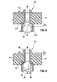
- the first embodiment of the check valve 30 according to the invention comprises a valve carrier 31, which has a fluid channel 39 and an associated first sealing region 32, and a movable first closing element 33, which has a second sealing region 33.1 and two guide elements 34, at the end of each one Holding element 35 is arranged.
- the guide elements 34 are guided through the fluid channel 39 such that the associated holding elements 35 are hooked at the other end of the fluid channel 39, ie the guide elements 34, the respective with
- the guide elements 34 connected holding elements 35 and the fluid channel 39 act upon insertion of the holding elements 35 together with the guide elements 34 in the fluid channel 39 and the outlet of the holding elements 35 from the fluid channel 39 in the manner of a clip connection.
- the distance at which the first sealing region 32 and the second sealing region 33.1 in the open state of the fluid channel 39 opposite each other, is determined by a stroke h1 of the first closing element 33, which is determined over the length of the guide elements 34.
- the fluid channel 39 of the check valve 30 is then opened when a fluid flows in a desired direction.
- the fluid channel 39 is closed by the movable with the stroke h1 first closing element 33 when the direction of fluid flow reverses, the first sealing region 32 and the second sealing region 33.1 sealingly cooperate in the closed state of the fluid channel 39.
- Fig. 5 to 7 show various embodiments of the first closing element 33.
- a first embodiment of the first closing element 33 has a spherical second sealing region 33.1 and a guide element 34 embodied as a rod, which is integrally formed on the second sealing region 33.1 and at the end of which a rod-shaped holding element 35 is arranged.
- a second embodiment of the first closing element 33 has a cap-shaped second sealing region 33.1 and designed as a rod guide member 34 which is integrally formed on the second sealing portion 33.1 and at the end of a holding member 35 is arranged in the form of an arrowhead.
- a third embodiment of the first closing element 33 has a hemispherical second sealing area 33.1 and a guide element 34 designed as a rod, which adjoins the second sealing area 33.1 is formed and at the end of a rod-shaped support member 35 is arranged.
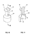
- the second embodiment of the check valve 30 according to the invention comprises a designed as a hollow body first closing element 33 which is conductively connected to the fluid channel 39 and in the interior of a third sealing region 36 is formed.
- a second movable closing element 37 is guided with a predeterminable stroke h2, which has a fourth sealing area 37.1.
- the second closing element 37 is designed as a ball in the illustrated embodiment.
- the stroke h2 of the second movable closing element 37 is predetermined by a plurality of limiting lugs 38 which protrude into the interior of the first closing element 33 and on which the second closing element 37 rests in the opened state of the check valve 30 and the conductive connection to the fluid channel 39 releases.
- the limiting tabs can be produced easily, for example by thermal deformation, preferably by ultrasonic deformation.
- the first closing element 33 of the second embodiment of the non-return valve 30 according to the invention makes possible, with the second closing element 37, a two-stage opening and closing of the fluid channel 39.
- the first closing element 33 can be executed in both described embodiments of the check valve 30 according to the invention, for example as a plastic molded part, wherein the second sealing region 33.1 is designed as a rounded sealing surface and the third sealing area is designed in the interior as a sealing seat 36.
- the design as a plastic part allows that the first closing element 33 can be produced very inexpensively and in bulk.
- plastic soft sealing areas 33.1, 36 whereby high tightness requirements, especially in ESP functions, can be met and result in a higher independence of the geometry and the shape tolerances of the first sealing portion 32 on the valve carrier 31.
- the first sealing region 32 on the valve carrier 31 in Fig. 3, 4 . 8 and 9 For example, formed as a hollow cone-shaped sealing seat.
- the first sealing region 32 in an embodiment which is not shown can also be designed as a sealing edge which sealingly cooperates with the second sealing region 33.1 of the first closing element in the closed state of the fluid channel 39.
- the check valve 30 according to the invention can be integrated for example in normally open or normally closed solenoid valves, which are used for example in an antilock braking system (ABS) or a traction control system (ASR system) or an electronic stability program system (ESP system), wherein the integrated check valve according to the invention directional flow function takes over.
- ABS antilock braking system
- ASR traction control system
- ESP electronic stability program system
- the check valve according to the invention can be manufactured and handled as a preassembled subassembly, wherein the subassembly consists of only two parts at most and can be flexibly and space optimally integrated in the solenoid valve.
- the check valve can be manufactured, assembled, and then easily integrated as a subassembly into the solenoid valve at any time, regardless of solenoid mounting.
- the production of the solenoid valves can be simplified or made more flexible in an advantageous manner.
Landscapes
- Engineering & Computer Science (AREA)
- Mechanical Engineering (AREA)
- Physics & Mathematics (AREA)
- General Engineering & Computer Science (AREA)
- Transportation (AREA)
- Fluid Mechanics (AREA)
- Electromagnetism (AREA)
- Magnetically Actuated Valves (AREA)
- Check Valves (AREA)
Abstract
Description
Die Erfindung betrifft ein integrierbares Rückschlagventil nach der Gattung des unabhängigen Patentanspruchs 1 und eine zugehöriges Magnetventil mit einem solchen Rückschlagventil.The invention relates to an integrable check valve according to the preamble of independent claim 1 and an associated solenoid valve with such a check valve.
Ein herkömmliches Magnetventil, insbesondere für ein Hydraulikaggregat, welches beispielsweise in einem Antiblockiersystem (ABS) oder einem Antriebsschlupfregelsystem (ASR-System) oder einem elektronischen Stabilitätsprogrammsystem (ESP-System) eingesetzt wird, ist in
Das erfindungsgemäße Rückschlagventil mit den Merkmalen des unabhängigen Patentanspruchs 1 hat demgegenüber den Vorteil, dass ein erstes bewegliches Schließelement mindestens ein Führungselement umfasst, an dessen Ende ein Halteelement angeordnet ist. Das mindestens eine Führungselement ist mit dem Halteelement derart durch einen Fluidkanal eines Ventilträgers geführt, dass das zugehörige Halteelement am anderen Ende des Fluidkanals verhakt ist. Das bedeutet, dass das mindestens eine Führungselement, das jeweilige mit dem mindestens einen Führungselement verbundene Halteelement und der Fluidkanal jeweils beispielsweise nach Art einer Clipsverbindung zusammenwirken. Im geöffneten Zustand des Fluidkanals, in dem ein Fluid in der vorgegebenen Richtung durch den Fluidkanal fließt, liegen ein erster Dichtbereich des Fluidkanals und ein zweiter Dichtbereich des Schließelements einander mit einem vorgegebenen Abstand gegenüber und das zugehörige Halteelement liegt mindestens teilweise auf einem Rand des Fluidkanals auf. Der Fluidkanal kann über das bewegliche erste Schließelement geschlossen werden, wobei der erste Dichtbereich und der zweite Dichtbereich im geschlossenen Zustand des Fluidkanals dichtend zusammenwirken und einen Fluidfluss verhindern. Durch das erfindungsgemäße Rückschlagventil kann die erforderliche Teileanzahl in vorteilhafter Weise reduziert werden, da auf die aus dem Stand der Technik bekannte und in
Das erfindungsgemäße Rückschlagventil kann beispielsweise in Magnetventilen verwendet werden, die in einem Antiblockiersystem (ABS) oder einem Antriebsschlupfregelsystem (ASR-System) oder einem elektronischen Stabilitätsprogrammsystem (ESP-System) eingesetzt werden.The check valve according to the invention can be used for example in solenoid valves, which are used in an anti-lock braking system (ABS) or a traction control system (ASR system) or an electronic stability program system (ESP system).
Durch die in den abhängigen Ansprüchen aufgeführten Maßnahmen und Weiterbildungen sind vorteilhafte Verbesserungen des im unabhängigen Patentanspruch 1 angegebenen Rückschlagventils möglich.The measures and refinements recited in the dependent claims advantageous improvements of the independent claim 1 check valve are possible.
Besonders vorteilhaft ist, dass der vorgegebene Abstand, mit dem der erste Dichtbereich und der zweite Dichtbereich im geöffneten Zustand des Fluidkanals einander gegenüberliegen, durch den Hub des ersten Schließelements vorgegeben ist. Der Hub des ersten Schließelements kann beispielsweise über die Länge des mindestens einen Führungselements vorgegeben werden.It is particularly advantageous that the predetermined distance with which the first sealing region and the second sealing region in the open state of the fluid channel facing each other, is predetermined by the stroke of the first closing element. The stroke of the first closing element can be predetermined, for example, over the length of the at least one guide element.
In weiterer Ausgestaltung des erfindungsgemäßen Rückschlagventils ist das erste Schließelement als ein mit dem Fluidkanal leitend verbundener Hohlkörper ausgeführt, in dessen Innenraum ein dritter Dichtbereich ausgebildet ist und in dem ein zweites bewegliches Schließelement mit einem vorgebbaren Hub geführt ist, das einen vierten Dichtbereich aufweist. Im geöffneten Zustand des Fluidkanals liegen der dritte Dichtbereich und der vierte Dichtbereich einander mit einem Abstand gegenüber, der vom vorgegebenen Hub des zweiten Schließelements bestimmt ist. Im geschlossenen Zustand des Fluidkanals wirken der dritte Dichtbereich und der vierte Dichtbereich dichtend zusammen und schließen die leitende Verbindung zum Fluidkanal. Der Hub des zweiten beweglichen Schließelements kann beispielsweise durch mindestens eine Begrenzungsnase vorgegeben werden, die in den Innenraum des ersten Schließelements ragt, wobei das zweite Schließelement im geöffneten Zustand des Fluidkanals an der mindestens einen Begrenzungsnase anliegt und die leitende Verbindung zum Fluidkanal freigibt. Diese Ausführungsform des Rückschlagventils ermöglicht in vorteilhafter Weise ein zweistufiges Öffnen und Schließen des Fluidkanals.In a further embodiment of the check valve according to the invention, the first closing element is designed as a fluidically connected to the fluid channel hollow body, in the interior of a third sealing region is formed and in which a second movable closing element is guided with a predetermined stroke, which has a fourth sealing area. In the open state of the fluid channel, the third sealing area and the fourth sealing area are opposite each other with a distance which is determined by the predetermined stroke of the second closing element. In the closed state of the fluid channel, the third sealing area and the fourth sealing area cooperate sealingly and close the conductive connection to the fluid channel. The stroke of the second movable closing element can be predetermined, for example, by at least one limiting nose which protrudes into the interior of the first closing element, the second closing element in the opened state of the fluid channel abutting the at least one limiting nose and releasing the conductive connection to the fluid channel. This embodiment of the check valve advantageously allows a two-stage opening and closing of the fluid channel.
In weiterer Ausgestaltung des erfindungsgemäßen Rückschlagventils kann das erste Schließelement als Kunststoffformteil ausgeführt werden, wobei der zweite Dichtbereich als abgerundete Dichtfläche ausgeführt werden kann und der dritte Dichtbereich als Dichtsitz ausgeführt werden kann. Die Kunststoffformteile können in vorteilhafte Weise kostengünstig und massenhaft hergestellt werden. Weiterhin sind die Dichtbereiche des ersten Schließelements durch die Verwendung von Kunststoff weich ausgeführt, wodurch hohe Dichtheitsanforderungen, insbesondere bei ESP-Funktionen, erfüllt werden können. Zudem wird durch die Verwendung von Kunststoff die Unabhängigkeit von Formtoleranzen der Geometrie des Ventilträgers erhöht. Das zweite Schließelement kann beispielsweise als Kugel ausgeführt werden.In a further embodiment of the check valve according to the invention, the first closing element can be designed as a plastic molded part, wherein the second sealing area can be performed as a rounded sealing surface and the third sealing area can be performed as a sealing seat. The plastic moldings can be produced inexpensively and in bulk in an advantageous manner. Furthermore, the sealing areas of the first closing element are made soft by the use of plastic, whereby high tightness requirements, especially in ESP functions, can be met. In addition, the use of plastic increases the independence of form tolerances of the geometry of the valve carrier. The second closing element can for example be designed as a ball.
Das erfindungsgemäße Rückschlagventil kann in vorteilhafter Weise als vormontagefähige Unterbaugruppe hergestellt und gehandhabt werden, wodurch sich die Fertigung der Magnetventile vereinfachen bzw. flexibler gestalten lässt. Das Rückschlagventil besteht je nach Ausführungsform zusätzlich zum Fluidkanal aus nur einem Teil oder aus zwei Teilen und lässt sich flexibel und bauraumoptimal im Magnetventil anordnen. Das Rückschlagventil kann unabhängig von der Magnetventilmontage gefertigt, montiert und dann zu beliebigen Zeitpunkten als Unterbaugruppe in das Magnetventil einfach integriert werden. Zudem kann das erfindungsgemäße Rückschlagventil vollständig in das Magnetventil integriert werden.The check valve according to the invention can be advantageously prepared and handled as a preassembled subassembly, which can simplify the manufacture of the solenoid valves and make it more flexible. Depending on the embodiment, the non-return valve, in addition to the fluid channel, consists of only one part or of two parts and can be arranged flexibly and optimally in space in the solenoid valve. The check valve can be manufactured, assembled, and then easily integrated as a subassembly into the solenoid valve at any time, regardless of solenoid mounting. In addition, the check valve according to the invention can be completely integrated into the solenoid valve.
Vorteilhafte, nachfolgend beschriebene Ausführungsformen der Erfindung sowie das zu deren besserem Verständnis oben erläuterte, herkömmliche Ausführungsbeispiel sind in den Zeichnungen dargestellt. Zudem bezeichnen in den Zeichnungen gleiche Bezugszeichen Elemente bzw. Komponenten, die gleiche bzw. analoge Funktionen ausführen.Advantageous embodiments of the invention described below as well as the conventional embodiment explained above for better understanding thereof are shown in the drawings. In addition, in the drawings, like reference characters designate elements or components that perform the same or analog functions.
Wie aus
Wie aus
Wie weiter aus
Wie weiter aus
Das erste Schließelement 33 der zweiten Ausführungsform des erfindungsgemäßen Rückschlagventils 30 ermöglicht mit dem zweiten Schließelement 37 ein zweistufiges Öffnen und Schließen des Fluidkanals 39.The
Das erste Schließelement 33 kann in beiden beschriebenen Ausführungsformen des erfindungsgemäßen Rückschlagventils 30 beispielsweise als Kunststoffformteil ausgeführt werden, wobei der zweite Dichtbereich 33.1 als abgerundete Dichtfläche ausgeführt ist und der dritte Dichtbereich im Innenraum als Dichtsitz 36 ausgeführt ist. Die Ausführung als Kunststoffteil ermöglicht, dass das erste Schließelement 33 sehr kostengünstig und massenhaft hergestellt werden kann. Zudem ergeben sich durch die Verwendung von Kunststoff weiche Dichtbereiche 33.1, 36, wodurch hohe Dichtheitsanforderungen, insbesondere bei ESP- Funktionen, erfüllt werden können und sich eine höhere Unabhängigkeit von der Geometrie und den Formtoleranzen des ersten Dichtbereichs 32 am Ventilträger 31 ergeben. So ist der erste Dichtbereich 32 am Ventilträger 31 in
Das erfindungsgemäße Rückschlagventil 30 kann beispielsweise in stromlos offene oder stromlos geschlossene Magnetventile integriert werden, die beispielsweise in einem Antiblockiersystem (ABS) oder einem Antriebsschlupfregelsystem (ASR-System) oder einem elektronischen Stabilitätsprogrammsystem (ESP-System) eingesetzt werden, wobei das integrierte erfindungsgemäße Rückschlagventil die richtungsorientierte Durchflussfunktion übernimmt.The
Das erfindungsgemäße Rückschlagventil kann als vormontagefähige Unterbaugruppe hergestellt und gehandhabt werden, wobei die Unterbaugruppe maximal nur aus zwei Teilen besteht und flexibel und bauraumoptimal im Magnetventil integriert werden kann. Das bedeutet, dass das Rückschlagventil unabhängig von der Magnetventilmontage gefertigt, montiert und dann zu beliebigen Zeitpunkten als Unterbaugruppe in das Magnetventil einfach integriert werden kann. Dadurch lässt sich in vorteilhafter Weise die Fertigung der Magnetventile vereinfachen bzw. flexibler gestalten.The check valve according to the invention can be manufactured and handled as a preassembled subassembly, wherein the subassembly consists of only two parts at most and can be flexibly and space optimally integrated in the solenoid valve. This means that the check valve can be manufactured, assembled, and then easily integrated as a subassembly into the solenoid valve at any time, regardless of solenoid mounting. As a result, the production of the solenoid valves can be simplified or made more flexible in an advantageous manner.
Claims (10)
Applications Claiming Priority (1)
| Application Number | Priority Date | Filing Date | Title |
|---|---|---|---|
| DE102006055832A DE102006055832A1 (en) | 2006-11-27 | 2006-11-27 | Integral check valve |
Publications (3)
| Publication Number | Publication Date |
|---|---|
| EP1925862A2 true EP1925862A2 (en) | 2008-05-28 |
| EP1925862A3 EP1925862A3 (en) | 2010-06-09 |
| EP1925862B1 EP1925862B1 (en) | 2013-01-23 |
Family
ID=39048927
Family Applications (1)
| Application Number | Title | Priority Date | Filing Date |
|---|---|---|---|
| EP07117534A Not-in-force EP1925862B1 (en) | 2006-11-27 | 2007-09-28 | Integrable non-return valve |
Country Status (2)
| Country | Link |
|---|---|
| EP (1) | EP1925862B1 (en) |
| DE (1) | DE102006055832A1 (en) |
Families Citing this family (1)
| Publication number | Priority date | Publication date | Assignee | Title |
|---|---|---|---|---|
| DE102011005487A1 (en) | 2011-03-14 | 2012-09-20 | Robert Bosch Gmbh | Valve device, in particular outlet valve of a high-pressure fuel pump of an internal combustion engine |
Citations (2)
| Publication number | Priority date | Publication date | Assignee | Title |
|---|---|---|---|---|
| US4570669A (en) | 1982-08-24 | 1986-02-18 | Pauliukonis Richard S | Simplified springless check valve |
| DE19955888A1 (en) | 1999-11-20 | 2001-05-23 | Bosch Gmbh Robert | Magnetic valve for slip-free hydraulic braking system for car comprises main valve and check valve with rigid valve body and tapering hollow valve seat, valve body being fitted with elastomeric sealing ring |
Family Cites Families (3)
| Publication number | Priority date | Publication date | Assignee | Title |
|---|---|---|---|---|
| JPS6080161U (en) * | 1983-11-09 | 1985-06-04 | 北海道水道機材株式会社 | intake valve |
| IT222707Z2 (en) * | 1991-07-22 | 1995-04-24 | Zani Gianmauro | SAFETY VALVE FOR PRESSURE CONTAINERS, PARTICULARLY SUITABLE FOR BEING USED ON COFFEE MACHINES, BOILERS FOR IRON IRON STEAM WASHER AND SIMILAR |
| JP4613472B2 (en) * | 2001-10-12 | 2011-01-19 | 東洋製罐株式会社 | Tube container with check valve |
-
2006
- 2006-11-27 DE DE102006055832A patent/DE102006055832A1/en not_active Withdrawn
-
2007
- 2007-09-28 EP EP07117534A patent/EP1925862B1/en not_active Not-in-force
Patent Citations (2)
| Publication number | Priority date | Publication date | Assignee | Title |
|---|---|---|---|---|
| US4570669A (en) | 1982-08-24 | 1986-02-18 | Pauliukonis Richard S | Simplified springless check valve |
| DE19955888A1 (en) | 1999-11-20 | 2001-05-23 | Bosch Gmbh Robert | Magnetic valve for slip-free hydraulic braking system for car comprises main valve and check valve with rigid valve body and tapering hollow valve seat, valve body being fitted with elastomeric sealing ring |
Also Published As
| Publication number | Publication date |
|---|---|
| EP1925862A3 (en) | 2010-06-09 |
| DE102006055832A1 (en) | 2008-05-29 |
| EP1925862B1 (en) | 2013-01-23 |
Similar Documents
| Publication | Publication Date | Title |
|---|---|---|
| EP2091797B1 (en) | Solenoid valve | |
| EP2209679B1 (en) | Valve cartridge for a solenoid valve, and associated solenoid valve | |
| EP2114740B1 (en) | Solenoid valve | |
| WO1998031577A1 (en) | Magnetic valve | |
| DE102015218263A1 (en) | magnetic valve | |
| DE102008004780A1 (en) | valve assembly | |
| WO2008043618A1 (en) | Solenoid valve and associated hydraulic braking system for motor vehicles | |
| DE102016205988A1 (en) | Valve anchor for a solenoid valve and corresponding solenoid valve | |
| DE102017222633A1 (en) | Solenoid valve and method for producing a solenoid valve | |
| DE102007033060C5 (en) | Solenoid valve with axially adjustable distance between pole core and return plate | |
| DE102006054185A1 (en) | magnetic valve | |
| DE102016201474B4 (en) | Valve armature for a solenoid valve and valve cartridge for a solenoid valve | |
| WO2018041548A1 (en) | Valve armature and valve cartridge for a solenoid valve | |
| DE19932747B4 (en) | Method for producing a pressure regulating valve for an automatic transmission of a motor vehicle and pressure regulating valve produced by the method | |
| EP1925862B1 (en) | Integrable non-return valve | |
| EP3141737A1 (en) | Valve for metering a fluid | |
| DE102005061409A1 (en) | Electromagnetic fuel injection valve for vehicles is closed by ball whose top fits against curved section at tip of valve needle | |
| DE102014202334A1 (en) | High pressure pump for a fuel injection system | |
| EP1682802B1 (en) | Valve for controlling fluids, comprising a multifunctional component | |
| EP2519432A1 (en) | Solenoid valve, and method for producing such a solenoid valve | |
| DE102019210666A1 (en) | Pump device for a brake system of a motor vehicle, brake system | |
| EP4449456A1 (en) | Electromagnetic device, and method for producing an electromagnetic device of this kind | |
| DE102006052629B4 (en) | magnetic valve | |
| DE102011086316A1 (en) | Electroless open or closed magnetic valves for e.g. anti-skid system, have cover connected with cladding that is arranged within magnetically conductive housing and wrapped on region of valve assemblies, where region acts as carriers | |
| EP1981746A1 (en) | Hydraulic unit |
Legal Events
| Date | Code | Title | Description |
|---|---|---|---|
| PUAI | Public reference made under article 153(3) epc to a published international application that has entered the european phase |
Free format text: ORIGINAL CODE: 0009012 |
|
| AK | Designated contracting states |
Kind code of ref document: A2 Designated state(s): AT BE BG CH CY CZ DE DK EE ES FI FR GB GR HU IE IS IT LI LT LU LV MC MT NL PL PT RO SE SI SK TR |
|
| AX | Request for extension of the european patent |
Extension state: AL BA HR MK RS |
|
| PUAL | Search report despatched |
Free format text: ORIGINAL CODE: 0009013 |
|
| AK | Designated contracting states |
Kind code of ref document: A3 Designated state(s): AT BE BG CH CY CZ DE DK EE ES FI FR GB GR HU IE IS IT LI LT LU LV MC MT NL PL PT RO SE SI SK TR |
|
| AX | Request for extension of the european patent |
Extension state: AL BA HR MK RS |
|
| 17P | Request for examination filed |
Effective date: 20101209 |
|
| AKX | Designation fees paid |
Designated state(s): DE FR GB |
|
| 17Q | First examination report despatched |
Effective date: 20110321 |
|
| RIC1 | Information provided on ipc code assigned before grant |
Ipc: F16K 15/04 20060101AFI20120903BHEP Ipc: F16K 31/06 20060101ALN20120903BHEP Ipc: B60T 8/36 20060101ALN20120903BHEP |
|
| GRAP | Despatch of communication of intention to grant a patent |
Free format text: ORIGINAL CODE: EPIDOSNIGR1 |
|
| RIN1 | Information on inventor provided before grant (corrected) |
Inventor name: VIER, ELMAR Inventor name: FRICKE-SCHMIDT, JOERG Inventor name: FINK, REINHARD |
|
| GRAS | Grant fee paid |
Free format text: ORIGINAL CODE: EPIDOSNIGR3 |
|
| GRAA | (expected) grant |
Free format text: ORIGINAL CODE: 0009210 |
|
| AK | Designated contracting states |
Kind code of ref document: B1 Designated state(s): DE FR GB |
|
| REG | Reference to a national code |
Ref country code: GB Ref legal event code: FG4D Free format text: NOT ENGLISH |
|
| REG | Reference to a national code |
Ref country code: DE Ref legal event code: R096 Ref document number: 502007011254 Country of ref document: DE Effective date: 20130314 |
|
| PLBE | No opposition filed within time limit |
Free format text: ORIGINAL CODE: 0009261 |
|
| STAA | Information on the status of an ep patent application or granted ep patent |
Free format text: STATUS: NO OPPOSITION FILED WITHIN TIME LIMIT |
|
| 26N | No opposition filed |
Effective date: 20131024 |
|
| REG | Reference to a national code |
Ref country code: DE Ref legal event code: R097 Ref document number: 502007011254 Country of ref document: DE Effective date: 20131024 |
|
| GBPC | Gb: european patent ceased through non-payment of renewal fee |
Effective date: 20130928 |
|
| REG | Reference to a national code |
Ref country code: FR Ref legal event code: ST Effective date: 20140530 |
|
| PG25 | Lapsed in a contracting state [announced via postgrant information from national office to epo] |
Ref country code: GB Free format text: LAPSE BECAUSE OF NON-PAYMENT OF DUE FEES Effective date: 20130928 |
|
| PG25 | Lapsed in a contracting state [announced via postgrant information from national office to epo] |
Ref country code: FR Free format text: LAPSE BECAUSE OF NON-PAYMENT OF DUE FEES Effective date: 20130930 |
|
| REG | Reference to a national code |
Ref country code: DE Ref legal event code: R084 Ref document number: 502007011254 Country of ref document: DE |
|
| PGFP | Annual fee paid to national office [announced via postgrant information from national office to epo] |
Ref country code: DE Payment date: 20201121 Year of fee payment: 14 |
|
| REG | Reference to a national code |
Ref country code: DE Ref legal event code: R119 Ref document number: 502007011254 Country of ref document: DE |
|
| PG25 | Lapsed in a contracting state [announced via postgrant information from national office to epo] |
Ref country code: DE Free format text: LAPSE BECAUSE OF NON-PAYMENT OF DUE FEES Effective date: 20220401 |