EP1925873A1 - Behälter zum Lagern von Flüssigkeiten unter Hochdruck, insbesondere eines Gases zum Betanken eines Kraftfahrzeugmotors und Verfahren zu seiner Herstellung - Google Patents
Behälter zum Lagern von Flüssigkeiten unter Hochdruck, insbesondere eines Gases zum Betanken eines Kraftfahrzeugmotors und Verfahren zu seiner Herstellung Download PDFInfo
- Publication number
- EP1925873A1 EP1925873A1 EP06425803A EP06425803A EP1925873A1 EP 1925873 A1 EP1925873 A1 EP 1925873A1 EP 06425803 A EP06425803 A EP 06425803A EP 06425803 A EP06425803 A EP 06425803A EP 1925873 A1 EP1925873 A1 EP 1925873A1
- Authority
- EP
- European Patent Office
- Prior art keywords
- terminal region
- tank
- portions
- area
- defining
- Prior art date
- Legal status (The legal status is an assumption and is not a legal conclusion. Google has not performed a legal analysis and makes no representation as to the accuracy of the status listed.)
- Granted
Links
- 239000012530 fluid Substances 0.000 title claims abstract description 18
- 238000004519 manufacturing process Methods 0.000 title claims description 6
- 229910000831 Steel Inorganic materials 0.000 claims abstract description 22
- 239000010959 steel Substances 0.000 claims abstract description 22
- 238000000034 method Methods 0.000 claims description 19
- 238000005242 forging Methods 0.000 claims description 6
- OKTJSMMVPCPJKN-UHFFFAOYSA-N Carbon Chemical compound [C] OKTJSMMVPCPJKN-UHFFFAOYSA-N 0.000 claims description 4
- 229910052799 carbon Inorganic materials 0.000 claims description 4
- 238000005488 sandblasting Methods 0.000 claims description 3
- 238000009499 grossing Methods 0.000 claims description 2
- 239000011159 matrix material Substances 0.000 claims description 2
- 239000004576 sand Substances 0.000 claims description 2
- XLYOFNOQVPJJNP-UHFFFAOYSA-N water Substances O XLYOFNOQVPJJNP-UHFFFAOYSA-N 0.000 claims description 2
- 230000000875 corresponding effect Effects 0.000 claims 3
- 230000000903 blocking effect Effects 0.000 claims 1
- 230000002596 correlated effect Effects 0.000 claims 1
- 238000010438 heat treatment Methods 0.000 claims 1
- 229910000677 High-carbon steel Inorganic materials 0.000 abstract 1
- 239000007789 gas Substances 0.000 description 21
- VNWKTOKETHGBQD-UHFFFAOYSA-N methane Chemical compound C VNWKTOKETHGBQD-UHFFFAOYSA-N 0.000 description 10
- 238000003860 storage Methods 0.000 description 8
- 230000015572 biosynthetic process Effects 0.000 description 5
- 238000010276 construction Methods 0.000 description 5
- 239000000446 fuel Substances 0.000 description 3
- 238000009434 installation Methods 0.000 description 3
- 229910000851 Alloy steel Inorganic materials 0.000 description 2
- 229910000975 Carbon steel Inorganic materials 0.000 description 2
- 230000002411 adverse Effects 0.000 description 2
- 238000002485 combustion reaction Methods 0.000 description 2
- 230000000694 effects Effects 0.000 description 2
- 238000007731 hot pressing Methods 0.000 description 2
- 238000010297 mechanical methods and process Methods 0.000 description 2
- 230000005226 mechanical processes and functions Effects 0.000 description 2
- 238000005728 strengthening Methods 0.000 description 2
- UFHFLCQGNIYNRP-UHFFFAOYSA-N Hydrogen Chemical compound [H][H] UFHFLCQGNIYNRP-UHFFFAOYSA-N 0.000 description 1
- XCNJCXWPYFLAGR-UHFFFAOYSA-N chromium manganese Chemical compound [Cr].[Mn].[Mn].[Mn] XCNJCXWPYFLAGR-UHFFFAOYSA-N 0.000 description 1
- VNTLIPZTSJSULJ-UHFFFAOYSA-N chromium molybdenum Chemical compound [Cr].[Mo] VNTLIPZTSJSULJ-UHFFFAOYSA-N 0.000 description 1
- 239000002131 composite material Substances 0.000 description 1
- 238000009792 diffusion process Methods 0.000 description 1
- 238000005516 engineering process Methods 0.000 description 1
- 239000002828 fuel tank Substances 0.000 description 1
- 229910052739 hydrogen Inorganic materials 0.000 description 1
- 239000001257 hydrogen Substances 0.000 description 1
- 239000000463 material Substances 0.000 description 1
- 239000003345 natural gas Substances 0.000 description 1
- 238000003825 pressing Methods 0.000 description 1
- 230000000750 progressive effect Effects 0.000 description 1
- 230000000284 resting effect Effects 0.000 description 1
- 230000003068 static effect Effects 0.000 description 1
- 238000011179 visual inspection Methods 0.000 description 1
- 238000003466 welding Methods 0.000 description 1
Images


Classifications
-
- F—MECHANICAL ENGINEERING; LIGHTING; HEATING; WEAPONS; BLASTING
- F17—STORING OR DISTRIBUTING GASES OR LIQUIDS
- F17C—VESSELS FOR CONTAINING OR STORING COMPRESSED, LIQUEFIED OR SOLIDIFIED GASES; FIXED-CAPACITY GAS-HOLDERS; FILLING VESSELS WITH, OR DISCHARGING FROM VESSELS, COMPRESSED, LIQUEFIED, OR SOLIDIFIED GASES
- F17C1/00—Pressure vessels, e.g. gas cylinder, gas tank, replaceable cartridge
- F17C1/005—Storage of gas or gaseous mixture at high pressure and at high density condition, e.g. in the single state phase
-
- F—MECHANICAL ENGINEERING; LIGHTING; HEATING; WEAPONS; BLASTING
- F17—STORING OR DISTRIBUTING GASES OR LIQUIDS
- F17C—VESSELS FOR CONTAINING OR STORING COMPRESSED, LIQUEFIED OR SOLIDIFIED GASES; FIXED-CAPACITY GAS-HOLDERS; FILLING VESSELS WITH, OR DISCHARGING FROM VESSELS, COMPRESSED, LIQUEFIED, OR SOLIDIFIED GASES
- F17C2201/00—Vessel construction, in particular geometry, arrangement or size
- F17C2201/01—Shape
- F17C2201/0104—Shape cylindrical
- F17C2201/0109—Shape cylindrical with exteriorly curved end-piece
-
- F—MECHANICAL ENGINEERING; LIGHTING; HEATING; WEAPONS; BLASTING
- F17—STORING OR DISTRIBUTING GASES OR LIQUIDS
- F17C—VESSELS FOR CONTAINING OR STORING COMPRESSED, LIQUEFIED OR SOLIDIFIED GASES; FIXED-CAPACITY GAS-HOLDERS; FILLING VESSELS WITH, OR DISCHARGING FROM VESSELS, COMPRESSED, LIQUEFIED, OR SOLIDIFIED GASES
- F17C2201/00—Vessel construction, in particular geometry, arrangement or size
- F17C2201/05—Size
- F17C2201/056—Small (<1 m3)
-
- F—MECHANICAL ENGINEERING; LIGHTING; HEATING; WEAPONS; BLASTING
- F17—STORING OR DISTRIBUTING GASES OR LIQUIDS
- F17C—VESSELS FOR CONTAINING OR STORING COMPRESSED, LIQUEFIED OR SOLIDIFIED GASES; FIXED-CAPACITY GAS-HOLDERS; FILLING VESSELS WITH, OR DISCHARGING FROM VESSELS, COMPRESSED, LIQUEFIED, OR SOLIDIFIED GASES
- F17C2203/00—Vessel construction, in particular walls or details thereof
- F17C2203/06—Materials for walls or layers thereof; Properties or structures of walls or their materials
- F17C2203/0634—Materials for walls or layers thereof
- F17C2203/0636—Metals
- F17C2203/0639—Steels
-
- F—MECHANICAL ENGINEERING; LIGHTING; HEATING; WEAPONS; BLASTING
- F17—STORING OR DISTRIBUTING GASES OR LIQUIDS
- F17C—VESSELS FOR CONTAINING OR STORING COMPRESSED, LIQUEFIED OR SOLIDIFIED GASES; FIXED-CAPACITY GAS-HOLDERS; FILLING VESSELS WITH, OR DISCHARGING FROM VESSELS, COMPRESSED, LIQUEFIED, OR SOLIDIFIED GASES
- F17C2205/00—Vessel construction, in particular mounting arrangements, attachments or identifications means
- F17C2205/03—Fluid connections, filters, valves, closure means or other attachments
- F17C2205/0302—Fittings, valves, filters, or components in connection with the gas storage device
- F17C2205/0323—Valves
-
- F—MECHANICAL ENGINEERING; LIGHTING; HEATING; WEAPONS; BLASTING
- F17—STORING OR DISTRIBUTING GASES OR LIQUIDS
- F17C—VESSELS FOR CONTAINING OR STORING COMPRESSED, LIQUEFIED OR SOLIDIFIED GASES; FIXED-CAPACITY GAS-HOLDERS; FILLING VESSELS WITH, OR DISCHARGING FROM VESSELS, COMPRESSED, LIQUEFIED, OR SOLIDIFIED GASES
- F17C2209/00—Vessel construction, in particular methods of manufacturing
- F17C2209/21—Shaping processes
- F17C2209/2172—Polishing
-
- F—MECHANICAL ENGINEERING; LIGHTING; HEATING; WEAPONS; BLASTING
- F17—STORING OR DISTRIBUTING GASES OR LIQUIDS
- F17C—VESSELS FOR CONTAINING OR STORING COMPRESSED, LIQUEFIED OR SOLIDIFIED GASES; FIXED-CAPACITY GAS-HOLDERS; FILLING VESSELS WITH, OR DISCHARGING FROM VESSELS, COMPRESSED, LIQUEFIED, OR SOLIDIFIED GASES
- F17C2209/00—Vessel construction, in particular methods of manufacturing
- F17C2209/21—Shaping processes
- F17C2209/2181—Metal working processes, e.g. deep drawing, stamping or cutting
-
- F—MECHANICAL ENGINEERING; LIGHTING; HEATING; WEAPONS; BLASTING
- F17—STORING OR DISTRIBUTING GASES OR LIQUIDS
- F17C—VESSELS FOR CONTAINING OR STORING COMPRESSED, LIQUEFIED OR SOLIDIFIED GASES; FIXED-CAPACITY GAS-HOLDERS; FILLING VESSELS WITH, OR DISCHARGING FROM VESSELS, COMPRESSED, LIQUEFIED, OR SOLIDIFIED GASES
- F17C2221/00—Handled fluid, in particular type of fluid
- F17C2221/03—Mixtures
- F17C2221/032—Hydrocarbons
- F17C2221/033—Methane, e.g. natural gas, CNG, LNG, GNL, GNC, PLNG
-
- F—MECHANICAL ENGINEERING; LIGHTING; HEATING; WEAPONS; BLASTING
- F17—STORING OR DISTRIBUTING GASES OR LIQUIDS
- F17C—VESSELS FOR CONTAINING OR STORING COMPRESSED, LIQUEFIED OR SOLIDIFIED GASES; FIXED-CAPACITY GAS-HOLDERS; FILLING VESSELS WITH, OR DISCHARGING FROM VESSELS, COMPRESSED, LIQUEFIED, OR SOLIDIFIED GASES
- F17C2223/00—Handled fluid before transfer, i.e. state of fluid when stored in the vessel or before transfer from the vessel
- F17C2223/01—Handled fluid before transfer, i.e. state of fluid when stored in the vessel or before transfer from the vessel characterised by the phase
- F17C2223/0107—Single phase
- F17C2223/0123—Single phase gaseous, e.g. CNG, GNC
-
- F—MECHANICAL ENGINEERING; LIGHTING; HEATING; WEAPONS; BLASTING
- F17—STORING OR DISTRIBUTING GASES OR LIQUIDS
- F17C—VESSELS FOR CONTAINING OR STORING COMPRESSED, LIQUEFIED OR SOLIDIFIED GASES; FIXED-CAPACITY GAS-HOLDERS; FILLING VESSELS WITH, OR DISCHARGING FROM VESSELS, COMPRESSED, LIQUEFIED, OR SOLIDIFIED GASES
- F17C2223/00—Handled fluid before transfer, i.e. state of fluid when stored in the vessel or before transfer from the vessel
- F17C2223/03—Handled fluid before transfer, i.e. state of fluid when stored in the vessel or before transfer from the vessel characterised by the pressure level
- F17C2223/036—Very high pressure (>80 bar)
-
- F—MECHANICAL ENGINEERING; LIGHTING; HEATING; WEAPONS; BLASTING
- F17—STORING OR DISTRIBUTING GASES OR LIQUIDS
- F17C—VESSELS FOR CONTAINING OR STORING COMPRESSED, LIQUEFIED OR SOLIDIFIED GASES; FIXED-CAPACITY GAS-HOLDERS; FILLING VESSELS WITH, OR DISCHARGING FROM VESSELS, COMPRESSED, LIQUEFIED, OR SOLIDIFIED GASES
- F17C2260/00—Purposes of gas storage and gas handling
- F17C2260/01—Improving mechanical properties or manufacturing
- F17C2260/011—Improving strength
-
- F—MECHANICAL ENGINEERING; LIGHTING; HEATING; WEAPONS; BLASTING
- F17—STORING OR DISTRIBUTING GASES OR LIQUIDS
- F17C—VESSELS FOR CONTAINING OR STORING COMPRESSED, LIQUEFIED OR SOLIDIFIED GASES; FIXED-CAPACITY GAS-HOLDERS; FILLING VESSELS WITH, OR DISCHARGING FROM VESSELS, COMPRESSED, LIQUEFIED, OR SOLIDIFIED GASES
- F17C2270/00—Applications
- F17C2270/01—Applications for fluid transport or storage
- F17C2270/0165—Applications for fluid transport or storage on the road
- F17C2270/0168—Applications for fluid transport or storage on the road by vehicles
- F17C2270/0178—Cars
Definitions
- the present invention relates to tanks for storing fluids at operating pressures higher than 100 bar, such as gas for fuelling a motor-vehicle engine, and to a method for the production of tanks of the type referred to.
- Tanks of the type referred to comprise a body defining a hermetic chamber for containing the pressurized fluid. Rigidly associated to said body is at least one valve, suitable for enabling both charging of the aforesaid chamber with the fluid in order to fill the tank, and drawing-off of the fluid from the tank to enable its use. Said tanks find application in various sectors, amongst which of particular importance is the automobile sector, for the purpose of storage, at pressures in the region of 200-300 bar, of methane gas or hydrogen that is to fuel the internal-combustion engine of a vehicle.
- the bodies of high-pressure gas tanks currently used in the automobile sector are made of steel on account of the relatively contained cost of said material and its solidity.
- other types of cylinders that can be used as high-pressure gas tanks such as ones made of composite material, but their very high cost prevents diffusion thereof in the automobile sector.
- the steels used for the construction of the bodies of pressurized-gas tanks referred to are high-carbon steels in so far as they are the only ones suitable for guaranteeing the necessary safety in terms of strength.
- the steel "34CrMo4" is universally adopted by manufacturers of cylinders used as high-pressure tanks in the automobile sector.
- Lowalloy steels or low-carbon steels are not instead deemed suitable for application in the case of high gas pressures, as in automobile use, on account of the low mechanical characteristics.
- the bodies of high-pressure tanks of a known type are produced in a single piece made of high-alloy steel, with techniques characterized by the absence of any welding process.
- the body of the tank is built starting from a billet or a thick plate, using hot-pressing techniques, to form a hollow body with an end that must be closed.
- the body of the tank is obtained starting from a tube, in which case both of its ends must be closed. Closing of the end of the body (in the case of a mechanical process starting from a billet or a thick plate) or of both of its ends (in the case of a mechanical process starting from a tube) is obtained via fluoforming, which consists in progressive hot deformation so as to bring up together the areas to be closed.
- the aim of the present invention is to overcome one or more of the drawbacks referred to above, and in particular to:
- the aforesaid aims are achieved according to the invention by a method for the fabrication of a tank for storing a fluid at operating pressures higher than 100 bar, in particular a gas for fuelling a motor-vehicle engine, having the characteristics of Claim 11.
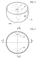
- the reference number 1 designates as a whole a cylinder of a known type for storing a fluid at high pressure.
- the cylinder 1 is of the type commonly used as fuel tank of a motor vehicle for containing methane gas at a pressure ranging between approximately 200 bar and approximately 300 bar, necessary for supplying an internal-combustion engine.
- the cylinder 1 has a body 2 having a bottom portion 3, an intermediate portion 4, and a head portion 5.
- the bottom portion 3 has a substantially flattened shape
- the intermediate portion 4 has a generally hollow cylindrical shape
- the head portion 5 has a substantially hemispherical or cap-like shape.
- the shape illustrated in Figure 1 is the one typical of the case where the body 2 is obtained in a single piece, via hot pressing of a steel billet or a thick steel plate, to form first of all the portions 3 and 4.
- the portion 5 is then obtained via fluoforming by deforming an end part of the intermediate portion 4.
- the intermediate portion 4 of the body 2 can be obtained starting from a tube, in which case both of the ends of the latter are shaped like a hemispherical cap via fluoforming.
- the reference number 6 designates a valve, made in a way in itself known and provided to enable both charging of the cylinder 1 with methane gas, in the case of refuelling, and drawing of the gas from the cylinder in order to supply the engine of the motor vehicle.
- the valve 6 is connected to suitable pipes for charging and drawing-off of the gas (not represented).
- a threaded part of the former is screwed in a through hole provided with internal screw on the top of the head portion 5.
- valve 6 projects from the body 2, in a position aligned with the axis of the latter. Said arrangement derives from the need to position the valve 6 in a point where the thickness of the body 2 is large, to be able to provide therein a sufficiently long threaded through hole such as to guarantee a secure anchorage of the valve 6.
- the process of fluoforming used for providing the head part 5 enables a sufficiently thick area of anchorage of the valve 6 for said purpose to be obtained.
- Such an embodiment presents the drawback that, on account of said technique of formation of the body 2, the valve 6 can be located only in a position corresponding to the top of the portion 5, to project from the latter. This has adverse effects on the overall dimensions of the cylinder 1 since the valve 6 must, for normative reasons, be kept at a certain distance from possible surfaces of impact. Consequently, the useful space that can be occupied by the body 2 is smaller, a fact that jeopardizes its capacity for storage of gas.
- the degree of safety and the storage capacity of the tank are increased by a particular modelling of the body of the cylinder, and in particular of one of its ends, in order to make available the respective valve in a safer or more protected position.
- the end of the body of the cylinder to which the respective valve is fixed is not modelled via fluoforming.
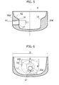
- Figures 2 to 6 represent a possible embodiment of a tank for storing fluids at operating pressures higher than 100 bar according to the present invention, said body being formed starting from a single piece, and being provided, in a position corresponding to a terminal region thereof - herein conventionally defined as "head region" -, with portions with thickened walls arranged with central symmetry with respect to the axis of the body, made in at least one of which is the hole in which the valve is fixed.
- the tank according to the invention designated as a whole by 11, has a body 12, in which an intermediate hollow region, designated by 14, and two terminal regions 13 and 15 are identified, which form the bottom and the head of the body 12, respectively.
- the intermediate region 14 is substantially cylindrical in shape, whilst the bottom terminal region 13 is as a whole cup-shaped; in particular, it has the shape of a hemispherical cap.
- the head region 15 has, instead, a more flattened configuration.
- the body 12 is made of hardened and tempered steels with high equivalent carbon content having ultimate strengths comprised between 800 and 1200 MPa (such as, for instance chromium-manganese or chromium-molybdenum steels, or high-strength steels, for example, 34CrMo4).
- the valve 6 is fixed to the head terminal region 15 in a lateral position, said possibility of positioning being allowed on account of a particular conformation of the region itself.
- FIG. 3 Visible in Figure 3 is the internal part of just the terminal region 15, and represented in Figures 4, 5 and 6 are cross-sectional views of the same region, respectively according to three different mutually orthogonal planes. It should be noted that in said figures, for greater clarity, the representation of the valve 6 has been omitted.
- the portions 16 are of dimensions such as to enable formation of an internal thread 17, or other type of through hole, in the desired position and of the desired length. Screwed into said hole is the threaded fixing part of the valve 6 of Figure 2, the remaining connection part of the valve remaining, instead, on the outside of the body 12.
- a first area 16a defines a substantially plane seat, which is made in a position corresponding to the hole 17 and has maximum thickness, with reference to a direction orthogonal to the central axis X of the body 12.
- a second area 16b defines a first area of radiusing around the aforesaid first area 16a
- a third area 16c defines a second area of radiusing around the aforesaid first and second areas 16a, 16b.
- the area 16c extends, on one side, towards the intermediate region 14 and, on the opposite side, towards the end of the terminal region 15, radiusing thereto in a continuous way.
- the first and second radiusing areas, respectively of the second and third areas 16b, 16c have curvatures of opposite sign.
- the external side of the latter has, in a position corresponding to the first area 16a, a corresponding plane external region 16a'.
- first, second and third areas 16a, 16b and 16c have characteristic dimensions that define globally a specific geometry thereof. Said dimensions are listed hereinafter:
- the minimum side of the first area 16a must be greater than the diameter of the hole 17, preferably at least approximately 7% - 8% greater than the aforesaid diameter. In the case where, for example, the hole 17 has a diameter of 26 mm, the minimum side will be approximately 28 mm.
- the body 12 of the tank or cylinder according to the present invention can be obtained in a simple and fast way via pressing from a steel billet of the type previously referred to, in so far as said technology is well suited to the complexity of the profile of the portions 16.
- the embodiments according to the invention previously described enable improvement of the functionality of tanks that are to contain gas at high pressure, at operating pressures higher than 100 bar, on account of the possibility of placing the valve 6 in positions that have a positive impact both on the safety - in so far as the valve is more protected in the case of impact - and on the capacity for storage of fuel in the presence of an increase in exploitable volume for housing the tank body.
- Figures 13A and 13B illustrate, respectively, the case of housing in said boot of a tank 11 according to the embodiment of Figure 2, and of a tank 1 according to the known art appearing in Figure 1.
- L designates the maximum axial or longitudinal dimensions of the two tanks.
- the longitudinal encumbrance of the tank 11 appearing in Figure 13A may be greater than that of the tank 1 appearing in Figure 13B thanks to the different position of the valve 6.
- valve 6 can be positioned in areas of the bodies that are in any case safe.
- valve 6 envisaged according to the invention is strictly linked to the conformation of the body 12 and in particular to the presence of the thickened portions 16.
- the portions 16 lead to a strengthening of the side area of the head terminal region 15 so as to enable formation of the hole 17 for fixing the valve 6.
- the present invention also envisages the possible presence of more than two portions with thickened walls 16, with the condition that they are arranged with central symmetry with respect to the axis X of the body 12 so as to distribute the circumferential stresses evenly over the cross sections of the body 12.
- the body 12 of the tank 11 is obtained starting from a single piece, in this case a billet of high-alloy steel.
- Figure 7 illustrates a step of pre-forming in which the billet, designated by 20, is compressed under a press 21 for the purpose of obtaining a pre-form.
- a first step of forging is carried out, illustrated in Figure 8, in which the pre-form is inserted in a die 22 and pressed by a counter-die 23 to obtain a form 20b having a longitudinal cross section with a substantially cup-shaped profile, the bottom end of which will define the head terminal region 15 of the body 12.
- a second forging step is carried out that envisages the use of a second counter-die 23', visible in Figure 9.
- the counter-die 23' has two surface cavities 23b' diametrally opposite with respect to a central axis of the die and counter-die, and defining the matrix of the thickened portions 16.
- the cavities 23b have a first area, a second area, and a third area, corresponding, respectively, to the first, second and third areas of the thickened portions 16.
- the aforesaid areas of the counter-die are characterized by dimensions corresponding to those defined for the portions 16, which, in the case of the embodiment described above, are linked to one another according to the relations given previously.
- a form 20c is obtained, which defines, at the bottom (as viewed in Figure 10), the head terminal region 15 provided laterally with the thickened portions 16.
- the form 20c is drawn and coined so as to make a form 20d provided also with the hollow intermediate region 14.
- the part of the form 20c that extends, at the top, to the thickened portions 16 is plastically deformed under the action of forces impressed by rollers 24 that stretch the aforesaid part.
- the form 20c is thus lengthened until a volume substantially equal to that of the body 12 of the tank 11 is obtained.
- the form 20d obtained by drawing undergoes a process of sand-blasting, which consists in smoothing the walls with a jet of sand and water under pressure.
- the drawn product, represented by the form 20d is checked dimensionally and via visual inspection to detect the presence of possible irregularities of the structure that might be capable of impairing the mechanical properties of the finished tank.
- the form 20d is closed via the formation of the bottom region 13 according to modalities in themselves known.
- said step envisages setting in rotation the form 20d, which is heated in a position corresponding to its open end and on which a roller 25 acts in such a way as to curve the wall 20d' defining said end in order to form the hemispherical cap that distinguishes the bottom terminal region 13.
- one of the portions 16 is perforated and, the hole 17 made is threaded internally for the purpose of receiving the threaded stem of the valve 6.
- valves for one and the same cylinder, for example the one for charging the fluid and the other for drawing it off.
- Each of said valves would be located in a position corresponding to a respective portion 16 provided with a threaded hole 17, as previously described, the two valves projecting, then, from the two opposite sides of one and the same head terminal region 15.
- the invention has been described with particular reference to the construction of tanks or cylinders for application in the automobile sector, but it is clear that it may also be used in any other field that presents the same specific problems, in particular ones due to the need to guarantee an adequate mechanical sturdiness at operating pressures higher than 100 bar.
- the tanks outlined previously has been described with reference to the storage of methane gas, it is clear that they are to be understood as being suitable for storing any other fluid at operating pressures higher than 100 bar, and in particular substantially comprised between 200 and 300 bar.
Landscapes
- Engineering & Computer Science (AREA)
- Mechanical Engineering (AREA)
- General Engineering & Computer Science (AREA)
- Filling Or Discharging Of Gas Storage Vessels (AREA)
Priority Applications (5)
| Application Number | Priority Date | Filing Date | Title |
|---|---|---|---|
| DE602006004368T DE602006004368D1 (de) | 2006-11-24 | 2006-11-24 | Behälter zum Lagern von Flüssigkeiten unter Hochdruck, insbesondere eines Gases zum Betanken eines Kraftfahrzeugmotors und Verfahren zu seiner Herstellung |
| AT06425803T ATE418041T1 (de) | 2006-11-24 | 2006-11-24 | Behälter zum lagern von flüssigkeiten unter hochdruck, insbesondere eines gases zum betanken eines kraftfahrzeugmotors und verfahren zu seiner herstellung |
| EP06425803A EP1925873B1 (de) | 2006-11-24 | 2006-11-24 | Behälter zum Lagern von Flüssigkeiten unter Hochdruck, insbesondere eines Gases zum Betanken eines Kraftfahrzeugmotors und Verfahren zu seiner Herstellung |
| PCT/IB2007/002337 WO2008062261A1 (en) | 2006-11-24 | 2007-08-07 | Tank for storing fluids at high pressures, in particular a gas for fuelling a motor vehicle engine, and manufacturing method thereof |
| CN200780010199.4A CN101405536B (zh) | 2006-11-24 | 2007-08-07 | 用于存储尤其是为机动车辆发动机提供燃料的气体的高压流体的罐及其制造方法 |
Applications Claiming Priority (1)
| Application Number | Priority Date | Filing Date | Title |
|---|---|---|---|
| EP06425803A EP1925873B1 (de) | 2006-11-24 | 2006-11-24 | Behälter zum Lagern von Flüssigkeiten unter Hochdruck, insbesondere eines Gases zum Betanken eines Kraftfahrzeugmotors und Verfahren zu seiner Herstellung |
Publications (2)
| Publication Number | Publication Date |
|---|---|
| EP1925873A1 true EP1925873A1 (de) | 2008-05-28 |
| EP1925873B1 EP1925873B1 (de) | 2008-12-17 |
Family
ID=37989172
Family Applications (1)
| Application Number | Title | Priority Date | Filing Date |
|---|---|---|---|
| EP06425803A Not-in-force EP1925873B1 (de) | 2006-11-24 | 2006-11-24 | Behälter zum Lagern von Flüssigkeiten unter Hochdruck, insbesondere eines Gases zum Betanken eines Kraftfahrzeugmotors und Verfahren zu seiner Herstellung |
Country Status (5)
| Country | Link |
|---|---|
| EP (1) | EP1925873B1 (de) |
| CN (1) | CN101405536B (de) |
| AT (1) | ATE418041T1 (de) |
| DE (1) | DE602006004368D1 (de) |
| WO (1) | WO2008062261A1 (de) |
Citations (4)
| Publication number | Priority date | Publication date | Assignee | Title |
|---|---|---|---|---|
| GB482142A (en) * | 1936-10-10 | 1938-03-24 | Harold Dickinson Brunton | Improvements in and relating to containers for fluids under pressure |
| GB1558409A (en) * | 1977-10-06 | 1980-01-03 | Boc Ltd | Fluid storage vessels |
| WO1999047850A2 (de) * | 1998-03-18 | 1999-09-23 | Mannesmann Ag | Vorrichtung zum speichern von druckgas |
| US20030006349A1 (en) * | 2001-05-04 | 2003-01-09 | Sadowski Mark M. M. | Pressure vessel mounting system |
Family Cites Families (2)
| Publication number | Priority date | Publication date | Assignee | Title |
|---|---|---|---|---|
| US8056928B2 (en) * | 2004-10-29 | 2011-11-15 | Ford Global Technologies, Llc | Vehicle and fuel storage system for a vehicle |
| CN100402916C (zh) * | 2005-12-02 | 2008-07-16 | 马磊 | 压缩天然气汽车换瓶加气法及装置 |
-
2006
- 2006-11-24 EP EP06425803A patent/EP1925873B1/de not_active Not-in-force
- 2006-11-24 AT AT06425803T patent/ATE418041T1/de not_active IP Right Cessation
- 2006-11-24 DE DE602006004368T patent/DE602006004368D1/de active Active
-
2007
- 2007-08-07 CN CN200780010199.4A patent/CN101405536B/zh not_active Expired - Fee Related
- 2007-08-07 WO PCT/IB2007/002337 patent/WO2008062261A1/en not_active Ceased
Patent Citations (4)
| Publication number | Priority date | Publication date | Assignee | Title |
|---|---|---|---|---|
| GB482142A (en) * | 1936-10-10 | 1938-03-24 | Harold Dickinson Brunton | Improvements in and relating to containers for fluids under pressure |
| GB1558409A (en) * | 1977-10-06 | 1980-01-03 | Boc Ltd | Fluid storage vessels |
| WO1999047850A2 (de) * | 1998-03-18 | 1999-09-23 | Mannesmann Ag | Vorrichtung zum speichern von druckgas |
| US20030006349A1 (en) * | 2001-05-04 | 2003-01-09 | Sadowski Mark M. M. | Pressure vessel mounting system |
Also Published As
| Publication number | Publication date |
|---|---|
| ATE418041T1 (de) | 2009-01-15 |
| WO2008062261A1 (en) | 2008-05-29 |
| CN101405536A (zh) | 2009-04-08 |
| EP1925873B1 (de) | 2008-12-17 |
| DE602006004368D1 (de) | 2009-01-29 |
| CN101405536B (zh) | 2011-06-08 |
Similar Documents
| Publication | Publication Date | Title |
|---|---|---|
| US8794478B2 (en) | Method for producing a pressure tank, a pressure tank and a pressure tank group | |
| US20050011891A1 (en) | Compressed gas tank for a motor vehicle | |
| US20240369184A1 (en) | Pressure Vessel, Pressure Vessel System, Motor Vehicle and Method for Forming Ribs | |
| EP4067724B1 (de) | Hochdrucktank, der eine ringschicht und eine darauf gewickelte schraubenförmige schicht aufweist, und hestellungsverfahren dafür | |
| CN109838682B (zh) | 一种35MPa铝合金内胆全缠绕玄武岩纤维的压缩天然气瓶 | |
| EP2293919B1 (de) | Verfahren zur herstellung eines speicherbehälters | |
| KR20140021066A (ko) | 고압 가스 용기 및 고압 가스 용기의 제조 방법 | |
| RU2675173C2 (ru) | Усовершенствованный способ изготовления высокопрочных композиционных сосудов с внутренним металлическим лейнером и сосуды, изготовленные упомянутым способом | |
| CN104075101A (zh) | 用于储存压缩天然气的罐 | |
| US20220196207A1 (en) | Method for Producing a Barrier Layer of a Pressure Vessel, and Pressure Vessel | |
| ITMI20012390A1 (it) | Accumulatore ad alta pressione per combustibile per un sistema di iniezione del combustibile per motori endotermici | |
| EP1925873B1 (de) | Behälter zum Lagern von Flüssigkeiten unter Hochdruck, insbesondere eines Gases zum Betanken eines Kraftfahrzeugmotors und Verfahren zu seiner Herstellung | |
| Yahashi et al. | Development of high-pressure hydrogen storage system for new FCV | |
| WO1997009561A1 (en) | Dual chamber fluid storage vessel | |
| CN216591027U (zh) | 一种大直径不锈钢焊接内胆碳纤维全缠绕瓶式容器 | |
| DE102007017425A1 (de) | Gaskraftstofftank für Kraftfahrzeug | |
| US20250305632A1 (en) | Method for producing a pressure vessel | |
| KR102901551B1 (ko) | 나사 형성 강관 및 그 제조 방법 | |
| CN214306464U (zh) | 一种车载储氢瓶阀座结构 | |
| William et al. | Finite element analysis of composite over-wrapped pressure vessels for hydrogen storage | |
| EP1422013A1 (de) | Behälter zur Lagerung von Fluiden unter einem Arbeitsdruck von mehr als 100 bar, insbesondere von Gas für Fahrzeugmotoren sowie ensprechendes Herstellungsverfahren. | |
| JP4084573B2 (ja) | 圧力容器鏡部のラップ部成形方法 | |
| US12025274B2 (en) | Tank device for storing a gaseous medium and method for producing a tank device | |
| RU2018452C1 (ru) | Автомобильный баллон для сжиженного газа | |
| CN2402907Y (zh) | 新型车用压缩天然气高压气瓶 |
Legal Events
| Date | Code | Title | Description |
|---|---|---|---|
| PUAI | Public reference made under article 153(3) epc to a published international application that has entered the european phase |
Free format text: ORIGINAL CODE: 0009012 |
|
| 17P | Request for examination filed |
Effective date: 20070803 |
|
| AK | Designated contracting states |
Kind code of ref document: A1 Designated state(s): AT BE BG CH CY CZ DE DK EE ES FI FR GB GR HU IE IS IT LI LT LU LV MC NL PL PT RO SE SI SK TR |
|
| AX | Request for extension of the european patent |
Extension state: AL BA HR MK RS |
|
| GRAP | Despatch of communication of intention to grant a patent |
Free format text: ORIGINAL CODE: EPIDOSNIGR1 |
|
| GRAS | Grant fee paid |
Free format text: ORIGINAL CODE: EPIDOSNIGR3 |
|
| GRAA | (expected) grant |
Free format text: ORIGINAL CODE: 0009210 |
|
| AK | Designated contracting states |
Kind code of ref document: B1 Designated state(s): AT BE BG CH CY CZ DE DK EE ES FI FR GB GR HU IE IS IT LI LT LU LV MC NL PL PT RO SE SI SK TR |
|
| REG | Reference to a national code |
Ref country code: GB Ref legal event code: FG4D |
|
| REG | Reference to a national code |
Ref country code: CH Ref legal event code: EP |
|
| REG | Reference to a national code |
Ref country code: IE Ref legal event code: FG4D |
|
| REF | Corresponds to: |
Ref document number: 602006004368 Country of ref document: DE Date of ref document: 20090129 Kind code of ref document: P |
|
| AKX | Designation fees paid |
Designated state(s): AT BE BG CH CY CZ DE DK EE ES FI FR GB GR HU IE IS IT LI LT LU LV MC NL PL PT RO SE SI SK TR |
|
| PG25 | Lapsed in a contracting state [announced via postgrant information from national office to epo] |
Ref country code: LT Free format text: LAPSE BECAUSE OF FAILURE TO SUBMIT A TRANSLATION OF THE DESCRIPTION OR TO PAY THE FEE WITHIN THE PRESCRIBED TIME-LIMIT Effective date: 20081217 |
|
| PG25 | Lapsed in a contracting state [announced via postgrant information from national office to epo] |
Ref country code: NL Free format text: LAPSE BECAUSE OF FAILURE TO SUBMIT A TRANSLATION OF THE DESCRIPTION OR TO PAY THE FEE WITHIN THE PRESCRIBED TIME-LIMIT Effective date: 20081217 Ref country code: PL Free format text: LAPSE BECAUSE OF FAILURE TO SUBMIT A TRANSLATION OF THE DESCRIPTION OR TO PAY THE FEE WITHIN THE PRESCRIBED TIME-LIMIT Effective date: 20081217 Ref country code: SI Free format text: LAPSE BECAUSE OF FAILURE TO SUBMIT A TRANSLATION OF THE DESCRIPTION OR TO PAY THE FEE WITHIN THE PRESCRIBED TIME-LIMIT Effective date: 20081217 Ref country code: FI Free format text: LAPSE BECAUSE OF FAILURE TO SUBMIT A TRANSLATION OF THE DESCRIPTION OR TO PAY THE FEE WITHIN THE PRESCRIBED TIME-LIMIT Effective date: 20081217 Ref country code: LV Free format text: LAPSE BECAUSE OF FAILURE TO SUBMIT A TRANSLATION OF THE DESCRIPTION OR TO PAY THE FEE WITHIN THE PRESCRIBED TIME-LIMIT Effective date: 20081217 |
|
| NLV1 | Nl: lapsed or annulled due to failure to fulfill the requirements of art. 29p and 29m of the patents act | ||
| PG25 | Lapsed in a contracting state [announced via postgrant information from national office to epo] |
Ref country code: EE Free format text: LAPSE BECAUSE OF FAILURE TO SUBMIT A TRANSLATION OF THE DESCRIPTION OR TO PAY THE FEE WITHIN THE PRESCRIBED TIME-LIMIT Effective date: 20081217 Ref country code: RO Free format text: LAPSE BECAUSE OF FAILURE TO SUBMIT A TRANSLATION OF THE DESCRIPTION OR TO PAY THE FEE WITHIN THE PRESCRIBED TIME-LIMIT Effective date: 20081217 Ref country code: BE Free format text: LAPSE BECAUSE OF FAILURE TO SUBMIT A TRANSLATION OF THE DESCRIPTION OR TO PAY THE FEE WITHIN THE PRESCRIBED TIME-LIMIT Effective date: 20081217 Ref country code: BG Free format text: LAPSE BECAUSE OF FAILURE TO SUBMIT A TRANSLATION OF THE DESCRIPTION OR TO PAY THE FEE WITHIN THE PRESCRIBED TIME-LIMIT Effective date: 20090317 Ref country code: ES Free format text: LAPSE BECAUSE OF FAILURE TO SUBMIT A TRANSLATION OF THE DESCRIPTION OR TO PAY THE FEE WITHIN THE PRESCRIBED TIME-LIMIT Effective date: 20090328 |
|
| PG25 | Lapsed in a contracting state [announced via postgrant information from national office to epo] |
Ref country code: IS Free format text: LAPSE BECAUSE OF FAILURE TO SUBMIT A TRANSLATION OF THE DESCRIPTION OR TO PAY THE FEE WITHIN THE PRESCRIBED TIME-LIMIT Effective date: 20090417 Ref country code: CZ Free format text: LAPSE BECAUSE OF FAILURE TO SUBMIT A TRANSLATION OF THE DESCRIPTION OR TO PAY THE FEE WITHIN THE PRESCRIBED TIME-LIMIT Effective date: 20081217 Ref country code: AT Free format text: LAPSE BECAUSE OF FAILURE TO SUBMIT A TRANSLATION OF THE DESCRIPTION OR TO PAY THE FEE WITHIN THE PRESCRIBED TIME-LIMIT Effective date: 20081217 Ref country code: SE Free format text: LAPSE BECAUSE OF FAILURE TO SUBMIT A TRANSLATION OF THE DESCRIPTION OR TO PAY THE FEE WITHIN THE PRESCRIBED TIME-LIMIT Effective date: 20090317 Ref country code: PT Free format text: LAPSE BECAUSE OF FAILURE TO SUBMIT A TRANSLATION OF THE DESCRIPTION OR TO PAY THE FEE WITHIN THE PRESCRIBED TIME-LIMIT Effective date: 20090518 |
|
| PG25 | Lapsed in a contracting state [announced via postgrant information from national office to epo] |
Ref country code: SK Free format text: LAPSE BECAUSE OF FAILURE TO SUBMIT A TRANSLATION OF THE DESCRIPTION OR TO PAY THE FEE WITHIN THE PRESCRIBED TIME-LIMIT Effective date: 20081217 |
|
| PLBE | No opposition filed within time limit |
Free format text: ORIGINAL CODE: 0009261 |
|
| STAA | Information on the status of an ep patent application or granted ep patent |
Free format text: STATUS: NO OPPOSITION FILED WITHIN TIME LIMIT |
|
| PG25 | Lapsed in a contracting state [announced via postgrant information from national office to epo] |
Ref country code: DK Free format text: LAPSE BECAUSE OF FAILURE TO SUBMIT A TRANSLATION OF THE DESCRIPTION OR TO PAY THE FEE WITHIN THE PRESCRIBED TIME-LIMIT Effective date: 20081217 |
|
| 26N | No opposition filed |
Effective date: 20090918 |
|
| PG25 | Lapsed in a contracting state [announced via postgrant information from national office to epo] |
Ref country code: MC Free format text: LAPSE BECAUSE OF NON-PAYMENT OF DUE FEES Effective date: 20091130 |
|
| PG25 | Lapsed in a contracting state [announced via postgrant information from national office to epo] |
Ref country code: IE Free format text: LAPSE BECAUSE OF NON-PAYMENT OF DUE FEES Effective date: 20091124 Ref country code: GR Free format text: LAPSE BECAUSE OF FAILURE TO SUBMIT A TRANSLATION OF THE DESCRIPTION OR TO PAY THE FEE WITHIN THE PRESCRIBED TIME-LIMIT Effective date: 20090318 |
|
| PG25 | Lapsed in a contracting state [announced via postgrant information from national office to epo] |
Ref country code: LU Free format text: LAPSE BECAUSE OF NON-PAYMENT OF DUE FEES Effective date: 20091124 |
|
| PG25 | Lapsed in a contracting state [announced via postgrant information from national office to epo] |
Ref country code: HU Free format text: LAPSE BECAUSE OF FAILURE TO SUBMIT A TRANSLATION OF THE DESCRIPTION OR TO PAY THE FEE WITHIN THE PRESCRIBED TIME-LIMIT Effective date: 20090618 |
|
| REG | Reference to a national code |
Ref country code: CH Ref legal event code: PL |
|
| GBPC | Gb: european patent ceased through non-payment of renewal fee |
Effective date: 20101124 |
|
| PG25 | Lapsed in a contracting state [announced via postgrant information from national office to epo] |
Ref country code: LI Free format text: LAPSE BECAUSE OF NON-PAYMENT OF DUE FEES Effective date: 20101130 Ref country code: CH Free format text: LAPSE BECAUSE OF NON-PAYMENT OF DUE FEES Effective date: 20101130 |
|
| PG25 | Lapsed in a contracting state [announced via postgrant information from national office to epo] |
Ref country code: TR Free format text: LAPSE BECAUSE OF FAILURE TO SUBMIT A TRANSLATION OF THE DESCRIPTION OR TO PAY THE FEE WITHIN THE PRESCRIBED TIME-LIMIT Effective date: 20081217 |
|
| PG25 | Lapsed in a contracting state [announced via postgrant information from national office to epo] |
Ref country code: CY Free format text: LAPSE BECAUSE OF FAILURE TO SUBMIT A TRANSLATION OF THE DESCRIPTION OR TO PAY THE FEE WITHIN THE PRESCRIBED TIME-LIMIT Effective date: 20081217 |
|
| PG25 | Lapsed in a contracting state [announced via postgrant information from national office to epo] |
Ref country code: GB Free format text: LAPSE BECAUSE OF NON-PAYMENT OF DUE FEES Effective date: 20101124 |
|
| REG | Reference to a national code |
Ref country code: FR Ref legal event code: PLFP Year of fee payment: 10 |
|
| REG | Reference to a national code |
Ref country code: FR Ref legal event code: PLFP Year of fee payment: 11 |
|
| PGFP | Annual fee paid to national office [announced via postgrant information from national office to epo] |
Ref country code: FR Payment date: 20161129 Year of fee payment: 11 |
|
| PGFP | Annual fee paid to national office [announced via postgrant information from national office to epo] |
Ref country code: IT Payment date: 20161125 Year of fee payment: 11 |
|
| PGFP | Annual fee paid to national office [announced via postgrant information from national office to epo] |
Ref country code: DE Payment date: 20170131 Year of fee payment: 11 |
|
| REG | Reference to a national code |
Ref country code: DE Ref legal event code: R119 Ref document number: 602006004368 Country of ref document: DE |
|
| REG | Reference to a national code |
Ref country code: FR Ref legal event code: ST Effective date: 20180731 |
|
| PG25 | Lapsed in a contracting state [announced via postgrant information from national office to epo] |
Ref country code: IT Free format text: LAPSE BECAUSE OF NON-PAYMENT OF DUE FEES Effective date: 20171124 Ref country code: DE Free format text: LAPSE BECAUSE OF NON-PAYMENT OF DUE FEES Effective date: 20180602 Ref country code: FR Free format text: LAPSE BECAUSE OF NON-PAYMENT OF DUE FEES Effective date: 20171130 |