EP1925882A1 - Burner - Google Patents
Burner Download PDFInfo
- Publication number
- EP1925882A1 EP1925882A1 EP06124537A EP06124537A EP1925882A1 EP 1925882 A1 EP1925882 A1 EP 1925882A1 EP 06124537 A EP06124537 A EP 06124537A EP 06124537 A EP06124537 A EP 06124537A EP 1925882 A1 EP1925882 A1 EP 1925882A1
- Authority
- EP
- European Patent Office
- Prior art keywords
- front part
- fan house
- connecting surface
- fan
- burner
- Prior art date
- Legal status (The legal status is an assumption and is not a legal conclusion. Google has not performed a legal analysis and makes no representation as to the accuracy of the status listed.)
- Withdrawn
Links
Images
Classifications
-
- F—MECHANICAL ENGINEERING; LIGHTING; HEATING; WEAPONS; BLASTING
- F23—COMBUSTION APPARATUS; COMBUSTION PROCESSES
- F23D—BURNERS
- F23D11/00—Burners using a direct spraying action of liquid droplets or vaporised liquid into the combustion space
- F23D11/001—Spraying nozzle combined with forced draft fan in one unit
-
- F—MECHANICAL ENGINEERING; LIGHTING; HEATING; WEAPONS; BLASTING
- F23—COMBUSTION APPARATUS; COMBUSTION PROCESSES
- F23D—BURNERS
- F23D14/00—Burners for combustion of a gas, e.g. of a gas stored under pressure as a liquid
- F23D14/34—Burners specially adapted for use with means for pressurising the gaseous fuel or the combustion air
- F23D14/36—Burners specially adapted for use with means for pressurising the gaseous fuel or the combustion air in which the compressor and burner form a single unit
Definitions
- the present invention relates to a burner comprising a fan house, in which a fan wheel is located, a burner tube, to which burner tube oxygen can be blown by means of the fan wheel, and a front part detachably connecting the burner tube to the fan house.
- Burners are utilized for producing thermal heat by combusting a fuel, such as oil, natural gas, biogas, wood pellets, etc., in the presence of oxygen.
- a fuel such as oil, natural gas, biogas, wood pellets, etc.
- An fan supplies oxygen, often in the form of ambient air, to a burner tube.
- a fuel nozzle supplies the fuel, such as oil or a combustible gas, to the burner tube and atomizes the fuel such that the fuel becomes mixed with the oxygen. Combustion of the fuel in the presence of the oxygen is initiated by means of electrodes.
- US 6,488,496 in the name of Hauck Manufacturing Co. illustrates a burner which can operate with different types of fuel.
- a problem with this burner is that it is not easy to perform maintenance work on the burner, since many internal parts of the burner are difficult to access.
- maintaining the burner described in US 6,488,496 is a time consuming process, which means that the burner will be out of operation for a considerable time, each time the burner has to be stopped for maintenance.
- An object of the present invention is to provide a burner of such a design that the interior parts of the burner are easily accessible, such that maintenance of the burner can be made quickly.
- a burner comprising a fan house, in which a fan wheel is located, a burner tube, to which burner tube oxygen can be blown by means of the fan wheel, and a front part detachably connecting the burner tube to the fan house, the burner being characterised in that the front part has a circumferential front part connecting surface, which surrounds a front part opening adapted for allowing oxygen supplied by the fan wheel to enter the burner tube, the fan house having a circumferential fan house connecting surface surrounding a fan house opening and being adapted for cooperating with said front part connecting surface with said front part connecting surface lying close to said fan house connecting surface, the circumferential front part connecting surface having an angle of 125 to 145° to a centre line of the burner tube.
- An advantage of this burner is that it becomes very easy to access the interior parts of the fan house, since the abovementioned angle provides for a very large fan house opening in the fan house. Furthermore, the flow pattern of an oxygen containing gas, such as air, that is blown by the fan wheel is not deteriorated by this type of burner.
- a further advantage is that ancillary equipment, such as a fuel supply pipe, can be fastened to the fan house without interfering with the front part or with the burner tube. According to a still more preferred embodiment said angle is 130 to 140°.
- the circumferential front part connecting surface is provided with interlocking portions, being adapted for co-operating with corresponding interlocking portions provided on the circumferential fan house connecting surface.
- interlocking portions provide for stable and safe connection of the front part to the fan house, in such a manner that the fan house obtains the correct mounting position on the front part, and that the fan house can be quickly detached from the front part for maintenance.
- a rotatable bolt is mounted on the fan house for urging the interlocking portions of the circumferential front part connecting surface into engagement with the interlocking portions of the circumferential fan house connecting surface.
- An advantage of this embodiment is that it provides for simple and safe mounting of the fan house on the front part. A single bolt is sufficient for mounting the fan house to the front part in such a manner that no gas leaks out between the fan house and the front part.
- a fuel supply device is fixed to the fan house, such that said fuel supply device remains fastened to the fan house when the fan house is detached from said front part.
- An advantage of this embodiment is that the fuel supply device can remain fastened to the fan house when the latter is removed from the front part for service. This makes service of the fuel supply device easier.
- the fan house comprises a first portion in which the fan wheel is located, and a second portion which is adapted for allowing an oxygen containing gas forwarded by the fan wheel to expand and form a desired flow pattern, the circumferential fan house connecting surface being substantially parallel to the axis of rotation of the fan wheel and extending from a first point, which is adjacent to the transition between said first portion and said second portion, to a second point which is located on a surface of said second portion being remote from said first portion.
- a distance from a free terminal end of the burner tube to said first point is shorter than a distance from said free terminal end of the burner tube to said second point.
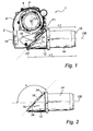
- Fig. 1 illustrates a burner 1.
- the burner 1 has a fan house 2 to which a motor 4 is attached.
- the motor 4 is adapted to drive a fan wheel 6, which is also shown in Fig. 4.
- the centre axis CA of the fan wheel 6 coincides with the centre axis of the motor 4.
- the fan wheel 6 is located in a first portion 8 of the fan house 2, which first portion 8 is the upper portion of the fan house 2 as seen in Fig. 1.
- the fan wheel 6 is adapted for producing a flow of a gas containing oxygen, normally this gas is air, which flow is to be forwarded to a second portion 10 of the fan house 2, which second portion 10 is the lower portion of the fan house 2 as seen in Fig. 1. In the second portion 10 a desired gas flow pattern is established.
- EP 1 022 470 B1 A preferred alternative of how such a gas flow pattern could appear is shown in EP 1 022 470 B1 .
- a fan house As is illustrated in Fig. 1 of EP 1 022 470 B1 a fan house is preferably provided with a surrounding wall of such a shape that a desired air pressure is achieved.
- a front part 12 is detachably mounted to the fan house 2.
- the front part 12 is adapted for forwarding the flow of gas from the fan house 2 to a cylindrical burner tube 14.
- the burner tube 14 is adapted for being mounted in a boiler, not shown. Inside the burner tube 14 the flow of gas is mixed with a fuel, such as oil or gas, resulting in the combustion of the fuel in the presence of the oxygen of the gas.
- the fan house 2 When performing maintenance work on the burner 1 the fan house 2 is detached from the front part 12 and the burner tube 14. It is normally preferred to leave the burner tube 14 and the front part 12 in place in the boiler while maintaining the fan house 2.
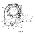
- Fig. 2 illustrates the burner tube 14 and the front part 12 after the fan house 2 has been detached there from.
- the front part 12 has a circumferential front part connecting surface 16 which surrounds a front part opening 18.
- the front part opening 18 is adapted for allowing the gas from the fan house 2 to enter the interior of the front part 12, which generally has the shape of an open cylinder, such that the gas can be forwarded through the front part 12 to the burner tube 14.
- the circumferential front part connecting surface 16 has an angle ⁇ of 135° to a centre line CB of the burner tube 14, which centre line CB substantially coincides also with the centre line of the cylindrical front part 12.
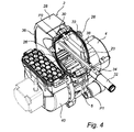
- Fig. 3 illustrates the fan house 2 after it has been detached from the front part 12.
- the fan house 2 has a circumferential fan house connecting surface 20 which surrounds a fan house opening 22.
- the circumferential fan house connecting surface 20, which is also shown in Fig. 4, is adapted for cooperating with said circumferential front part connecting surface 16 in such a manner that said front part connecting surface 16 lies close to said fan house connecting surface 20 to form a sealed connection, as it is illustrated in Fig. 1 of the present application.
- the circumferential front part connecting surface 16 is provided with interlocking portions 24 that are adapted for co-operating with corresponding interlocking portions 26 provided on the circumferential fan house connecting surface 20, which are illustrated in Fig. 3 and Fig. 4.
- Fig. 3 furthermore illustrates that the circumferential fan house connecting surface 20 is substantially parallel to the axis of rotation CA of the fan wheel 6.
- the fan house connecting surface 20 extends, as seen in Fig. 3, from a first point P1, which is located adjacent to the transition between the first portion 8 and the second portion 10 of the fan house 2, to a second point P2 which is located on a surface 28 of said second portion 10, which surface 28 is remote from said first portion 8.
- the surface 28 of the second portion 10 of the fan house 2 is opposite to the first portion 8.
- the fan house connecting surface 20 extends from the point P1 and in a direction away from the burner tube 14 towards the point P2. Consequently, a distance L1, parallel to the centre line CB of the burner tube 14, from a free terminal end 15 of the burner tube 14 to the point P1 will be shorter than a distance L2, parallel to the centre line CB, from the free terminal end 15 of the burner tube 14 to the point P2, as shown in Fig. 1 of the present application.
- a bolt 30 is rotatably mounted to the surface 28.
- the bolt 30 is adapted for urging the interlocking portions 24 of the circumferential front part connecting surface 16 into engagement with the interlocking portions 26 of the circumferential fan house connecting surface 20, thereby providing for a firm attachment, still detachable, between the fan house 2 and the front part 12.
- a fuel supply device comprises a fuel nozzle, such as an oil nozzle 32, and a fuel supply pipe 34, to which the oil nozzle 32 is fastened.
- the fuel supply pipe 34 is mounted on a back side 36 of the second portion 10 of the fan house 2.
- a photocell 38 which is adapted for supervision of a flame in the burner tube 14, is also mounted to the back side 36.
- Fig. 4 illustrates the fan house 2 after it has been detached from the front part 12.
- the fan house 2 has, as it is shown in Fig. 4, been turned around for the purpose of facilitating maintenance of a gas intake 40 attached to the fan house 2, and in particular for facilitating maintenance of the fan wheel 6, the fuel nozzle 32, the photocell 38 and the interior of the fan house 2.
- the fan house opening 22, which is encircled by the circumferential fan house connecting surface 20, has a generally elliptic shape, which makes it larger compared to a circular opening obtained in the prior art, as represented by US 6,488,496 .
- the large elliptic fan house opening 22 provides for easier access to the interior of the fan house 2, since it becomes easier to insert a human hand, and/or instruments through such a fan house opening 22. Furthermore, it is clear from Fig. 4 that the fan house opening 22 opens very much towards the fan wheel 6. This is thanks to the fact that the circumferential front part connecting surface 16 has an angle ⁇ of 135° to the centre line CB of the burner tube 14, the circumferential fan house connecting surface 20 having a complementary angle, such that the fan wheel 6 can be accessed almost from above, as shown in Fig. 4.
- the angle, ⁇ , between the circumferential front part connecting surface 16 and the centre line CB of the burner tube 14 is 135°.
- This angle can varied between certain limits.
- the angle ⁇ is not less than 125°.
- An angle ⁇ of less than 125° would not provide the desired good access to the fan wheel 6 and to the interior of the fan house 2.
- the angle ⁇ is not more than 145°.
- An angle ⁇ of more than 145° would mean that the second point P2 would be located very close to the back side 36 of the fan house 2. Such a location might deteriorate the desired flow pattern of the gas, since the flow pattern is, at such a point, still very sensitive to disturbances, which may be caused at the joint between the fan house 2 and the front part 12.
- the angle, ⁇ , between the circumferential front part connecting surface 16 and the centre line CB of the burner tube 14 is preferably in the range of 125° to 145°, more preferably in the range of 130° to 140°.
- the burner tube 14 and the front part 12 have a circular cross-section. It will be appreciated that other cross-sections are also possible.
- the burner tube and the front part could have a square, ellipsoidal, or hexagonal cross-section.
Landscapes
- Engineering & Computer Science (AREA)
- Chemical & Material Sciences (AREA)
- Combustion & Propulsion (AREA)
- Mechanical Engineering (AREA)
- General Engineering & Computer Science (AREA)
- Air Supply (AREA)
Abstract
A burner (1) comprises a fan house (2), a burner tube (14), and a front part (12) detachably connecting the burner tube (14) to the fan house (2). The front part (12) has a circumferential front part connecting surface (16), which surrounds a front part opening (18) adapted for allowing oxygen to enter the burner tube (14). The fan house (2) has a fan house connecting surface (20) surrounding a fan house opening (22) and being adapted for cooperating with said front part connecting surface (16) with said front part connecting surface (16) lying close to said fan house connecting surface (22). The circumferential front part connecting surface (16) has an angle (α) of 125 to 145° to a centre line (CB) of the burner tube (14) .
Description
- The present invention relates to a burner comprising a fan house, in which a fan wheel is located, a burner tube, to which burner tube oxygen can be blown by means of the fan wheel, and a front part detachably connecting the burner tube to the fan house.
- Burners are utilized for producing thermal heat by combusting a fuel, such as oil, natural gas, biogas, wood pellets, etc., in the presence of oxygen. An fan supplies oxygen, often in the form of ambient air, to a burner tube. A fuel nozzle supplies the fuel, such as oil or a combustible gas, to the burner tube and atomizes the fuel such that the fuel becomes mixed with the oxygen. Combustion of the fuel in the presence of the oxygen is initiated by means of electrodes.
-
US 6,488,496 in the name of Hauck Manufacturing Co., illustrates a burner which can operate with different types of fuel. A problem with this burner is that it is not easy to perform maintenance work on the burner, since many internal parts of the burner are difficult to access. Thus, maintaining the burner described inUS 6,488,496 is a time consuming process, which means that the burner will be out of operation for a considerable time, each time the burner has to be stopped for maintenance. - An object of the present invention is to provide a burner of such a design that the interior parts of the burner are easily accessible, such that maintenance of the burner can be made quickly.
- This object is achieved by a burner comprising a fan house, in which a fan wheel is located, a burner tube, to which burner tube oxygen can be blown by means of the fan wheel, and a front part detachably connecting the burner tube to the fan house, the burner being characterised in that the front part has a circumferential front part connecting surface, which surrounds a front part opening adapted for allowing oxygen supplied by the fan wheel to enter the burner tube, the fan house having a circumferential fan house connecting surface surrounding a fan house opening and being adapted for cooperating with said front part connecting surface with said front part connecting surface lying close to said fan house connecting surface, the circumferential front part connecting surface having an angle of 125 to 145° to a centre line of the burner tube.
- An advantage of this burner is that it becomes very easy to access the interior parts of the fan house, since the abovementioned angle provides for a very large fan house opening in the fan house. Furthermore, the flow pattern of an oxygen containing gas, such as air, that is blown by the fan wheel is not deteriorated by this type of burner. A further advantage is that ancillary equipment, such as a fuel supply pipe, can be fastened to the fan house without interfering with the front part or with the burner tube. According to a still more preferred embodiment said angle is 130 to 140°.
- According to a preferred embodiment the circumferential front part connecting surface is provided with interlocking portions, being adapted for co-operating with corresponding interlocking portions provided on the circumferential fan house connecting surface. An advantage of the interlocking portions is that they provide for stable and safe connection of the front part to the fan house, in such a manner that the fan house obtains the correct mounting position on the front part, and that the fan house can be quickly detached from the front part for maintenance. Still more preferably, a rotatable bolt is mounted on the fan house for urging the interlocking portions of the circumferential front part connecting surface into engagement with the interlocking portions of the circumferential fan house connecting surface. An advantage of this embodiment is that it provides for simple and safe mounting of the fan house on the front part. A single bolt is sufficient for mounting the fan house to the front part in such a manner that no gas leaks out between the fan house and the front part.
- Preferably a fuel supply device is fixed to the fan house, such that said fuel supply device remains fastened to the fan house when the fan house is detached from said front part. An advantage of this embodiment is that the fuel supply device can remain fastened to the fan house when the latter is removed from the front part for service. This makes service of the fuel supply device easier.
- According to a preferred embodiment the fan house comprises a first portion in which the fan wheel is located, and a second portion which is adapted for allowing an oxygen containing gas forwarded by the fan wheel to expand and form a desired flow pattern, the circumferential fan house connecting surface being substantially parallel to the axis of rotation of the fan wheel and extending from a first point, which is adjacent to the transition between said first portion and said second portion, to a second point which is located on a surface of said second portion being remote from said first portion. An advantage of this embodiment is that it provides for superior access to the interior parts of the fan house, including the fan wheel, without disturbing the flow pattern of the oxygen containing gas supplied by the fan wheel. Still more preferably a distance from a free terminal end of the burner tube to said first point is shorter than a distance from said free terminal end of the burner tube to said second point. By this design the fan house opening opens directly towards the fan wheel, such that maintenance of the fan wheel becomes easier.
- Further objects and features of the present invention will be apparent from the description and the claims.
- The invention will now be described in more detail with reference to the appended drawings in which:
- Fig. 1 is a schematic side view and illustrates a burner having a fan house, a front part, and a burner tube.
- Fig. 2 is a schematic side view and illustrates the front part and the burner tube.
- Fig. 3 is a schematic side view and illustrates the fan house.
- Fig. 4 is a three-dimensional view and illustrates the fan house and a fan house opening.
- Fig. 1 illustrates a
burner 1. Theburner 1 has afan house 2 to which amotor 4 is attached. Themotor 4 is adapted to drive afan wheel 6, which is also shown in Fig. 4. The centre axis CA of thefan wheel 6 coincides with the centre axis of themotor 4. Thefan wheel 6 is located in afirst portion 8 of thefan house 2, whichfirst portion 8 is the upper portion of thefan house 2 as seen in Fig. 1. Thefan wheel 6 is adapted for producing a flow of a gas containing oxygen, normally this gas is air, which flow is to be forwarded to asecond portion 10 of thefan house 2, whichsecond portion 10 is the lower portion of thefan house 2 as seen in Fig. 1. In the second portion 10 a desired gas flow pattern is established. A preferred alternative of how such a gas flow pattern could appear is shown inEP 1 022 470 B1EP 1 022 470 B1 - Referring again to Fig. 1 of the present application a
front part 12 is detachably mounted to thefan house 2. Thefront part 12 is adapted for forwarding the flow of gas from thefan house 2 to acylindrical burner tube 14. Theburner tube 14 is adapted for being mounted in a boiler, not shown. Inside theburner tube 14 the flow of gas is mixed with a fuel, such as oil or gas, resulting in the combustion of the fuel in the presence of the oxygen of the gas. - When performing maintenance work on the
burner 1 thefan house 2 is detached from thefront part 12 and theburner tube 14. It is normally preferred to leave theburner tube 14 and thefront part 12 in place in the boiler while maintaining thefan house 2. - Fig. 2 illustrates the
burner tube 14 and thefront part 12 after thefan house 2 has been detached there from. Thefront part 12 has a circumferential frontpart connecting surface 16 which surrounds a front part opening 18. The front part opening 18 is adapted for allowing the gas from thefan house 2 to enter the interior of thefront part 12, which generally has the shape of an open cylinder, such that the gas can be forwarded through thefront part 12 to theburner tube 14. The circumferential frontpart connecting surface 16 has an angle α of 135° to a centre line CB of theburner tube 14, which centre line CB substantially coincides also with the centre line of thecylindrical front part 12. - Fig. 3 illustrates the
fan house 2 after it has been detached from thefront part 12. Thefan house 2 has a circumferential fanhouse connecting surface 20 which surrounds a fan house opening 22. The circumferential fanhouse connecting surface 20, which is also shown in Fig. 4, is adapted for cooperating with said circumferential frontpart connecting surface 16 in such a manner that said frontpart connecting surface 16 lies close to said fanhouse connecting surface 20 to form a sealed connection, as it is illustrated in Fig. 1 of the present application. Returning to Fig. 2, it can be seen that the circumferential frontpart connecting surface 16 is provided with interlockingportions 24 that are adapted for co-operating with corresponding interlockingportions 26 provided on the circumferential fanhouse connecting surface 20, which are illustrated in Fig. 3 and Fig. 4. - Fig. 3 furthermore illustrates that the circumferential fan
house connecting surface 20 is substantially parallel to the axis of rotation CA of thefan wheel 6. By this is meant that the plane of the circumferential fanhouse connecting surface 20 does not intersect with the centre axis CA of thefan wheel 6. The fanhouse connecting surface 20 extends, as seen in Fig. 3, from a first point P1, which is located adjacent to the transition between thefirst portion 8 and thesecond portion 10 of thefan house 2, to a second point P2 which is located on asurface 28 of saidsecond portion 10, whichsurface 28 is remote from saidfirst portion 8. In fact, thesurface 28 of thesecond portion 10 of thefan house 2 is opposite to thefirst portion 8. Hence, the fanhouse connecting surface 20 extends from the point P1 and in a direction away from theburner tube 14 towards the point P2. Consequently, a distance L1, parallel to the centre line CB of theburner tube 14, from a freeterminal end 15 of theburner tube 14 to the point P1 will be shorter than a distance L2, parallel to the centre line CB, from the freeterminal end 15 of theburner tube 14 to the point P2, as shown in Fig. 1 of the present application. Returning to Fig. 3, abolt 30 is rotatably mounted to thesurface 28. Thebolt 30 is adapted for urging the interlockingportions 24 of the circumferential frontpart connecting surface 16 into engagement with the interlockingportions 26 of the circumferential fanhouse connecting surface 20, thereby providing for a firm attachment, still detachable, between thefan house 2 and thefront part 12. - A fuel supply device comprises a fuel nozzle, such as an
oil nozzle 32, and afuel supply pipe 34, to which theoil nozzle 32 is fastened. Thefuel supply pipe 34 is mounted on aback side 36 of thesecond portion 10 of thefan house 2. Aphotocell 38, which is adapted for supervision of a flame in theburner tube 14, is also mounted to theback side 36. When thefan house 2 is detached from thefront part 12 and theburner tube 14, which normally remain fastened to the boiler, thefuel supply pipe 34 and thephotocell 38 being mounted to theback side 36 of thefan house 2 will follow thefan house 2. This fact facilitates the maintenance of thefuel nozzle 32, thefuel supply pipe 34, and thephotocell 38. - Fig. 4 illustrates the
fan house 2 after it has been detached from thefront part 12. Thefan house 2 has, as it is shown in Fig. 4, been turned around for the purpose of facilitating maintenance of agas intake 40 attached to thefan house 2, and in particular for facilitating maintenance of thefan wheel 6, thefuel nozzle 32, thephotocell 38 and the interior of thefan house 2. As can be seen in Fig. 4, thefan house opening 22, which is encircled by the circumferential fanhouse connecting surface 20, has a generally elliptic shape, which makes it larger compared to a circular opening obtained in the prior art, as represented byUS 6,488,496 . The large ellipticfan house opening 22 provides for easier access to the interior of thefan house 2, since it becomes easier to insert a human hand, and/or instruments through such afan house opening 22. Furthermore, it is clear from Fig. 4 that thefan house opening 22 opens very much towards thefan wheel 6. This is thanks to the fact that the circumferential frontpart connecting surface 16 has an angle α of 135° to the centre line CB of theburner tube 14, the circumferential fanhouse connecting surface 20 having a complementary angle, such that thefan wheel 6 can be accessed almost from above, as shown in Fig. 4. - It will be appreciated that numerous variants of the above described embodiments are possible within the scope of the appended claims.
- Above it has been described that the angle, α, between the circumferential front
part connecting surface 16 and the centre line CB of theburner tube 14 is 135°. This angle can varied between certain limits. Preferably the angle α is not less than 125°. An angle α of less than 125° would not provide the desired good access to thefan wheel 6 and to the interior of thefan house 2. Preferably the angle α is not more than 145°. An angle α of more than 145° would mean that the second point P2 would be located very close to theback side 36 of thefan house 2. Such a location might deteriorate the desired flow pattern of the gas, since the flow pattern is, at such a point, still very sensitive to disturbances, which may be caused at the joint between thefan house 2 and thefront part 12. Furthermore, such a location of the second point P2 might interfere with thefuel supply pipe 34 and thephotocell 38, such that those components would have to be fastened to thefront part 12 instead of to thefan house 2, and, consequently, thefuel supply pipe 34 and thephotocell 38 would remain fastened to thefront part 12 and, thus, normally to the boiler, when thefan house 2 is removed fromfront part 12. This would make maintenance of thefuel supply pipe 34 and of thephotocell 38 more difficult. Thus, the angle, α, between the circumferential frontpart connecting surface 16 and the centre line CB of theburner tube 14 is preferably in the range of 125° to 145°, more preferably in the range of 130° to 140°. - Above it has been described that the
burner tube 14 and thefront part 12 have a circular cross-section. It will be appreciated that other cross-sections are also possible. For example, the burner tube and the front part could have a square, ellipsoidal, or hexagonal cross-section.
Claims (7)
- A burner comprising a fan house (2), in which a fan wheel (6) is located, a burner tube (14), to which burner tube (14) oxygen can be blown by means of the fan wheel (6), and a front part (12) detachably connecting the burner tube (14) to the fan house (2),
characterised in that the front part (12) has a circumferential front part connecting surface (16), which surrounds a front part opening (18) adapted for allowing oxygen supplied by the fan wheel (6) to enter the burner tube (14), the fan house (2) having a circumferential fan house connecting surface (20) surrounding a fan house opening (22) and being adapted for cooperating with said front part connecting surface (16) with said front part connecting surface (16) lying close to said fan house connecting surface (22), the circumferential front part connecting surface (16) having an angle (α) of 125° to 145° to a centre line (CB) of the burner tube (14). - A burner according to claim 1, wherein said angle (α) between the circumferential front part connecting surface (16) and the centre line (CB) of the burner tube (14) is 130° to 140°.
- A burner according to any one of claims 1-2, wherein the circumferential front part connecting surface (16) is provided with interlocking portions (24), being adapted for co-operating with corresponding interlocking portions (26) provided on the circumferential fan house connecting surface (20).
- A burner according to claim 3, wherein a rotatable bolt (30) is mounted on the fan house (2) for urging the interlocking portions (24) of the circumferential front part connecting surface (16) into engagement with the interlocking portions (26) of the circumferential fan house connecting surface (20).
- A burner according to any one of claims 1-4, wherein a fuel supply device (32, 34) is fixed to the fan house (2), such that said fuel supply device (32, 34) remains fastened to the fan house (2) when the fan house (2) is detached from said front part (12).
- A burner according to any one of claims 1-5, wherein the fan house (2) comprises a first portion (8) in which the fan wheel (6) is located, and a second portion (10) which is adapted for allowing an oxygen containing gas forwarded by the fan wheel (6) to expand and form a desired flow pattern, the circumferential fan house connecting surface (20) being substantially parallel to the axis (CA) of rotation of the fan wheel (6) and extending from a first point (P1), which is adjacent to the transition between said first portion (8) and said second portion (10), to a second point (P2) located on a surface (28) of said second portion (10) being remote from said first portion (8).
- A burner according to claim 6, wherein a distance (L1) from a free terminal end (15) of the burner tube (14) to said first point (P1) is shorter than a distance (L2) from said free terminal end (15) of the burner tube (14) to said second point (P2).
Priority Applications (1)
| Application Number | Priority Date | Filing Date | Title |
|---|---|---|---|
| EP06124537A EP1925882A1 (en) | 2006-11-22 | 2006-11-22 | Burner |
Applications Claiming Priority (1)
| Application Number | Priority Date | Filing Date | Title |
|---|---|---|---|
| EP06124537A EP1925882A1 (en) | 2006-11-22 | 2006-11-22 | Burner |
Publications (1)
| Publication Number | Publication Date |
|---|---|
| EP1925882A1 true EP1925882A1 (en) | 2008-05-28 |
Family
ID=37896151
Family Applications (1)
| Application Number | Title | Priority Date | Filing Date |
|---|---|---|---|
| EP06124537A Withdrawn EP1925882A1 (en) | 2006-11-22 | 2006-11-22 | Burner |
Country Status (1)
| Country | Link |
|---|---|
| EP (1) | EP1925882A1 (en) |
Cited By (1)
| Publication number | Priority date | Publication date | Assignee | Title |
|---|---|---|---|---|
| EP2792950A1 (en) * | 2013-04-17 | 2014-10-22 | Guillot Industrie | Burner with coupling member |
Citations (4)
| Publication number | Priority date | Publication date | Assignee | Title |
|---|---|---|---|---|
| NL299566A (en) * | ||||
| FR949132A (en) * | 1947-06-27 | 1949-08-22 | Bruleurs Thermex Soc D | Burners improvements |
| DE1973489U (en) * | 1967-07-08 | 1967-11-30 | Landwehr & Schultz G M B H | LIGHT OIL BURNER. |
| EP1582809A2 (en) * | 2004-03-30 | 2005-10-05 | Compagnie Europeenne de Bruleurs S.A. | Forced-draft burner comprising a ventilation box inclined with respect to the combustion head |
-
2006
- 2006-11-22 EP EP06124537A patent/EP1925882A1/en not_active Withdrawn
Patent Citations (4)
| Publication number | Priority date | Publication date | Assignee | Title |
|---|---|---|---|---|
| NL299566A (en) * | ||||
| FR949132A (en) * | 1947-06-27 | 1949-08-22 | Bruleurs Thermex Soc D | Burners improvements |
| DE1973489U (en) * | 1967-07-08 | 1967-11-30 | Landwehr & Schultz G M B H | LIGHT OIL BURNER. |
| EP1582809A2 (en) * | 2004-03-30 | 2005-10-05 | Compagnie Europeenne de Bruleurs S.A. | Forced-draft burner comprising a ventilation box inclined with respect to the combustion head |
Cited By (2)
| Publication number | Priority date | Publication date | Assignee | Title |
|---|---|---|---|---|
| EP2792950A1 (en) * | 2013-04-17 | 2014-10-22 | Guillot Industrie | Burner with coupling member |
| FR3004789A1 (en) * | 2013-04-17 | 2014-10-24 | Guillot Ind Sa | BURNER WITH CONNECTING MEMBER |
Similar Documents
| Publication | Publication Date | Title |
|---|---|---|
| US6468072B2 (en) | Wind guard for open flame gas lantern | |
| DE60201562D1 (en) | Torch with ultra-stable pilot burner and process | |
| EP1930661A2 (en) | Folding camping stove | |
| CN112377901A (en) | Combustion head of air and gas premixing combustor of condensing boiler and premixing combustion method thereof | |
| CN213599364U (en) | Combustion head of air and gas premixing combustor of condensation boiler | |
| CA2684542C (en) | Draught-resistant fireplace pilot | |
| CN201289081Y (en) | Stove burner with improved center cap | |
| US20090032013A1 (en) | Preformed fireplace capable of venting vertically or horizontally | |
| CN206268004U (en) | A kind of igniter of universal petrol engine | |
| US20110104621A1 (en) | Draught-resistant fireplace pilot | |
| CN218635149U (en) | Combustion mechanism of steam sprayer and steam sprayer | |
| JP2017198378A (en) | Boiler | |
| CN219571917U (en) | Gas burner | |
| KR20130125427A (en) | Stove pipe connecting structure of intake and exhaust pipe for boiler | |
| JP4937416B1 (en) | Stove for cassette cylinder | |
| CN102042481B (en) | Full-automatic compulsory gasification machine for bottled liquefied petroleum gas | |
| JP2004169971A (en) | Combustion plate burner with oxygen deficiency detecting burner | |
| CN220017696U (en) | Wall-mounted intelligent water heater | |
| JP7575671B2 (en) | Combustion equipment and hot water equipment | |
| CN211781995U (en) | gas water heater | |
| CN202955692U (en) | Alcohol-based fuel gasification combustion burner | |
| CN209540867U (en) | Facilitate the burner upper bellows of installation | |
| KR20000019302A (en) | Boiler | |
| KR200372040Y1 (en) | a exhaust cap for gas boiler exhaust pipe | |
| CN209540868U (en) | Can allow air and return the well-mixed burner upper bellows of cigarette |
Legal Events
| Date | Code | Title | Description |
|---|---|---|---|
| PUAI | Public reference made under article 153(3) epc to a published international application that has entered the european phase |
Free format text: ORIGINAL CODE: 0009012 |
|
| AK | Designated contracting states |
Kind code of ref document: A1 Designated state(s): AT BE BG CH CY CZ DE DK EE ES FI FR GB GR HU IE IS IT LI LT LU LV MC NL PL PT RO SE SI SK TR |
|
| AX | Request for extension of the european patent |
Extension state: AL BA HR MK RS |
|
| AKX | Designation fees paid | ||
| REG | Reference to a national code |
Ref country code: DE Ref legal event code: 8566 |
|
| STAA | Information on the status of an ep patent application or granted ep patent |
Free format text: STATUS: THE APPLICATION IS DEEMED TO BE WITHDRAWN |
|
| 18D | Application deemed to be withdrawn |
Effective date: 20081129 |