EP1925885B1 - Garniture creuse, four avec une garniture creuse et procédé pour son opération - Google Patents
Garniture creuse, four avec une garniture creuse et procédé pour son opération Download PDFInfo
- Publication number
- EP1925885B1 EP1925885B1 EP06024497A EP06024497A EP1925885B1 EP 1925885 B1 EP1925885 B1 EP 1925885B1 EP 06024497 A EP06024497 A EP 06024497A EP 06024497 A EP06024497 A EP 06024497A EP 1925885 B1 EP1925885 B1 EP 1925885B1
- Authority
- EP
- European Patent Office
- Prior art keywords
- accessory
- cooking
- heat
- food
- fluid
- Prior art date
- Legal status (The legal status is an assumption and is not a legal conclusion. Google has not performed a legal analysis and makes no representation as to the accuracy of the status listed.)
- Not-in-force
Links
- 238000010411 cooking Methods 0.000 title claims abstract description 113
- 238000011017 operating method Methods 0.000 title 1
- 239000012530 fluid Substances 0.000 claims abstract description 24
- 238000011068 loading method Methods 0.000 claims abstract description 19
- 238000003780 insertion Methods 0.000 claims description 18
- 230000037431 insertion Effects 0.000 claims description 18
- 239000011248 coating agent Substances 0.000 claims description 15
- 238000000576 coating method Methods 0.000 claims description 15
- 238000005338 heat storage Methods 0.000 claims description 14
- 230000005855 radiation Effects 0.000 claims description 14
- 238000000034 method Methods 0.000 claims description 10
- 230000008878 coupling Effects 0.000 claims description 8
- 238000010168 coupling process Methods 0.000 claims description 8
- 238000005859 coupling reaction Methods 0.000 claims description 8
- 238000010438 heat treatment Methods 0.000 claims description 7
- 230000001105 regulatory effect Effects 0.000 claims description 7
- XLYOFNOQVPJJNP-UHFFFAOYSA-N water Substances O XLYOFNOQVPJJNP-UHFFFAOYSA-N 0.000 claims description 4
- 229910000838 Al alloy Inorganic materials 0.000 claims description 3
- 239000006260 foam Substances 0.000 claims description 2
- 238000005259 measurement Methods 0.000 claims 5
- 239000004809 Teflon Substances 0.000 claims 1
- 229920006362 Teflon® Polymers 0.000 claims 1
- 238000001704 evaporation Methods 0.000 claims 1
- 239000001995 intermetallic alloy Substances 0.000 claims 1
- 150000004812 organic fluorine compounds Chemical class 0.000 claims 1
- 239000004020 conductor Substances 0.000 description 5
- 238000009826 distribution Methods 0.000 description 3
- 239000007788 liquid Substances 0.000 description 3
- 239000000463 material Substances 0.000 description 3
- 238000009833 condensation Methods 0.000 description 2
- 230000005494 condensation Effects 0.000 description 2
- 238000007599 discharging Methods 0.000 description 2
- 230000000694 effects Effects 0.000 description 2
- 239000007789 gas Substances 0.000 description 2
- 238000010025 steaming Methods 0.000 description 2
- 238000010521 absorption reaction Methods 0.000 description 1
- XAGFODPZIPBFFR-UHFFFAOYSA-N aluminium Chemical compound [Al] XAGFODPZIPBFFR-UHFFFAOYSA-N 0.000 description 1
- 229910052782 aluminium Inorganic materials 0.000 description 1
- 239000012876 carrier material Substances 0.000 description 1
- 239000000919 ceramic Substances 0.000 description 1
- 238000006243 chemical reaction Methods 0.000 description 1
- 239000000567 combustion gas Substances 0.000 description 1
- 238000010276 construction Methods 0.000 description 1
- 230000001276 controlling effect Effects 0.000 description 1
- 238000001816 cooling Methods 0.000 description 1
- 238000005265 energy consumption Methods 0.000 description 1
- 238000004146 energy storage Methods 0.000 description 1
- 238000005516 engineering process Methods 0.000 description 1
- 238000000605 extraction Methods 0.000 description 1
- 230000006870 function Effects 0.000 description 1
- 239000011521 glass Substances 0.000 description 1
- 238000004519 manufacturing process Methods 0.000 description 1
- 239000004033 plastic Substances 0.000 description 1
- 229920003023 plastic Polymers 0.000 description 1
- 238000002360 preparation method Methods 0.000 description 1
- 238000005086 pumping Methods 0.000 description 1
- 230000000284 resting effect Effects 0.000 description 1
- 239000004449 solid propellant Substances 0.000 description 1
- 238000009423 ventilation Methods 0.000 description 1
- 238000010792 warming Methods 0.000 description 1
Images


Classifications
-
- F—MECHANICAL ENGINEERING; LIGHTING; HEATING; WEAPONS; BLASTING
- F24—HEATING; RANGES; VENTILATING
- F24C—DOMESTIC STOVES OR RANGES ; DETAILS OF DOMESTIC STOVES OR RANGES, OF GENERAL APPLICATION
- F24C15/00—Details
- F24C15/16—Shelves, racks or trays inside ovens; Supports therefor
-
- F—MECHANICAL ENGINEERING; LIGHTING; HEATING; WEAPONS; BLASTING
- F24—HEATING; RANGES; VENTILATING
- F24C—DOMESTIC STOVES OR RANGES ; DETAILS OF DOMESTIC STOVES OR RANGES, OF GENERAL APPLICATION
- F24C15/00—Details
- F24C15/32—Arrangements of ducts for hot gases, e.g. in or around baking ovens
- F24C15/322—Arrangements of ducts for hot gases, e.g. in or around baking ovens with forced circulation
Definitions
- the invention relates to an accessory according to the preamble of claim 1, a cooking appliance with a cooking chamber, in which such an accessory can be introduced or introduced; and a method of operating such a cooking appliance.
- Cooking utensils for thermal food preparation are well known in the art. Thermal radiation and / or heat conduction are used to transfer heat. Thermal radiation is mainly used in the use of so-called top and bottom heat. In this case, one or more walls of a cooking chamber, for example. Via heating wires brought to an elevated temperature, so that they emit heat radiation. This heat radiation then hits on food and is at least partially absorbed by it, thereby increasing the temperature of the food.
- the energy transfer by heat conduction is of central importance in a hot air operation, steaming and / or grilling of food. When grilling, the food is placed directly on a hot plate or a hot grill. Due to the interstices of the grill can of course also heat radiation for heating the food penetrate through.
- the typical grill patterns come about through contact of the food with a hot carrier material, namely the grill grate.
- a hot carrier material namely the grill grate.
- water condenses on the food to be cooked, thus transferring the condensation heat of the water to the food in addition to the thermal energy of the water gas molecules.
- energy becomes a hot cooking chamber atmosphere transferred to the food.
- the various media for transferring heat to food such as by steam, heat radiation or heat conduction, are usually heated electrically or by burning a liquid or solid fuel.
- Garages with heat accumulators improve the energy input substantially, but must ensure a uniform and rapid distribution of hot air in the oven so as not to cause a negative effect on the food, such as in the form of uneven browning, burned areas or the like.
- a cooking appliance with an energy storage and energy extraction system serves to provide the cooking appliance with very large amounts of energy in the short term, without making very high connection performance of the cooking appliance necessary.
- Energy can be stored for this purpose in the form of thermal, electrical and / or mechanical energy in a heat storage, the charging can be done in times where little or no energy is needed for the heating of the cooking appliance.
- thermal heat energy contained in the cooking space is at least partially transferred to the heat storage and stored there.
- a heater but also a circulation system, a humidity control, a steam generator and / or a cooling unit can be operated, with a measuring and control system is used, with the right dosage of energy and the right one Time to use the energy can be ensured.
- a cooking appliance thus additionally serves to reduce energy consumption.
- a cooking appliance with an electrically heatable heat storage through which an air flow for heating a cooking chamber one or more times can be passed.
- the heat storage channels for this purpose passing channels open into the oven and can be closed by flaps. By closing the flaps, the entry of heat energy from the heat storage can be prevented.
- a disadvantage of this prior art that only hot air from the heat storage is supplied to the cooking chamber. The heat energy from the memory is thus transferred to the food only by convection via the cooking chamber atmosphere.
- the JP 2002 071 138 discloses a cooking appliance in which steam from a steam generator is passed through a high temperature heat storage tank to produce superheated steam. With the help of the heat accumulator so steam is generated, which can condense on food. The disadvantage of this is that the heat can be used to heat the same only by condensation of the steam on the food. Also, a targeted admission of individual levels in the oven is not possible.
- the EP 0 002 784 A1 discloses a H exertluftgarêt, in which a uniform loading of a cooking food to be cooked with hot air is realized in that the flow direction of the circulating air is changed during cooking with a suitable device.
- From the DE 102 20 266 A1 is a support structure for receiving food known, with a large number of food items can be cooked per shelf level. Due to the support structure ensures that the various items to be cooked as closely as possible but still spaced from each other can be introduced into the cooking chamber, so that the circulated in the cooking hot air heats the food on all sides and evenly with heat energy.
- a cooking appliance with a generic accessory comprising a pipe system for the even distribution of steam in a cooking chamber, is from the EP 1 538 396 A1 known.
- the pipe system has a plurality of openings and is connected to a steam generator, so that the steam from the steam generator flows through the pipe system and at the various locations in the cooking chamber distributed from the pipe system exits. This ensures that cooked food placed in the cooking appliance can be supplied with steam uniformly and on all sides. At the same time, a hot air circulation in the cooking chamber can be provided.
- Object of the present invention is to further develop the generic accessories such that in the simplest possible but also variable manner, an energy input in various forms in a food, preferably in different loading levels of the accessories, allows, without causing high costs.
- a cooking appliance with a cooking chamber in which an inventive accessory can be introduced or introduced, supplied with claim 11.
- the invention also relates to a method for operating a cooking appliance according to the invention according to claim 25.
- FIG. 1 shows an inventive accessory in the form of a so-called tray rack 1 for a cooking appliance
- the plug-in ladders 10 may be formed as tubes, perpendicular to which slide rails 20 are mounted, which may be formed, for example, as part-tubes.
- the tubes of the plug-in ladders 10 have openings 30 for supplying a hot air flow and openings 40 for discharging the hot air flow and thus act as air-conducting tubes.
- inserts 50 can be introduced, each having at least one cavity (not shown).
- the cavities in the interior of the inserts 50 are connected to openings 60, which allow entry of air into the slots 50.
- the openings 60 of the inserts 50 can be connected via the tubes of the insertion conductors 10 with the openings 30, namely via openings not shown in the slide rails 20.
- the openings 60 of the inserts 50 may be suitable even for receiving an air flow. Especially suitable in the latter case are funnel-shaped, closable openings, as in FIG FIG. 1 indicated on the left.
- FIG. 1 Is the tray rack 1 according to the invention FIG. 1 in a hot air stream which impinges on the rack frame 1 from the left side, a portion of the hot air flows will enter the openings 30 and / or 60 and from there flow through the interior of the inserts 50.
- the hot air flow can give off part of its thermal energy to the materials from which the inserts 50 are made.
- the at least partially cooled air can then escape through the openings 40 and / or 70 from the rack frame 1, that is, the cooking chamber atmosphere to be supplied again.
- the openings 40 on the in FIG. 1 The right side of the insertion ladders 10 can be used alternatively or cumulatively for introducing the air flow, wherein in the latter case the insertion ladders 10 or the inserts 50 must have further openings which are suitable for directing the air flow from the cavities of the tray rack 1.
- any other gaseous or liquid medium can also be used. If the following is an air flow, the use of a general fluid flow is always possible.
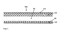
- FIG. 2 shows the cross section of a first inventive insert 50a for the in FIG. 1 shown tray rack 1, with an air gap 80 for passing a hot air flow.
- the underside of the insert 50a forms a poorly heat-conducting layer 90, while the top is made up of a good heat-conducting layer 100.
- a highly thermally conductive material from which the good heat conducting layer 100 may be made is an aluminum alloy capable of passing the thermal energy from the interior of the insert 50a to a food (not shown) located on the top of the food Insert 50a is placed.
- the poorly thermally conductive layer 90 on the underside of the insert 50a according to the invention ensures that the heat is not conducted through the underside as much as possible.
- ceramics and plastics which are only partially suitable for use in a cooking appliance due to lack of robustness, lack of temperature resistance or high manufacturing costs, especially foams or multilayer systems come as material for the poor thermal conductivity layer 90 in question.
- a non-stick coating 110 on the top of a non-stick coating 110 and on the bottom of a coating 120, which hinders thermal heat radiation from the bottom of the insert 50a ago, are provided.
- drawer 50a As well as for all other drawer variants according to the invention, it does not matter whether it has a grid structure, a completely flat structure or another structure, as long as there are continuous openings for an air flow inside.
- a slot 50a is adapted to dissipate heat of a hot air stream flowing therethrough, especially upwards.
- This is one such insert 50a suitable for roasting not shown Gargut when the food is placed directly on top of the same.
- the heat transfer is then given above all by the contact heat of the surface of the insert 50a according to the invention.
- a further layer may also be provided on the upper side of the good heat-conducting layer 100, which layer is well suited for emitting heat radiation in the temperature range used.
- Such a so-called black radiator in contrast to the poorly heat radiating coating 120 on the underside of the insert 50a according to the invention would lead to a high emission of heat radiation on the top.
- a food placed on a grid (not shown) above the tray 50a can be grilled by the heat radiation.
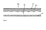
- FIG. 3 shows a second insert 50b according to the invention, which in its construction corresponds to that of FIG. 2 similar.
- the insert 50b has an air gap 80 which is delimited on the one hand by a poorly heat-conducting layer 91 and on the other hand by a good heat-conducting layer 101, a non-stick coating 111 being applied to the latter.
- the insert 50b has, on the one hand, a structure of the surface of the good heat-conducting layer 101 on the side facing the air gap 80, and, on the other hand, no poorly heat-radiating coating is provided on the poorly heat-conducting layer 91.
- connecting webs may also be provided in the interior of the air gap, which serve both to improve the heat conduction and to stabilize the structure.
- connecting webs may also be provided in the interior of the air gap, which serve both to improve the heat conduction and to stabilize the structure.
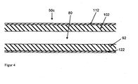
- FIG. 4 shows the cross section of a third inventive insert 50c for generating top and bottom heat.
- both a lower layer 92 and an upper layer 102 which delimit an air gap 80, are made of a good heat-conducting material.
- both the lower layer 92 and the upper layer 102 on the side of the air gap 80 may be provided with a structure (not shown) as shown in FIG FIG. 3 is shown.
- a non-stick coating 112 may be applied to the good heat-conducting layer 102.
- the food can be cooked from above by top heat from the top drawer 50c and bottom by contact heat by resting on the bottom drawer 50c or bottom heat when placing the food on an additional grill (not shown) ) or the like between the shelves 50c are cooked.
- FIG. 5 shows a cross section of a fourth inventive insert 50d for generating top heat.
- the underside consists of a good heat-conducting layer 93, which may be coated with a good heat-radiating material (not shown).
- the upper side consists of a poorly heat-conducting layer 103, on which a poorly heat-radiating layer 113 can be applied.
- the various bays 50a, 50b, 50c, 50d or other bays 50 according to the invention mixed into the slide rails 20 of a tray rack 1 according to the invention.
- a first food to be cooked on a top drawer 50c with contact heat, baked on a subjacent drawer 50a, a second food with top and bottom heat and under a next, underlying drawer 50d a third food only with top heat are applied.
- a variety of other combinations and possibilities are conceivable.
- FIG. 6 shows a cooking appliance 130 with a cooking chamber 140 and a door 150 in a horizontal section.
- an insertion head 10 In the cooking chamber 140 is an insertion head 10 according to the invention with openings 30 for introducing a hot air flow.
- a radial fan 160 To generate the hot air flow is a radial fan 160 which is driven by an engine (not shown) via an axis and is surrounded annularly by a heater 170 in the form of heating coils.
- the radial fan 160 attracts air from the center of the cooking chamber 140 at the height of the axis through a central opening 181 of an air guide plate 180 and accelerates it radially outward, in FIG. 6 up and down.
- a flow is also generated, which is blown along the edge of the cooking chamber 140 along.
- the air flow in the cooking chamber 140 is led into the openings 30 of the insertion ladders 10 according to the invention, driven by the radial fan 160 to get into slots (not shown), as with respect to the FIGS. 2 to 5 can be described described.
- openings not shown then finally leaves the at least partially cooled in the slots air the same and can be reheated by sucking on the radial fan 160 and passing the heater 170 to be used for further heating of the bays and thus not shown food to the same.
- FIG. 7 shows a vertical cross-sectional view of Um Kunststoffgarmelds 205 with inserts 50 according to the invention.
- the cooking device 205 is divided into a technical room 210, a pressure chamber 220 and a cooking chamber 230, in which the bays 50 are located.
- all the electronics (not shown) for controlling the cooking appliance 205 are located in the technology room 210.
- the fan wheel 250 which is driven by the motor 240 via an axis 260, is located in the pressure space 220 and generates an outward air flow, so in the upper and lower regions of the pressure chamber 220, an overpressure.
- the air flows past the helices of a heater 270, which is arranged in the form of a spiral around the fan 250.
- the heater 270 can be an electrical resistance heater or even the tubes of a heat exchanger in which combustion gases flow.
- the heated air flows during operation of the fan 250 from the pressure chamber 220 via openings 280, which leaves an air baffle 290 between the inner walls 300 of the cooking chamber 230 and its edges open in the cooking chamber 230 and is from the cooking chamber 230 via a central opening 285 of Air baffle 290 sucked back into the pressure chamber 220.
- the cooking appliance 205 further has an additional, not shown heat source, for example in the form of a heat accumulator (not shown), which has a known per se.
- a heat accumulator (not shown)
- From the heat storage can be specifically introduced by means of a ventilation or pumping system (not shown) via a coupling point 310, which may be closed, a hot fluid in the cooking chamber 230.
- a ventilation or pumping system (not shown) via a coupling point 310, which may be closed, a hot fluid in the cooking chamber 230.
- a heating or pumping system not shown
- a coupling point 310 which may be closed
- a hot fluid in the cooking chamber 230 Through feeders 320 inserts 50 of a tray rack in the oven 230 can be traversed by the hot fluid. If the fluid is air, then this air can easily escape from the slots after warming them back into the cooking chamber 230. If the fluid is a liquid, then it must be returned via leads (not shown) to the heat source or the heat
- FIG. 8 shows an inventive accessory in a cooking chamber 330 of a combined hot air and Dampfgarilless 325.
- a device 325 differs mainly by a steam generator 340 in a technical room 350, with the steam can be transported through an opening 360 in a pressure chamber 370, of the previously with reference to FIG. 7
- a heater 380 to produce hot air again serves a heater 380, at the air by means of a fan 390, which is driven by a motor 400 in the engine room 350 via an axis 410, air is passed.
- the rotation of the fan wheel 390 formed as a radial fan creates an overpressure around the fan wheel 390, so that the heated air can only enter the cooking chamber 330 via narrow free areas 420 between an air guide plate 430 and inner cooking space 440.
- the air baffle 430 thus serves mainly to ensure a uniform flow of air in the cooking chamber 330 and so act on the bays 50 regardless of the respective slot height evenly with thermal energy.
- the air guide plate 430 has a central opening 425 for sucking air from the cooking chamber 330 into the pressure chamber 370 during operation of the fan wheel 390.
- a heat accumulator (not shown) is attached, which is connected via a suitable Einkoppelstelle 450 with the cooking chamber 330.
- a hot fluid from the heat storage via the coupling 450 to the inserts 50 are supplied.
- Gargut (not shown), which is on and / or between the inserts 50, not only to apply hot hot air and / or steam, but also specifically with top and / or bottom heat and / or to treat contact heat, depending on your choice of the respective insert 50, see the FIGS. 2 to 6 ,
- the climate in the cooking chamber 330 itself can be adjusted separately from that of the fluid and thus into the insertion 50, preferably regulated.
Landscapes
- Engineering & Computer Science (AREA)
- Chemical & Material Sciences (AREA)
- Combustion & Propulsion (AREA)
- Mechanical Engineering (AREA)
- General Engineering & Computer Science (AREA)
- Baking, Grill, Roasting (AREA)
- Cookers (AREA)
- Food-Manufacturing Devices (AREA)
- Electric Stoves And Ranges (AREA)
- Commercial Cooking Devices (AREA)
- General Preparation And Processing Of Foods (AREA)
Claims (27)
- Accessoire destiné à être placé au moins temporairement dans l'espace de cuisson d'un appareil de cuisson afin de supporter un produit à cuire et/ou au moins un dispositif formant support de produit à cuire, en particulier sous la forme d'une assiette, d'une tablette, d'une bassine, d'un pot, dans au moins un plan de chargement, qui peut être relié fonctionnellement avec un fluide de transfert de chaleur,
l'accessoire (1) présentant au moins une cavité (80), qui peut être parcourue par un fluide afin de transférer de la chaleur du fluide vers l'accessoire (1) et comporte au moins une entrée et au moins une sortie respectivement sous la forme d'une ouverture (30, 40, 60, 70), et au moins un élément de support (50, 50a à 50d) en vue de la fixation d'un plan de chargement, caractérisé en ce que
chaque élément de support (50a à 50d) présente sur sa face supérieure une première couche (100, 101, 102, 103), sur sa face inférieure une deuxième couche (90, 91, 92, 93) et entre ces deux couches la cavité (80), au moins une des deux couches (92, 93, 100, 101, 102) présentant une conductibilité thermique élevée grâce à un alliage d'aluminium et étant munie au moins par secteur d'un revêtement (122) représentant un corps noir et diffusant bien la chaleur, de préférence dans la plage des longueurs d'onde infrarouge, en vue d'un transfert simple et ciblé de chaleur vers le produit à cuire par l'intermédiaire d'une conduction thermique et/ou d'un rayonnement thermique grâce à une introduction d'un fluide chaud dans la cavité (80). - Accessoire selon la revendication 1, caractérisé en ce que
au moins un élément de support (50, 50a à 50d) est mis à disposition sous la forme d'un module coulissant, de préférence sous la forme d'une grille ou d'une plaque, l'accessoire (1) comprenant de préférence une pluralité d'éléments de support (50) agencés ou pouvant être agencés les uns au-dessus des autres. - Accessoire selon la revendication 1 ou 2, caractérisé en ce que
au moins une couche (101) ayant une conductibilité thermique élevée sur sa face tournée vers la cavité (80) présente une augmentation de surface, en particulier sous la forme de dents de scie ou d'ondulations, et/ou
des raccords, en particulier de type entretoise, de préférence à conductibilité thermique élevée, s'étendent entre les couches, à travers la cavité. - Accessoire selon l'une quelconque des revendications précédentes, caractérisé en ce que
au moins une des deux couches (90, 91, 103) présente une mauvaise conductibilité thermique, de préférence grâce à l'incorporation d'une mousse et/ou d'un système multicouche. - Accessoire selon la revendication 4, caractérisé en ce que
au moins une couche (103) ayant une mauvaise conductibilité thermique est munie au moins par secteur d'un revêtement (113) diffusant mal la chaleur. - Accessoire selon l'une quelconque des revendications précédentes, caractérisé en ce que
la face supérieure porte au moins par secteur un revêtement antiadhésif (110, 111, 112) comprenant de préférence un composé fluoré organique, en particulier du Téflon, ou une couche appliquée de manière épitaxique d'un alliage intermétallique. - Accessoire selon l'une quelconque des revendications précédentes, caractérisé en ce que
il forme un châssis à claies (1), un châssis à accrocher ou un chariot de châssis à claies, comportant de préférence des échelles (10) pour module coulissant avec des rails (20) pour module coulissant pour des modules coulissants (50) présents à différentes hauteurs. - Accessoire selon la revendication 7, caractérisé en ce que
les échelles (10) pour module coulissant et/ou les rails (20) pour module coulissant et/ou les modules coulissants (50) présentent au moins une cavité (80) destinée à l'écoulement du fluide, et présentent de préférence des sections au moins partiellement tubulaires. - Accessoire selon l'une quelconque des revendications précédentes, caractérisé par
au moins une plaque pour grillade ou une grille pour grillade dans un plan de chargement, en particulier sur un élément de support. - Accessoire selon l'une quelconque des revendications précédentes, caractérisé par
au moins un dispositif de fermeture, pouvant en particulier être commandé, comme sous la forme d'une vanne ou d'un clapet, en vue de l'ajustement de l'écoulement du fluide dans l'accessoire (1), chaque plan de chargement, en particulier chaque élément de support, étant de préférence affecté à au moins un dispositif de fermeture. - Appareil de cuisson (130, 205, 325) avec un espace de cuisson (140, 230, 330), dans lequel un accessoire (1) selon l'une quelconque des revendications précédentes est mis en place,
avec un dispositif destiné à la circulation de l'atmosphère dans l'espace de cuisson (140, 230, 330), en particulier sous la forme d'un ventilateur (160, 250, 390), de préférence d'un ventilateur radial, et/ou
un dispositif destiné au chauffage de l'atmosphère dans l'espace de cuisson (140, 230, 330), en particulier sous la forme d'un chauffage électrique (170, 270, 380), d'un chauffage fonctionnant au gaz et/ou d'une source de micro-ondes, et/ou
un dispositif (340) destiné à l'introduction de vapeur ou à la pulvérisation d'eau dans l'espace de cuisson (330), de préférence respectivement en liaison fonctionnelle avec une unité de commande ou de régulation. - Appareil de cuisson selon la revendication 11, caractérisé par
un dispositif destiné au blocage de l'accessoire dans l'espace du cuisson et/ou
un dispositif destiné au raccordement de l'accessoire, en particulier du dispositif de fermeture lui-même, à l'unité de commande ou de régulation de l'appareil de cuisson, le dispositif destiné au blocage et le dispositif destiné à la fermeture étant de préférence réalisés d'une seule pièce. - Appareil de cuisson selon la revendication 11 ou 12, caractérisé par
au moins un dispositif de mesure destiné à l'enregistrement de valeurs de mesure, comme au moins une première grandeur spécifique pour l'atmosphère de l'espace de cuisson, en particulier sous la forme d'un paramètre caractérisant la climatisation d'espace de cuisson produite dans l'espace de cuisson, au moins une deuxième grandeur spécifique pour le fluide, en particulier sous la forme d'un paramètre caractérisant la climatisation d'accessoire produite par le fluide dans l'accessoire, et/ou au moins une troisième grandeur spécifique pour le produit à cuire destiné à être cuit. - Appareil de cuisson selon l'une quelconque des revendications 11 à 13, caractérisé par
un dispositif d'affichage, sur lequel l'accessoire utilisé, en particulier l'élément de support sélectionné, le chargement de l'accessoire, en particulier de chaque plan de chargement, avec un produit à cuire, la position du dispositif de fermeture, en particulier pour chaque plan de chargement, et/ou des valeurs de mesure du dispositif de mesure est/peuvent être affiché(s), de préférence en plus d'un programme de cuisson, en particulier pour chaque plan de chargement chargé avec un produit à cuire. - Appareil de cuisson selon la revendication 14, caractérisé en ce que
au moins une indication à un utilisateur, de préférence pour chaque plan de chargement, concernant au moins un plan de chargement à sélectionner, au moins un élément de support à utiliser, un produit à cuire à charger et/ou la position d'au moins un dispositif de fermeture, pouvant être indiqué(s) par l'intermédiaire du dispositif d'affichage, de préférence en fonction d'un programme de cuisson et/ou d'au moins une des valeurs de mesure enregistrées. - Appareil de cuisson selon l'une quelconque des revendications 11 à 15, caractérisé par
un dispositif de service, par l'intermédiaire duquel un programme de cuisson peut être sélectionné, en particulier pour chaque plan de chargement, et/ou au moins un dispositif de fermeture peut être actionné, en particulier pour chaque plan de chargement. - Appareil de cuisson selon l'une quelconque des revendications 11 à 16, caractérisé par
au moins un élément de direction d'écoulement (180, 190, 200) destiné à guider l'atmosphère d'espace du cuisson et/ou la vapeur vers au moins une ouverture (30, 60) de l'accessoire (1) aux fins d'écoulement de celle-ci. - Appareil de cuisson selon la revendication 17, caractérisé en ce que
au moins une ouverture (60) de l'accessoire (1) comprend un élément de direction d'écoulement en forme d'entonnoir, qui s'élargit vers l'extérieur en direction de l'espace de cuisson. - Appareil de cuisson selon la revendication 17 ou 18, caractérisé en ce que
au moins un élément de direction d'écoulement peut être déplacé, en particulier par l'intermédiaire de l'unité de commande ou de régulation. - Appareil de cuisson selon l'une quelconque des revendications 17 à 19, caractérisé en ce que
au moins un élément de direction d'écoulement est ou peut être mis en relation fonctionnelle avec au moins un dispositif de fermeture de l'accessoire. - Appareil selon l'une quelconque des revendications 11 à 20, caractérisé par
au moins une source supplémentaire de chaleur, en particulier comprenant un accumulateur de chaleur, à partir de laquelle un fluide peut être guidé vers l'accessoire pour le parcourir à des fins de transfert de chaleur. - Appareil de cuisson selon la revendication 21, caractérisé par
au moins une conduite (320, 460) et un dispositif d'injection (310, 450) entre la source de chaleur et l'accessoire, le dispositif destiné au blocage de l'accessoire comprenant de préférence le dispositif d'injection. - Appareil de cuisson selon la revendication 21 ou 22, caractérisé par
un dispositif destiné à faire circuler le fluide à partir de la source de chaleur et retour vers la source de chaleur en passant par l'accessoire. - Appareil de cuisson selon l'une quelconque des revendications 13 à 23, caractérisé en ce que
le dispositif d'affichage, le dispositif de mesure, le dispositif de service, la source supplémentaire de chaleur et/ou le dispositif pour faire circuler le fluide est/sont relié(s) à l'unité de régulation ou de commande. - Procédé pour faire fonctionner un appareil de cuisson selon l'une quelconque des revendications 11 à 24, caractérisé en ce que
l'accessoire (1), en particulier au moins un élément de support (50, 50a à 50d) dans au moins un plan de chargement, est sélectionné en fonction d'un produit à cuire devant être cuit et/ou d'un programme de cuisson à utiliser. - Procédé selon la revendication 25, caractérisé en ce que
le courant de fluide dans l'accessoire (1) est commandé ou régulé de préférence par l'intermédiaire d'au moins un dispositif de fermeture, en fonction du produit à cuire et/ou du programme de cuisson et/ou d'au moins une valeur de mesure enregistrée par le dispositif de mesure en vue de l'exposition ciblée du produit à cuire à une chaleur venant du dessus, une chaleur venant du dessous et/ou une chaleur de contact. - Procédé selon la revendication 25 ou 26, caractérisé en ce que
la climatisation de l'espace de cuisson est commandée ou régulée, en particulier séparément de la climatisation de l'accessoire, de préférence en fonction du produit à cuire et/ou du programme de cuisson et/ou d'au moins une valeur de mesure enregistrée par le dispositif de mesure et/ou de la climatisation de l'accessoire.
Priority Applications (3)
| Application Number | Priority Date | Filing Date | Title |
|---|---|---|---|
| AT06024497T ATE458967T1 (de) | 2006-11-27 | 2006-11-27 | Hohles zubehör, gargerät mit solch einem hohlen zubehör und verfahren zum betreiben solch eines gargeräts |
| DE502006006272T DE502006006272D1 (de) | 2006-11-27 | 2006-11-27 | Hohles Zubehör, Gargerät mit solch einem hohlen Zubehör und Verfahren zum Betreiben solch eines Gargeräts |
| EP06024497A EP1925885B1 (fr) | 2006-11-27 | 2006-11-27 | Garniture creuse, four avec une garniture creuse et procédé pour son opération |
Applications Claiming Priority (1)
| Application Number | Priority Date | Filing Date | Title |
|---|---|---|---|
| EP06024497A EP1925885B1 (fr) | 2006-11-27 | 2006-11-27 | Garniture creuse, four avec une garniture creuse et procédé pour son opération |
Publications (2)
| Publication Number | Publication Date |
|---|---|
| EP1925885A1 EP1925885A1 (fr) | 2008-05-28 |
| EP1925885B1 true EP1925885B1 (fr) | 2010-02-24 |
Family
ID=38057460
Family Applications (1)
| Application Number | Title | Priority Date | Filing Date |
|---|---|---|---|
| EP06024497A Not-in-force EP1925885B1 (fr) | 2006-11-27 | 2006-11-27 | Garniture creuse, four avec une garniture creuse et procédé pour son opération |
Country Status (3)
| Country | Link |
|---|---|
| EP (1) | EP1925885B1 (fr) |
| AT (1) | ATE458967T1 (fr) |
| DE (1) | DE502006006272D1 (fr) |
Families Citing this family (3)
| Publication number | Priority date | Publication date | Assignee | Title |
|---|---|---|---|---|
| DE102007039379B4 (de) * | 2007-08-21 | 2012-10-25 | Rational Ag | Gargerät mit mehreren Klimazonen |
| DE102008014590B4 (de) | 2008-03-17 | 2011-06-01 | Rational Ag | Verfahren zum Führen eines Garprozesses |
| DE102009001982A1 (de) * | 2009-03-30 | 2010-10-07 | BSH Bosch und Siemens Hausgeräte GmbH | Backofen mit einsetzbarem Gargutträger |
Family Cites Families (8)
| Publication number | Priority date | Publication date | Assignee | Title |
|---|---|---|---|---|
| US4162141A (en) | 1977-12-27 | 1979-07-24 | West Clarence W | Variable air flow oven |
| CH656447A5 (de) | 1982-05-14 | 1986-06-30 | Mauch Elro Werk | Umluft-backofen und backrost zur verwendung in demselben. |
| DE19824172A1 (de) | 1998-05-29 | 1999-12-09 | Rational Gmbh | Gargerät mit Energiespeicher- und Energieentnahmesystem |
| JP2002071138A (ja) | 2000-08-28 | 2002-03-08 | Johnson Boiler Kk | オーブン調理器 |
| DE20113787U1 (de) | 2001-08-21 | 2002-01-03 | RATIONAL AG, 86899 Landsberg | Hordengestell mit Wärmespeicher |
| DE10220266B4 (de) | 2002-05-07 | 2006-12-21 | Rational Ag | Tragekonstruktion zur Aufnahme von Gargut |
| KR100878476B1 (ko) | 2003-12-03 | 2009-01-14 | 삼성전자주식회사 | 가열조리기 |
| DE202005002549U1 (de) | 2005-02-17 | 2005-05-25 | Rational Ag | Gargutträger |
-
2006
- 2006-11-27 AT AT06024497T patent/ATE458967T1/de active
- 2006-11-27 DE DE502006006272T patent/DE502006006272D1/de active Active
- 2006-11-27 EP EP06024497A patent/EP1925885B1/fr not_active Not-in-force
Also Published As
| Publication number | Publication date |
|---|---|
| EP1925885A1 (fr) | 2008-05-28 |
| ATE458967T1 (de) | 2010-03-15 |
| DE502006006272D1 (de) | 2010-04-08 |
Similar Documents
| Publication | Publication Date | Title |
|---|---|---|
| DE112008002708B4 (de) | Luftzirkulation für ein Gargerät mit einem Kombinations-Heizsystem | |
| DE69015420T2 (de) | Infrarot-Backofen. | |
| DE69413457T2 (de) | Heissluft-Microwellen Ofen | |
| DE10049847A1 (de) | Mikrowellenherd | |
| DE112008002697T5 (de) | Temperatursteuerung für ein GArgerät mit einem Kombinations-Heizsystem | |
| CH650583A5 (de) | Backofen mit einer durch eine tuer verschliessbaren backofenmuffel. | |
| DE102007039379B4 (de) | Gargerät mit mehreren Klimazonen | |
| DE60033022T2 (de) | Konvektions- und mikrowellenofen mit mehreren einschüben | |
| DE4136048A1 (de) | Umluftbackofen | |
| DE19944265C2 (de) | Vorrichtung zur Vergleichmäßigung des Energieeintrags in Gargut | |
| EP0417214A1 (fr) | Four a micro-ondes, aux infrarouges et a convection combine | |
| DE69917608T2 (de) | Mikrowellenofen mit Strahlungsheizelement | |
| DE60129946T2 (de) | Mikrowellenofen | |
| EP1925885B1 (fr) | Garniture creuse, four avec une garniture creuse et procédé pour son opération | |
| DE3012699A1 (de) | Mikrowellenaufheizgeraet | |
| EP0376275B1 (fr) | Dispositif de chauffage pour aliments | |
| DE102009043806B4 (de) | Stikkenofen | |
| EP0580940B1 (fr) | Four de cuisson | |
| EP4185174A1 (fr) | Appareil permettant de chauffer et/ou de cuire des aliments | |
| EP1102010A1 (fr) | Four à générateur de vapeur | |
| DE69421271T2 (de) | Mit zirkulierenden Verbrennungsgasen beheizter Ofen für Backwaren | |
| DE202016002911U1 (de) | Zusatzanordnung für ein pfannenartiges Kochgerät | |
| DE102020202503A1 (de) | Haushalts-Dampfgargerät und Verfahren zum Betreiben eines Haushalts-Dampfgargeräts | |
| DE202021105991U1 (de) | Backofen mit Umlufteinheit | |
| DE69205453T2 (de) | Heissluftofen. |
Legal Events
| Date | Code | Title | Description |
|---|---|---|---|
| PUAI | Public reference made under article 153(3) epc to a published international application that has entered the european phase |
Free format text: ORIGINAL CODE: 0009012 |
|
| 17P | Request for examination filed |
Effective date: 20071122 |
|
| AK | Designated contracting states |
Kind code of ref document: A1 Designated state(s): AT BE BG CH CY CZ DE DK EE ES FI FR GB GR HU IE IS IT LI LT LU LV MC NL PL PT RO SE SI SK TR |
|
| AX | Request for extension of the european patent |
Extension state: AL BA HR MK RS |
|
| AKX | Designation fees paid |
Designated state(s): AT BE BG CH CY CZ DE DK EE ES FI FR GB GR HU IE IS IT LI LT LU LV MC NL PL PT RO SE SI SK TR |
|
| GRAP | Despatch of communication of intention to grant a patent |
Free format text: ORIGINAL CODE: EPIDOSNIGR1 |
|
| GRAS | Grant fee paid |
Free format text: ORIGINAL CODE: EPIDOSNIGR3 |
|
| GRAA | (expected) grant |
Free format text: ORIGINAL CODE: 0009210 |
|
| AK | Designated contracting states |
Kind code of ref document: B1 Designated state(s): AT BE BG CH CY CZ DE DK EE ES FI FR GB GR HU IE IS IT LI LT LU LV MC NL PL PT RO SE SI SK TR |
|
| REG | Reference to a national code |
Ref country code: GB Ref legal event code: FG4D Free format text: NOT ENGLISH |
|
| REG | Reference to a national code |
Ref country code: CH Ref legal event code: EP |
|
| REG | Reference to a national code |
Ref country code: IE Ref legal event code: FG4D Free format text: LANGUAGE OF EP DOCUMENT: GERMAN |
|
| REF | Corresponds to: |
Ref document number: 502006006272 Country of ref document: DE Date of ref document: 20100408 Kind code of ref document: P |
|
| REG | Reference to a national code |
Ref country code: NL Ref legal event code: VDEP Effective date: 20100224 |
|
| LTIE | Lt: invalidation of european patent or patent extension |
Effective date: 20100224 |
|
| PG25 | Lapsed in a contracting state [announced via postgrant information from national office to epo] |
Ref country code: IS Free format text: LAPSE BECAUSE OF FAILURE TO SUBMIT A TRANSLATION OF THE DESCRIPTION OR TO PAY THE FEE WITHIN THE PRESCRIBED TIME-LIMIT Effective date: 20100624 Ref country code: PT Free format text: LAPSE BECAUSE OF FAILURE TO SUBMIT A TRANSLATION OF THE DESCRIPTION OR TO PAY THE FEE WITHIN THE PRESCRIBED TIME-LIMIT Effective date: 20100625 Ref country code: LT Free format text: LAPSE BECAUSE OF FAILURE TO SUBMIT A TRANSLATION OF THE DESCRIPTION OR TO PAY THE FEE WITHIN THE PRESCRIBED TIME-LIMIT Effective date: 20100224 |
|
| PG25 | Lapsed in a contracting state [announced via postgrant information from national office to epo] |
Ref country code: SI Free format text: LAPSE BECAUSE OF FAILURE TO SUBMIT A TRANSLATION OF THE DESCRIPTION OR TO PAY THE FEE WITHIN THE PRESCRIBED TIME-LIMIT Effective date: 20100224 Ref country code: FI Free format text: LAPSE BECAUSE OF FAILURE TO SUBMIT A TRANSLATION OF THE DESCRIPTION OR TO PAY THE FEE WITHIN THE PRESCRIBED TIME-LIMIT Effective date: 20100224 Ref country code: LV Free format text: LAPSE BECAUSE OF FAILURE TO SUBMIT A TRANSLATION OF THE DESCRIPTION OR TO PAY THE FEE WITHIN THE PRESCRIBED TIME-LIMIT Effective date: 20100224 Ref country code: PL Free format text: LAPSE BECAUSE OF FAILURE TO SUBMIT A TRANSLATION OF THE DESCRIPTION OR TO PAY THE FEE WITHIN THE PRESCRIBED TIME-LIMIT Effective date: 20100224 |
|
| REG | Reference to a national code |
Ref country code: IE Ref legal event code: FD4D |
|
| PG25 | Lapsed in a contracting state [announced via postgrant information from national office to epo] |
Ref country code: ES Free format text: LAPSE BECAUSE OF FAILURE TO SUBMIT A TRANSLATION OF THE DESCRIPTION OR TO PAY THE FEE WITHIN THE PRESCRIBED TIME-LIMIT Effective date: 20100604 Ref country code: EE Free format text: LAPSE BECAUSE OF FAILURE TO SUBMIT A TRANSLATION OF THE DESCRIPTION OR TO PAY THE FEE WITHIN THE PRESCRIBED TIME-LIMIT Effective date: 20100224 Ref country code: CY Free format text: LAPSE BECAUSE OF FAILURE TO SUBMIT A TRANSLATION OF THE DESCRIPTION OR TO PAY THE FEE WITHIN THE PRESCRIBED TIME-LIMIT Effective date: 20100224 Ref country code: SE Free format text: LAPSE BECAUSE OF FAILURE TO SUBMIT A TRANSLATION OF THE DESCRIPTION OR TO PAY THE FEE WITHIN THE PRESCRIBED TIME-LIMIT Effective date: 20100224 Ref country code: RO Free format text: LAPSE BECAUSE OF FAILURE TO SUBMIT A TRANSLATION OF THE DESCRIPTION OR TO PAY THE FEE WITHIN THE PRESCRIBED TIME-LIMIT Effective date: 20100224 Ref country code: NL Free format text: LAPSE BECAUSE OF FAILURE TO SUBMIT A TRANSLATION OF THE DESCRIPTION OR TO PAY THE FEE WITHIN THE PRESCRIBED TIME-LIMIT Effective date: 20100224 Ref country code: IE Free format text: LAPSE BECAUSE OF FAILURE TO SUBMIT A TRANSLATION OF THE DESCRIPTION OR TO PAY THE FEE WITHIN THE PRESCRIBED TIME-LIMIT Effective date: 20100224 Ref country code: GR Free format text: LAPSE BECAUSE OF FAILURE TO SUBMIT A TRANSLATION OF THE DESCRIPTION OR TO PAY THE FEE WITHIN THE PRESCRIBED TIME-LIMIT Effective date: 20100525 |
|
| PG25 | Lapsed in a contracting state [announced via postgrant information from national office to epo] |
Ref country code: CZ Free format text: LAPSE BECAUSE OF FAILURE TO SUBMIT A TRANSLATION OF THE DESCRIPTION OR TO PAY THE FEE WITHIN THE PRESCRIBED TIME-LIMIT Effective date: 20100224 Ref country code: SK Free format text: LAPSE BECAUSE OF FAILURE TO SUBMIT A TRANSLATION OF THE DESCRIPTION OR TO PAY THE FEE WITHIN THE PRESCRIBED TIME-LIMIT Effective date: 20100224 Ref country code: BG Free format text: LAPSE BECAUSE OF FAILURE TO SUBMIT A TRANSLATION OF THE DESCRIPTION OR TO PAY THE FEE WITHIN THE PRESCRIBED TIME-LIMIT Effective date: 20100524 |
|
| PLBE | No opposition filed within time limit |
Free format text: ORIGINAL CODE: 0009261 |
|
| STAA | Information on the status of an ep patent application or granted ep patent |
Free format text: STATUS: NO OPPOSITION FILED WITHIN TIME LIMIT |
|
| PG25 | Lapsed in a contracting state [announced via postgrant information from national office to epo] |
Ref country code: DK Free format text: LAPSE BECAUSE OF FAILURE TO SUBMIT A TRANSLATION OF THE DESCRIPTION OR TO PAY THE FEE WITHIN THE PRESCRIBED TIME-LIMIT Effective date: 20100224 |
|
| 26N | No opposition filed |
Effective date: 20101125 |
|
| PG25 | Lapsed in a contracting state [announced via postgrant information from national office to epo] |
Ref country code: IT Free format text: LAPSE BECAUSE OF FAILURE TO SUBMIT A TRANSLATION OF THE DESCRIPTION OR TO PAY THE FEE WITHIN THE PRESCRIBED TIME-LIMIT Effective date: 20100224 |
|
| BERE | Be: lapsed |
Owner name: RATIONAL A.G. Effective date: 20101130 |
|
| PG25 | Lapsed in a contracting state [announced via postgrant information from national office to epo] |
Ref country code: MC Free format text: LAPSE BECAUSE OF NON-PAYMENT OF DUE FEES Effective date: 20101130 |
|
| REG | Reference to a national code |
Ref country code: CH Ref legal event code: PL |
|
| GBPC | Gb: european patent ceased through non-payment of renewal fee |
Effective date: 20101127 |
|
| PG25 | Lapsed in a contracting state [announced via postgrant information from national office to epo] |
Ref country code: LI Free format text: LAPSE BECAUSE OF NON-PAYMENT OF DUE FEES Effective date: 20101130 Ref country code: CH Free format text: LAPSE BECAUSE OF NON-PAYMENT OF DUE FEES Effective date: 20101130 |
|
| REG | Reference to a national code |
Ref country code: FR Ref legal event code: ST Effective date: 20110801 |
|
| PG25 | Lapsed in a contracting state [announced via postgrant information from national office to epo] |
Ref country code: BE Free format text: LAPSE BECAUSE OF NON-PAYMENT OF DUE FEES Effective date: 20101130 |
|
| PG25 | Lapsed in a contracting state [announced via postgrant information from national office to epo] |
Ref country code: FR Free format text: LAPSE BECAUSE OF NON-PAYMENT OF DUE FEES Effective date: 20101130 |
|
| PG25 | Lapsed in a contracting state [announced via postgrant information from national office to epo] |
Ref country code: GB Free format text: LAPSE BECAUSE OF NON-PAYMENT OF DUE FEES Effective date: 20101127 |
|
| PG25 | Lapsed in a contracting state [announced via postgrant information from national office to epo] |
Ref country code: HU Free format text: LAPSE BECAUSE OF FAILURE TO SUBMIT A TRANSLATION OF THE DESCRIPTION OR TO PAY THE FEE WITHIN THE PRESCRIBED TIME-LIMIT Effective date: 20100825 Ref country code: LU Free format text: LAPSE BECAUSE OF NON-PAYMENT OF DUE FEES Effective date: 20101127 |
|
| PG25 | Lapsed in a contracting state [announced via postgrant information from national office to epo] |
Ref country code: TR Free format text: LAPSE BECAUSE OF FAILURE TO SUBMIT A TRANSLATION OF THE DESCRIPTION OR TO PAY THE FEE WITHIN THE PRESCRIBED TIME-LIMIT Effective date: 20100224 |
|
| REG | Reference to a national code |
Ref country code: AT Ref legal event code: MM01 Ref document number: 458967 Country of ref document: AT Kind code of ref document: T Effective date: 20111127 |
|
| PG25 | Lapsed in a contracting state [announced via postgrant information from national office to epo] |
Ref country code: AT Free format text: LAPSE BECAUSE OF NON-PAYMENT OF DUE FEES Effective date: 20111127 |
|
| REG | Reference to a national code |
Ref country code: DE Ref legal event code: R084 Ref document number: 502006006272 Country of ref document: DE |
|
| PGFP | Annual fee paid to national office [announced via postgrant information from national office to epo] |
Ref country code: DE Payment date: 20181122 Year of fee payment: 13 |
|
| REG | Reference to a national code |
Ref country code: DE Ref legal event code: R119 Ref document number: 502006006272 Country of ref document: DE |
|
| PG25 | Lapsed in a contracting state [announced via postgrant information from national office to epo] |
Ref country code: DE Free format text: LAPSE BECAUSE OF NON-PAYMENT OF DUE FEES Effective date: 20200603 |