EP1925887A2 - Vorrichtung und Verfahren zur Steuerung des Luftstroms einer Klimaanlage im Schlafmodus - Google Patents
Vorrichtung und Verfahren zur Steuerung des Luftstroms einer Klimaanlage im Schlafmodus Download PDFInfo
- Publication number
- EP1925887A2 EP1925887A2 EP07108537A EP07108537A EP1925887A2 EP 1925887 A2 EP1925887 A2 EP 1925887A2 EP 07108537 A EP07108537 A EP 07108537A EP 07108537 A EP07108537 A EP 07108537A EP 1925887 A2 EP1925887 A2 EP 1925887A2
- Authority
- EP
- European Patent Office
- Prior art keywords
- temperature
- air
- blades
- sleep mode
- indoor
- Prior art date
- Legal status (The legal status is an assumption and is not a legal conclusion. Google has not performed a legal analysis and makes no representation as to the accuracy of the status listed.)
- Granted
Links
Images

Classifications
-
- F—MECHANICAL ENGINEERING; LIGHTING; HEATING; WEAPONS; BLASTING
- F24—HEATING; RANGES; VENTILATING
- F24F—AIR-CONDITIONING; AIR-HUMIDIFICATION; VENTILATION; USE OF AIR CURRENTS FOR SCREENING
- F24F11/00—Control or safety arrangements
- F24F11/30—Control or safety arrangements for purposes related to the operation of the system, e.g. for safety or monitoring
-
- F—MECHANICAL ENGINEERING; LIGHTING; HEATING; WEAPONS; BLASTING
- F24—HEATING; RANGES; VENTILATING
- F24F—AIR-CONDITIONING; AIR-HUMIDIFICATION; VENTILATION; USE OF AIR CURRENTS FOR SCREENING
- F24F11/00—Control or safety arrangements
- F24F11/50—Control or safety arrangements characterised by user interfaces or communication
- F24F11/52—Indication arrangements, e.g. displays
-
- F—MECHANICAL ENGINEERING; LIGHTING; HEATING; WEAPONS; BLASTING
- F24—HEATING; RANGES; VENTILATING
- F24F—AIR-CONDITIONING; AIR-HUMIDIFICATION; VENTILATION; USE OF AIR CURRENTS FOR SCREENING
- F24F11/00—Control or safety arrangements
- F24F11/62—Control or safety arrangements characterised by the type of control or by internal processing, e.g. using fuzzy logic, adaptive control or estimation of values
-
- F—MECHANICAL ENGINEERING; LIGHTING; HEATING; WEAPONS; BLASTING
- F24—HEATING; RANGES; VENTILATING
- F24F—AIR-CONDITIONING; AIR-HUMIDIFICATION; VENTILATION; USE OF AIR CURRENTS FOR SCREENING
- F24F11/00—Control or safety arrangements
- F24F11/62—Control or safety arrangements characterised by the type of control or by internal processing, e.g. using fuzzy logic, adaptive control or estimation of values
- F24F11/63—Electronic processing
-
- F—MECHANICAL ENGINEERING; LIGHTING; HEATING; WEAPONS; BLASTING
- F24—HEATING; RANGES; VENTILATING
- F24F—AIR-CONDITIONING; AIR-HUMIDIFICATION; VENTILATION; USE OF AIR CURRENTS FOR SCREENING
- F24F11/00—Control or safety arrangements
- F24F11/70—Control systems characterised by their outputs; Constructional details thereof
- F24F11/72—Control systems characterised by their outputs; Constructional details thereof for controlling the supply of treated air, e.g. its pressure
- F24F11/79—Control systems characterised by their outputs; Constructional details thereof for controlling the supply of treated air, e.g. its pressure for controlling the direction of the supplied air
-
- F—MECHANICAL ENGINEERING; LIGHTING; HEATING; WEAPONS; BLASTING
- F24—HEATING; RANGES; VENTILATING
- F24F—AIR-CONDITIONING; AIR-HUMIDIFICATION; VENTILATION; USE OF AIR CURRENTS FOR SCREENING
- F24F11/00—Control or safety arrangements
- F24F11/62—Control or safety arrangements characterised by the type of control or by internal processing, e.g. using fuzzy logic, adaptive control or estimation of values
- F24F11/63—Electronic processing
- F24F11/65—Electronic processing for selecting an operating mode
- F24F11/66—Sleep mode
-
- F—MECHANICAL ENGINEERING; LIGHTING; HEATING; WEAPONS; BLASTING
- F24—HEATING; RANGES; VENTILATING
- F24F—AIR-CONDITIONING; AIR-HUMIDIFICATION; VENTILATION; USE OF AIR CURRENTS FOR SCREENING
- F24F2110/00—Control inputs relating to air properties
- F24F2110/10—Temperature
-
- F—MECHANICAL ENGINEERING; LIGHTING; HEATING; WEAPONS; BLASTING
- F25—REFRIGERATION OR COOLING; COMBINED HEATING AND REFRIGERATION SYSTEMS; HEAT PUMP SYSTEMS; MANUFACTURE OR STORAGE OF ICE; LIQUEFACTION SOLIDIFICATION OF GASES
- F25B—REFRIGERATION MACHINES, PLANTS OR SYSTEMS; COMBINED HEATING AND REFRIGERATION SYSTEMS; HEAT PUMP SYSTEMS
- F25B2700/00—Sensing or detecting of parameters; Sensors therefor
- F25B2700/21—Temperatures
- F25B2700/2104—Temperatures of an indoor room or compartment
Definitions
- the present invention relates to a method for controlling an air current in a sleep mode of an air conditioner to save power, and more particularly, to an apparatus and method for controlling an air current in a sleep mode of an air conditioner, in which the directions of air discharged through discharge holes and the volume of the discharged air are adjusted so as to reduce power consumption while creating a comfortable sleeping environment.
- air conditioners are apparatuses for cooling or heating an indoor space, and supplies cool or warm air due to characteristics of that a refrigerant absorbs surrounding heat when the refrigerant in a liquid state is evaporated and emits the heat when the refrigerant is liquefied using a conventional refrigerating cycle obtained by circulating the refrigerant.
- the air conditioners are operated in various automatic modes for creating a comfortable indoor environment including a dehumidifying mode for dehumidifying without changing an indoor temperature.
- the above various automatic modes include a sleep mode, which is selected by a user when the user wants to sleep.
- a sleep mode of a conventional air conditioner employs a method for controlling the directions of discharged air such that an air current is not directly transferred to a user in a sleeping state.
- the Korean Patent Laid-open Publication No. 2002-0002796 discloses such an air conditioner.
- the air conditioner disclosed in the Patent is operated in a sleep mode for providing a comfortable sleeping environment by adjusting the angles of blades according to the direction of air, selected by a user, in an initial state of the sleep mode so as to control the directions of air discharged through discharge holes, and by adjusting the angles of the blades to produce an indirect wind in which the discharged air is not directly transferred to the user, when a designated time has elapsed.
- the number of rotations of an indoor fan is regularly adjusted in the sleep mode of the air conditioner regardless of whether a compressor is operated, thus increasing user sensitivity to the air current when the compressor is switched off and causing discomfort to the user. Thereby, power consumption is increased also.
- one aspect of the invention is to provide an apparatus and method for controlling an air current in a sleep mode of an air conditioner, in which the directions of discharged air are controlled according to an indoor temperature in the sleep mode, thus providing a comfortable sleeping environment to a user.
- Another aspect of the invention is to provide an apparatus and method for controlling an air current in a sleep mode of an air conditioner, in which the volume of discharged air is controlled by adjusting a number of rotations of an indoor unit according to whether a compressor is operated, thus reducing power consumption while reducing user sensitivity to the air current.
- the present invention provides a method for controlling an air current in a sleep mode of an air conditioner having blades for adjusting directions of discharged air, comprising determining whether the inputted operating mode is the sleep mode; sensing an indoor temperature, when it is determined that the inputted operating mode is the sleep mode; and comparing the sensed indoor temperature with a set control temperature, and adjusting the directions of the discharged air according to the results of the comparison.
- the control temperature is set by user's instructions, or is set to a default value, which is predetermined.
- the adjustment of the directions of the discharged air includes controlling the directions of discharged air to produce one selected from the group consisting of an indirect wind, an indirect intermittent wind, and a direct intermittent wind according to the results of the comparison.
- the indirect wind is produced by locating the blades at angles, where a user does not directly sense the air current, when the indoor temperature is lower than the control temperature.
- the indirect intermittent wind is produced by swinging the blades such that the time for locating the blades at angles, where a user does not directly sense the air current, is longer than the time for locating the blades at angles, where the user directly senses the air current, when the indoor temperature is not lower than the control temperature and is not higher than a first temperature, which is higher than the control temperature.
- the direct intermittent wind is produced by swinging the blades such that the time for locating the blades at angles, where a user directly senses the air current, is longer than the time for locating the blades at angles, where the user does not directly sense the air current, when the indoor temperature is higher than the first temperature.
- the present invention provides a method for controlling an air current in a sleep mode of an air conditioner having an indoor fan for adjusting volume of discharged air, comprising determining whether the inputted operating mode is the sleep mode; sensing an indoor temperature, when it is determined that the inputted operating mode is the sleep mode; determining whether a compressor is operated by comparing the sensed indoor temperature with a set control temperature; and differently adjusting the minimum number of rotations of the indoor fan according to the results of the determination.
- the adjustment of the minimum number of rotations of the indoor fan includes adjusting the minimum number of rotations of the indoor fan when the compressor is switched off to be smaller than the minimum number of rotations of the indoor fan when the compressor is switched on.
- the present invention provides an apparatus for controlling an air current in a sleep mode of an air conditioner, comprising blades for adjusting the directions of discharged air; an input unit for selecting an operating mode according to user's instructions; a temperature sensing unit for sensing an indoor temperature when the sleep mode is selected by the input unit; and a control unit for comparing the sensed indoor temperature with a set control temperature and adjusting the directions of the blades according to the results of the comparison, so as to control the directions of the discharged air.
- the control unit controls the directions of the discharged air by locating the directions of the blades at angles to produce an indirect wind, where a user does not directly sense the air current, when the indoor temperature is lower than the control temperature.
- the control unit controls the directions of the discharged air by swinging the blades such that the time for locating the blades at angles, where a user does not directly sense the air current, is longer than the time for locating the blades at angles, where the user directly senses the air current, to produce an indirect intermittent wind, when the indoor temperature is not lower than the control temperature and is not higher than a first temperature, which is higher than the control temperature.
- the control unit controls the directions of the discharged air by swinging the blades such that the time for locating the blades at angles, where a user directly senses the air current, is longer than the time for locating the blades at angles, where the user does not directly sense the air current, to produce an direct intermittent wind, when the indoor temperature is higher than the first temperature.
- the apparatus further comprises an indoor fan for controlling volume of the discharged air, and the control unit determines whether a compressor is operated according to the results of the comparison, and differently adjusting the minimum number of rotations of the indoor fan according to the results of the determination.
- the present invention provides an apparatus for controlling an air current in a sleep mode of an air conditioner, comprising an indoor fan for adjusting volume of discharged air; an input unit for selecting an operating mode according to user's instructions; a temperature sensing unit for sensing an indoor temperature when the sleep mode is selected by the input unit; and a control unit for comparing the sensed indoor temperature with a set control temperature, determining whether a compressor is operated according to the results of the comparison, and differently adjusting the minimum number of rotations of the indoor fan according to the results of the determination.
- the control unit controls the minimum number of rotations of the indoor fan when the compressor is switched off to be smaller than the minimum number of rotations of the indoor fan when the compressor is switched on.
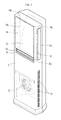
- FIG. 1 is a perspective view of an indoor unit of an air conditioner in accordance with the present invention, more particularly, a stand-type air conditioner, in which air is discharged from three surfaces.
- suction holes 12 for inhaling indoor air therethrough are formed through the lower portions of the side surfaces of an indoor unit 10, and a plurality of discharge holes 14, 16, and 18 for discharging the air, inhaled through the suction holes 12, to an indoor space therethrough are formed through the upper portion of the indoor unit 10.
- the plurality of discharge holes 14, 16, and 18 include a left discharge hole 14 formed through the upper portion of the left side surface of the indoor unit 10, a right discharge hole 16 formed through the upper portion of the right side surface of the indoor unit 10, and a front discharge hole 18 formed through the central portion of the front surface of the indoor unit 10.
- Blades 14a, 16a, and 18a for opening and closing the discharge holes 14, 16, 18 and adjusting the directions of air discharged through the discharge holes 14, 16, and 18 are respectively provided in the discharge holes 14, 16, and 18.
- First to third stepping motors 14b, 16b, and 18b for rotating the blades 14a, 16a, and 18a are respectively provided at the blades 14a, 16a, and 18a.
- the first to third stepping motors 14b, 16b, and 18b for separately rotating the blades 14a, 16a, and 18a provided in the discharge holes 14, 16, and 18 are respectively provided at the blades 14a, 16a, and 18a, and rotate the blades 14a, 16a, and 18a at designated angles according to rotating amounts thereof.
- the blades 14a, 16a, and 18a can change their directions continuously as well as by stages, thus being operated in a swing mode.
- Any power unit, which can change the directions of the blades 14a, 16a, and 18a continuously as well as by stages, may be used as the first to third stepping motors 14b, 16b, and 18b.
- the stepping motors 14b, 16b, and 18b are driven, and thus rotate connection members (not shown) connected to driving shafts of the stepping motors 14b, 16b, and 18b. Thereby, the rotational angles of the blades 14a, 16a, and 18a are changed.
- the directions of air discharged through the discharge holes 14, 16, and 18 are adjusted according to the changed rotational angles of the blades 14a, 16a, and 18a, and the discharge holes 14, 16, and 18 are opened and closed according to the rotational angles of the blades 14a, 16a, and 18a.
- the blades 14a, 16a, and 18a are rotated in the range of an angle of 0° to 70°.
- the blade 14a provided in the left discharge hole 14 is referred to as the left blade
- the blade 16a provided in the right discharge hole 16 is referred to as the right blade
- the blade 18a provided in the front discharge hole 18 is referred to as the front blade.
- An indoor heat exchanger 20 for converting indoor air inhaled through the suction holes 12 into cool air or warm air through latent heat of vaporization of a refrigerant and an indoor fan 22 for blowing the air, which has been heat-exchanged by the indoor heat exchanger 20, are installed in the indoor unit 10.
- FIG. 2 is a control diagram of an apparatus for controlling an air current in a sleep mode of an air conditioner in accordance with one embodiment of the present invention.
- the apparatus includes an input unit 100, an indoor temperature sensing unit 110, a control unit 120, a compressor driving unit 130, an indoor fan driving unit 140, a blade driving unit 150, and a display unit 160.
- the input unit 100 includes a key operating unit or a remote controller signal receiving unit so as to input an operating mode (for example, a cooling, heating or sleep mode) and operation data, such as a control temperature (Ts), a designated volume of air, and a designated direction of air.
- the indoor temperature sensing unit 110 senses the temperature (Tr) of indoor air inhaled into the indoor unit 10.
- the control unit 120 is a micro computer for controlling a cooling, heating or sleep operation according to the operating mode inputted by the input unit 100.
- the control unit 120 adjusts the angles of the blades 14a, 16a, and 18a according to the results of comparison between the indoor temperatures (Tr) and the control temperature (Ts) to control the directions of air discharged through the discharge holes 14, 16, and 18, and differently adjusts the number of rotations of the indoor fan 22 according to whether a compressor 132 is operated to control the volume of the discharged air.
- control unit 120 adjusts the angles of the blades 14a, 16a, and 18a according to the results of the comparison between the indoor temperatures (Tr) and the control temperature (Ts), thus controlling the directions of air discharged through the discharge holes 14, 16, and 18.
- Tr indoor temperatures
- Ts control temperature
- the discharged air having a direction, which directly faces a user so as to sense an air current, by adjusting the angles of the blades 14a, 16a, and 18a is defined as a direct wind
- the discharged air having a direction, which does not directly face the user so as not to sense an air current, by adjusting the angles of the blades 14a, 16a, and 18a is defined as an indirect wind
- the discharged air having a direction, which intermittently faces the user so as to intermittently sense an air current, by adjusting the angles of the blades 14a, 16a, and 18a is defined as an intermittent wind.
- the intermittent wind is obtained by the reciprocation (swing) of the blades 14a, 16a, and 18a between an angle producing the direct wind and an angle producing the indirect wind.
- the intermittent wind which is obtained by the stay of the blades 14a, 16a, and 18a at the angle producing the direct wind for a longer time than the angle producing the indirect wind, is defined as a direct intermittent wind
- the intermittent wind which is obtained by the stay of the blades 14a, 16a, and 18a at the angle producing the indirect wind for a longer time than the angle producing the direct wind, is defined as an indirect intermittent wind.
- the angles of the blades 14a, 16a, and 18a producing the direct wind, the indirect wind, the direct intermittent wind, and the indirect intermittent wind and the times to blowing the direct wind, the indirect wind, the direct intermittent wind, and the indirect intermittent wind are stored in a ROM table of the control unit 120.
- the control unit 120 controls the directions of air discharged through the discharge holes 14, 16, and 18 so as to produce the indirect wind
- the control unit 120 controls the directions of air discharged through the discharge holes 14, 16, and 18 so as to produce the indirect wind
- the control temperature (Ts) may be a temperature, which is set by a user, or a temperature pattern, which is programmed in the sleep mode.
- the compressor driving unit 130 controls the operation of the compressor 132 according to the control signal of the control unit 120
- the indoor fan driving unit 140 controls the operation of the indoor fan 22 according to the control signal of the control unit 120.
- the blade driving unit 150 includes the stepping motors 14b, 16b, and 18b for controlling the positions and the swing angles of the blades 14a, 16a, and 18a so as to adjust the directions or air discharged through the discharge holes 14, 16, and 18 according to the control signal of the control unit 120.
- the display unit 160 displays the operating state and the error mode of the air conditioner according to the display control signal of the control unit 120.
- the display unit 160 visually displays the directions of the blades 14a, 16a, and 18a, which are changed by stages, thus informing the present directions of the blades 14a, 16a, and 18a to a user.
- discharged air having a direction, which makes a user directly sense an air current is defined as a direct wind
- discharged air having a direction, which does not make the user directly sense the air current is defined as an indirect wind
- discharged air having a direction, which makes the user intermittently sense an air current is defined as an intermittent wind.
- the intermittent wind, in which the time for blowing the direct wind is longer than the time for blowing the indirect wind is defined as a direct intermittent wind
- the intermittent wind, in which the time for blowing the indirect wind is longer than the time for blowing the direct wind is defined as an indirect intermittent wind.
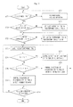
- FIG. 3 is a flow chart illustrating a method for controlling an air current in a sleep mode of an air conditioner in accordance with the present invention. Hereinafter, a cooling operation of the air conditioner will be described.
- an operating mode for example, a cooling, heating or sleep mode
- operation data for example, a sleep operation time, a control temperature, etc. in the sleep mode
- the control unit 120 determines whether a sleep mode is inputted (S200). When it is determined that the sleep mode is not inputted, the control unit 120 operates the compressor 132 through the compressor driving unit 130, and adjusts the positions of the blades 14a, 16a, and 18a and the volume of air discharged from the indoor fan 22 according to values set by the user, thus performing a normal cooling operation (S202).
- the control unit 120 determines whether the sleep operation time is inputted through the input unit 100 according to user's instructions, before the sleep mode is operated (S204). When it is determined that the sleep operation time is not inputted, the control unit 120 sets the sleep operation time to a default value (approximately 8 hours), which is predetermined in the control unit 120 (usually, a period from the time of going to bed to the time of getting up from bed) (S206).
- a default value approximately 8 hours
- the control unit 120 determines whether the control temperature (Ts) in the sleep mode is inputted through the input unit 100 according to user's instructions (S208). When it is determined that the control temperature (Ts) in the sleep mode is not inputted, the control unit 120 sets the control temperature (Ts) to a default value, which is predetermined in the control unit 120, (S210).
- the control unit 120 senses an indoor temperature (Tr) through the indoor temperature sensing unit 110 so as to control the directions of air in the sleep mode (S212).
- the control unit 120 compares the sensed indoor temperature (Tr) with the control temperature (Ts, approximately 27 ⁇ 28°C) (S214). As the results of the comparison, when it is determined that the sensed indoor temperature (Tr) is lower than the control temperature (Ts), an indoor space has temperature conditions, which lowers the skin temperature of the user to go to bed, and thus the control unit 120 controls air discharged from the discharge holes 14, 16, and 18 to have a direction for producing an indirect wind so as to minimize the operation of a nerve center controlling the temperature of a human body (S216).
- the control unit 120 determines whether the indoor temperature (Tr) is not lower than the control unit (Ts) and is not higher than the control temperature (Ts) + P (here, P is approximately 1°C) (S218).
- the indoor space has temperature conditions, which maintains the comfortable state of the skin temperature of the user to go to bed, and thus the control unit 120 controls air discharged from the discharge holes 14, 16, and 18 to have a direction for producing an indirect intermittent wind (S220).
- control unit 120 controls air discharged from the discharge holes 14, 16, and 18 to have a direction for producing an direct intermittent wind so as to prevent the skin temperature from rising (S222).
- control unit 120 controls the directions of the air discharged from the discharge holes 14, 16, and 18 to produce the indirect wind, the indirect intermittent wind, or the direct intermittent wind according to the results of the comparison between the indoor temperature (Tr) and the control temperature (Ts), thus allowing the user to intermittently sense an air current and comfortably maintaining the skin temperature of the user. Further, the control unit 120 increases the control temperature (Ts), compared with the sleep mode of the conventional air conditioner, thus reducing power consumption.
- the control unit 120 determines whether the predetermined sleep operation time has elapsed (S224). When it is determined that the sleep operation time has not elapsed, the method is fed back into the step S212. Thereby, in the sleep mode, the control unit 120 senses the indoor temperature (Tr), which is changed, and continuously controls the directions of the air discharged from the discharge holes 14, 16, and 18 to produce the indirect wind, the indirect intermittent wind, and the direct intermittent wind.
- Tr indoor temperature
- control unit 120 stops the operations of all loads, thus terminating the operation of the air conditioner in the sleep mode.
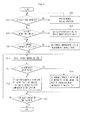
- FIG. 4 is a flow chart illustrating a method for controlling an air current in a sleep mode of an air conditioner by adjusting a number rotations of an indoor fan for saving power in accordance with another embodiment of the present invention. Some elements of FIG. 4 are substantially the same as those of FIG. 3, and a detailed description thereof will thus be omitted because it is considered to be unnecessary.
- an operating mode for example, a cooling, heating or sleep mode
- operation data for example, a sleep operation time, a control temperature, etc. in the sleep mode
- the control unit 120 determines whether a sleep mode is inputted (S300). When it is determined that the sleep mode is not inputted, the control unit 120 performs a normal cooling operation (S302).
- the control unit 120 determines whether the sleep operation time is inputted through the input unit 100 according to user's instructions, before the sleep mode is operated (S304). When it is determined that the sleep operation time is not inputted, the control unit 120 sets a sleep operation time, which is predetermined in the control unit 120, to a default value (S306).
- the control unit 120 determines whether the control temperature (Ts) in the sleep mode is inputted through the input unit 100 according to user's instructions (S308). When it is determined that the control temperature (Ts) in the sleep mode is not inputted, the control unit 120 sets a control temperature (Ts), which is predetermined in the control unit 120, to a default value (S310).
- the control unit 120 senses an indoor temperature (Tr) through the indoor temperature sensing unit 110 so as to switch on or off the compressor 132 (S312).
- the control unit 120 determines whether the compressor 132 is switched on by comparing the indoor temperature (Tr) with the control temperature (Ts) (S314).
- the control unit 120 sets the minimum number of rotations of the indoor fan 22 to be larger than that of the indoor fan 22 when the compressor is switched off (S316). That is, the minimum number of rotations of the indoor fan 22 is set to approximately 300RPM.
- the control unit 120 sets the minimum number of rotations of the indoor fan 22 to be smaller than that of the indoor fan 22 (approximately, 300RPM) when the compressor is switched on, as large as Q (approximately, 50RPM) (S318). That is, the minimum number of rotations of the indoor fan 22 is set to approximately 250RPM.
- the minimum number of rotations of the indoor fan 22 when the compressor 132 is switched off is smaller than that of the indoor fan 22 when the compressor 132 is switched on, thus reducing user sensitivity to an air current when the discharged air produces an indirect wind while reducing power consumption.
- the control unit 120 determines whether the predetermined sleep operation time has elapsed (S320). When it is determined that the sleep operation time has not elapsed, the method is fed back into the step S312. Thereby, in the sleep mode, the control unit 120 senses the indoor temperature (Tr), which has been changed, and adjusts the minimum number of rotations of the indoor fan 22 by determining whether the compressor 132 is switched on or off according to the results of the comparison between the indoor temperature (Tr) and the control temperature (Ts).
- control unit 120 stops the operations of all loads, thus terminating the operation of the air conditioner in the sleep mode.
- the present invention provides an apparatus and method for controlling an air current in a sleep mode of an air conditioner, in which the directions of air discharged through discharge holes are differently adjusted according to the results of the comparison between an indoor temperature and a control temperature in the sleep mode so as to provide a comfortable sleeping environment to a user, and the control temperature is increased so as to reduce power consumption.
- the volume of the discharged air is controlled by adjusting a number of rotations of an indoor unit according to whether a compressor is switched on, thus reducing power consumption while reducing user sensitivity to the air current.
Landscapes
- Engineering & Computer Science (AREA)
- Chemical & Material Sciences (AREA)
- Combustion & Propulsion (AREA)
- Mechanical Engineering (AREA)
- General Engineering & Computer Science (AREA)
- Signal Processing (AREA)
- Physics & Mathematics (AREA)
- Fuzzy Systems (AREA)
- Mathematical Physics (AREA)
- Human Computer Interaction (AREA)
- Air Conditioning Control Device (AREA)
Applications Claiming Priority (1)
| Application Number | Priority Date | Filing Date | Title |
|---|---|---|---|
| KR1020060116079A KR20080046522A (ko) | 2006-11-22 | 2006-11-22 | 공기조화기의 취침운전 시 기류제어장치 및 그 방법 |
Publications (3)
| Publication Number | Publication Date |
|---|---|
| EP1925887A2 true EP1925887A2 (de) | 2008-05-28 |
| EP1925887A3 EP1925887A3 (de) | 2013-03-06 |
| EP1925887B1 EP1925887B1 (de) | 2017-08-30 |
Family
ID=38805075
Family Applications (1)
| Application Number | Title | Priority Date | Filing Date |
|---|---|---|---|
| EP07108537.7A Active EP1925887B1 (de) | 2006-11-22 | 2007-05-21 | Vorrichtung und Verfahren zur Steuerung des Luftstroms einer Klimaanlage im Schlafmodus |
Country Status (4)
| Country | Link |
|---|---|
| EP (1) | EP1925887B1 (de) |
| KR (1) | KR20080046522A (de) |
| CN (1) | CN101187491B (de) |
| ES (1) | ES2649754T3 (de) |
Cited By (5)
| Publication number | Priority date | Publication date | Assignee | Title |
|---|---|---|---|---|
| CN102147138A (zh) * | 2010-02-04 | 2011-08-10 | 珠海格力电器股份有限公司 | 空调器睡眠模式的控制方法 |
| CN105147242A (zh) * | 2015-06-17 | 2015-12-16 | 四川长虹电器股份有限公司 | 一种睡眠环境监测装置及其监测方法 |
| WO2018117352A1 (en) * | 2016-12-21 | 2018-06-28 | Samsung Electronics Co., Ltd. | Air conditioner and control method thereof |
| JP2019117039A (ja) * | 2017-12-27 | 2019-07-18 | トヨタホーム株式会社 | 建物の換気システム |
| CN110895010A (zh) * | 2019-11-08 | 2020-03-20 | 珠海格力电器股份有限公司 | 一种空调的控制方法、装置、存储介质及空调 |
Families Citing this family (3)
| Publication number | Priority date | Publication date | Assignee | Title |
|---|---|---|---|---|
| CN105042806B (zh) * | 2015-09-02 | 2017-12-22 | 珠海格力电器股份有限公司 | 空调器的扫风控制方法和装置 |
| KR102346657B1 (ko) * | 2017-01-25 | 2022-01-04 | 삼성전자주식회사 | 공기 조화 시스템, 공기 조화 시스템의 실내기 및 이의 제어 방법 |
| CN108826454B (zh) * | 2018-06-19 | 2019-12-31 | 珠海格力电器股份有限公司 | 除湿机的控制方法、系统、存储介质和除湿机 |
Family Cites Families (7)
| Publication number | Priority date | Publication date | Assignee | Title |
|---|---|---|---|---|
| KR920007668B1 (en) * | 1988-01-11 | 1992-09-14 | Mitsubishi Electric Corp | Air conditioner |
| JP2000171072A (ja) * | 1998-12-07 | 2000-06-23 | Sanyo Electric Co Ltd | 空気調和機 |
| KR100377619B1 (ko) * | 1999-10-20 | 2003-03-26 | 엘지전자 주식회사 | 냉방기에서의 취침 운전 제어방법 |
| KR20020002796A (ko) * | 2000-06-30 | 2002-01-10 | 구자홍 | 공기조화기의 취침운전시 풍향제어방법 |
| JP2003329282A (ja) * | 2002-05-13 | 2003-11-19 | Kenji Aoki | 夏季の睡眠生理リズムと気温変化に対応した空調プログラムをマイコンに組み込んだ、夏の睡眠不足解消をはかるエアコン用マイコンタイマー。 |
| KR100484929B1 (ko) * | 2002-07-15 | 2005-04-22 | 삼성전자주식회사 | 공기 조화기 및 그 제어방법 |
| KR101143576B1 (ko) * | 2006-01-20 | 2012-05-09 | 삼성전자주식회사 | 공기조화기의 취침운전시 풍향제어방법 |
-
2006
- 2006-11-22 KR KR1020060116079A patent/KR20080046522A/ko not_active Ceased
-
2007
- 2007-05-21 ES ES07108537.7T patent/ES2649754T3/es active Active
- 2007-05-21 EP EP07108537.7A patent/EP1925887B1/de active Active
- 2007-06-06 CN CN2007101099279A patent/CN101187491B/zh not_active Expired - Fee Related
Cited By (9)
| Publication number | Priority date | Publication date | Assignee | Title |
|---|---|---|---|---|
| CN102147138A (zh) * | 2010-02-04 | 2011-08-10 | 珠海格力电器股份有限公司 | 空调器睡眠模式的控制方法 |
| CN102147138B (zh) * | 2010-02-04 | 2013-04-24 | 珠海格力电器股份有限公司 | 空调器睡眠模式的控制方法 |
| CN105147242A (zh) * | 2015-06-17 | 2015-12-16 | 四川长虹电器股份有限公司 | 一种睡眠环境监测装置及其监测方法 |
| WO2018117352A1 (en) * | 2016-12-21 | 2018-06-28 | Samsung Electronics Co., Ltd. | Air conditioner and control method thereof |
| US10302326B2 (en) | 2016-12-21 | 2019-05-28 | Samsung Electronics Co., Ltd. | Air conditioner with housing having discharge holes and control method thereof |
| JP2019117039A (ja) * | 2017-12-27 | 2019-07-18 | トヨタホーム株式会社 | 建物の換気システム |
| JP6990107B2 (ja) | 2017-12-27 | 2022-01-12 | トヨタホーム株式会社 | 建物の換気システム |
| CN110895010A (zh) * | 2019-11-08 | 2020-03-20 | 珠海格力电器股份有限公司 | 一种空调的控制方法、装置、存储介质及空调 |
| CN110895010B (zh) * | 2019-11-08 | 2023-11-17 | 珠海格力电器股份有限公司 | 一种空调的控制方法、装置、存储介质及空调 |
Also Published As
| Publication number | Publication date |
|---|---|
| EP1925887A3 (de) | 2013-03-06 |
| ES2649754T3 (es) | 2018-01-15 |
| KR20080046522A (ko) | 2008-05-27 |
| EP1925887B1 (de) | 2017-08-30 |
| CN101187491B (zh) | 2010-06-09 |
| CN101187491A (zh) | 2008-05-28 |
Similar Documents
| Publication | Publication Date | Title |
|---|---|---|
| EP1925887B1 (de) | Vorrichtung und Verfahren zur Steuerung des Luftstroms einer Klimaanlage im Schlafmodus | |
| CN108344126B (zh) | 空气调节系统、空气调节系统的室内单元及控制其的方法 | |
| EP1998118B1 (de) | Verfahren zur Steuerung des Schlafmodusbetriebs einer Klimaanlage | |
| CN107120806B (zh) | 一种空调送风的控制方法及装置 | |
| KR20080104934A (ko) | 공기 조화기의 취침운전 제어 방법 | |
| JPH09303840A (ja) | 空気調和装置 | |
| JPH04295532A (ja) | エアコンの室内温度調整制御方法 | |
| EP1811239B1 (de) | Steuerung der Blasrichtung einer Klimaanlage in Schlafbetriebsmodus | |
| WO2024045899A1 (zh) | 空调及其制冷控制方法 | |
| KR20010019126A (ko) | 선택된 동작모드와 기능패턴에 따른 공조기기의 동작 제어방법 | |
| JP2006317142A (ja) | 天井型エアコンのベーン制御方法 | |
| JP3549401B2 (ja) | 空気調和機の運転方法 | |
| CN113669861A (zh) | 一种空调器的控制方法、空调器 | |
| CN111256210A (zh) | 一种空调及其控制方法 | |
| JP3785866B2 (ja) | 空気調和装置 | |
| JP5996991B2 (ja) | 空気調和機 | |
| JP2005147614A (ja) | 空気調和機 | |
| CN115325670B (zh) | 空调及其制冷控制方法 | |
| CN117029220B (zh) | 基于移动式温控器的风机盘管控制方法、系统及存储介质 | |
| JPH07145982A (ja) | 空気調和機 | |
| CN114413407B (zh) | 空调器的控制方法、控制装置、空调器以及存储介质 | |
| JP2003329285A (ja) | 空気調和機の制御装置、及び空気調和機 | |
| KR20170129454A (ko) | 공기조화기 및 그 운전방법 | |
| JP2008121927A (ja) | シーリングファン | |
| JP2001153422A (ja) | 空調システムの制御装置 |
Legal Events
| Date | Code | Title | Description |
|---|---|---|---|
| PUAI | Public reference made under article 153(3) epc to a published international application that has entered the european phase |
Free format text: ORIGINAL CODE: 0009012 |
|
| AK | Designated contracting states |
Kind code of ref document: A2 Designated state(s): AT BE BG CH CY CZ DE DK EE ES FI FR GB GR HU IE IS IT LI LT LU LV MC MT NL PL PT RO SE SI SK TR |
|
| AX | Request for extension of the european patent |
Extension state: AL BA HR MK RS |
|
| RAP1 | Party data changed (applicant data changed or rights of an application transferred) |
Owner name: SAMSUNG ELECTRONICS CO., LTD. |
|
| PUAL | Search report despatched |
Free format text: ORIGINAL CODE: 0009013 |
|
| AK | Designated contracting states |
Kind code of ref document: A3 Designated state(s): AT BE BG CH CY CZ DE DK EE ES FI FR GB GR HU IE IS IT LI LT LU LV MC MT NL PL PT RO SE SI SK TR |
|
| AX | Request for extension of the european patent |
Extension state: AL BA HR MK RS |
|
| RIC1 | Information provided on ipc code assigned before grant |
Ipc: F24F 11/00 20060101AFI20130128BHEP |
|
| 17P | Request for examination filed |
Effective date: 20130906 |
|
| RBV | Designated contracting states (corrected) |
Designated state(s): AT BE BG CH CY CZ DE DK EE ES FI FR GB GR HU IE IS IT LI LT LU LV MC MT NL PL PT RO SE SI SK TR |
|
| AKX | Designation fees paid |
Designated state(s): ES GB IT |
|
| REG | Reference to a national code |
Ref country code: DE Ref legal event code: R108 |
|
| REG | Reference to a national code |
Ref country code: DE Ref legal event code: R108 Effective date: 20131113 |
|
| 17Q | First examination report despatched |
Effective date: 20140703 |
|
| GRAP | Despatch of communication of intention to grant a patent |
Free format text: ORIGINAL CODE: EPIDOSNIGR1 |
|
| INTG | Intention to grant announced |
Effective date: 20161010 |
|
| GRAJ | Information related to disapproval of communication of intention to grant by the applicant or resumption of examination proceedings by the epo deleted |
Free format text: ORIGINAL CODE: EPIDOSDIGR1 |
|
| GRAP | Despatch of communication of intention to grant a patent |
Free format text: ORIGINAL CODE: EPIDOSNIGR1 |
|
| INTC | Intention to grant announced (deleted) | ||
| INTG | Intention to grant announced |
Effective date: 20170317 |
|
| GRAS | Grant fee paid |
Free format text: ORIGINAL CODE: EPIDOSNIGR3 |
|
| GRAA | (expected) grant |
Free format text: ORIGINAL CODE: 0009210 |
|
| AK | Designated contracting states |
Kind code of ref document: B1 Designated state(s): ES GB IT |
|
| REG | Reference to a national code |
Ref country code: GB Ref legal event code: FG4D |
|
| REG | Reference to a national code |
Ref country code: ES Ref legal event code: FG2A Ref document number: 2649754 Country of ref document: ES Kind code of ref document: T3 Effective date: 20180115 |
|
| PLBE | No opposition filed within time limit |
Free format text: ORIGINAL CODE: 0009261 |
|
| STAA | Information on the status of an ep patent application or granted ep patent |
Free format text: STATUS: NO OPPOSITION FILED WITHIN TIME LIMIT |
|
| 26N | No opposition filed |
Effective date: 20180531 |
|
| PGFP | Annual fee paid to national office [announced via postgrant information from national office to epo] |
Ref country code: IT Payment date: 20210513 Year of fee payment: 15 |
|
| PGFP | Annual fee paid to national office [announced via postgrant information from national office to epo] |
Ref country code: ES Payment date: 20210610 Year of fee payment: 15 |
|
| REG | Reference to a national code |
Ref country code: ES Ref legal event code: FD2A Effective date: 20230630 |
|
| PG25 | Lapsed in a contracting state [announced via postgrant information from national office to epo] |
Ref country code: IT Free format text: LAPSE BECAUSE OF NON-PAYMENT OF DUE FEES Effective date: 20220521 Ref country code: ES Free format text: LAPSE BECAUSE OF NON-PAYMENT OF DUE FEES Effective date: 20220522 |
|
| PGFP | Annual fee paid to national office [announced via postgrant information from national office to epo] |
Ref country code: GB Payment date: 20260324 Year of fee payment: 20 |