EP1925891A2 - Photovoltaic power station - Google Patents
Photovoltaic power station Download PDFInfo
- Publication number
- EP1925891A2 EP1925891A2 EP07386027A EP07386027A EP1925891A2 EP 1925891 A2 EP1925891 A2 EP 1925891A2 EP 07386027 A EP07386027 A EP 07386027A EP 07386027 A EP07386027 A EP 07386027A EP 1925891 A2 EP1925891 A2 EP 1925891A2
- Authority
- EP
- European Patent Office
- Prior art keywords
- space lattice
- lattice structure
- arrays
- configuration
- space
- Prior art date
- Legal status (The legal status is an assumption and is not a legal conclusion. Google has not performed a legal analysis and makes no representation as to the accuracy of the status listed.)
- Granted
Links
- 238000003491 array Methods 0.000 claims abstract description 28
- 238000010276 construction Methods 0.000 description 5
- 230000007246 mechanism Effects 0.000 description 5
- 230000007423 decrease Effects 0.000 description 3
- 239000002184 metal Substances 0.000 description 3
- 239000007787 solid Substances 0.000 description 2
- 238000006243 chemical reaction Methods 0.000 description 1
- 230000003247 decreasing effect Effects 0.000 description 1
- 230000008030 elimination Effects 0.000 description 1
- 238000003379 elimination reaction Methods 0.000 description 1
- 239000002803 fossil fuel Substances 0.000 description 1
- 238000004519 manufacturing process Methods 0.000 description 1
- 230000007935 neutral effect Effects 0.000 description 1
- 230000000452 restraining effect Effects 0.000 description 1
Images


Classifications
-
- F—MECHANICAL ENGINEERING; LIGHTING; HEATING; WEAPONS; BLASTING
- F24—HEATING; RANGES; VENTILATING
- F24S—SOLAR HEAT COLLECTORS; SOLAR HEAT SYSTEMS
- F24S30/00—Arrangements for moving or orienting solar heat collector modules
- F24S30/40—Arrangements for moving or orienting solar heat collector modules for rotary movement
- F24S30/45—Arrangements for moving or orienting solar heat collector modules for rotary movement with two rotation axes
- F24S30/452—Vertical primary axis
-
- F—MECHANICAL ENGINEERING; LIGHTING; HEATING; WEAPONS; BLASTING
- F24—HEATING; RANGES; VENTILATING
- F24S—SOLAR HEAT COLLECTORS; SOLAR HEAT SYSTEMS
- F24S30/00—Arrangements for moving or orienting solar heat collector modules
- F24S30/40—Arrangements for moving or orienting solar heat collector modules for rotary movement
-
- F—MECHANICAL ENGINEERING; LIGHTING; HEATING; WEAPONS; BLASTING
- F24—HEATING; RANGES; VENTILATING
- F24S—SOLAR HEAT COLLECTORS; SOLAR HEAT SYSTEMS
- F24S25/00—Arrangement of stationary mountings or supports for solar heat collector modules
-
- H—ELECTRICITY
- H02—GENERATION; CONVERSION OR DISTRIBUTION OF ELECTRIC POWER
- H02S—GENERATION OF ELECTRIC POWER BY CONVERSION OF INFRARED RADIATION, VISIBLE LIGHT OR ULTRAVIOLET LIGHT, e.g. USING PHOTOVOLTAIC [PV] MODULES
- H02S20/00—Supporting structures for PV modules
-
- H—ELECTRICITY
- H02—GENERATION; CONVERSION OR DISTRIBUTION OF ELECTRIC POWER
- H02S—GENERATION OF ELECTRIC POWER BY CONVERSION OF INFRARED RADIATION, VISIBLE LIGHT OR ULTRAVIOLET LIGHT, e.g. USING PHOTOVOLTAIC [PV] MODULES
- H02S30/00—Structural details of PV modules other than those related to light conversion
- H02S30/10—Frame structures
-
- F—MECHANICAL ENGINEERING; LIGHTING; HEATING; WEAPONS; BLASTING
- F24—HEATING; RANGES; VENTILATING
- F24S—SOLAR HEAT COLLECTORS; SOLAR HEAT SYSTEMS
- F24S25/00—Arrangement of stationary mountings or supports for solar heat collector modules
- F24S2025/01—Special support components; Methods of use
- F24S2025/02—Ballasting means
-
- F—MECHANICAL ENGINEERING; LIGHTING; HEATING; WEAPONS; BLASTING
- F24—HEATING; RANGES; VENTILATING
- F24S—SOLAR HEAT COLLECTORS; SOLAR HEAT SYSTEMS
- F24S25/00—Arrangement of stationary mountings or supports for solar heat collector modules
- F24S25/10—Arrangement of stationary mountings or supports for solar heat collector modules extending in directions away from a supporting surface
- F24S25/13—Profile arrangements, e.g. trusses
-
- Y—GENERAL TAGGING OF NEW TECHNOLOGICAL DEVELOPMENTS; GENERAL TAGGING OF CROSS-SECTIONAL TECHNOLOGIES SPANNING OVER SEVERAL SECTIONS OF THE IPC; TECHNICAL SUBJECTS COVERED BY FORMER USPC CROSS-REFERENCE ART COLLECTIONS [XRACs] AND DIGESTS
- Y02—TECHNOLOGIES OR APPLICATIONS FOR MITIGATION OR ADAPTATION AGAINST CLIMATE CHANGE
- Y02E—REDUCTION OF GREENHOUSE GAS [GHG] EMISSIONS, RELATED TO ENERGY GENERATION, TRANSMISSION OR DISTRIBUTION
- Y02E10/00—Energy generation through renewable energy sources
- Y02E10/40—Solar thermal energy, e.g. solar towers
- Y02E10/47—Mountings or tracking
-
- Y—GENERAL TAGGING OF NEW TECHNOLOGICAL DEVELOPMENTS; GENERAL TAGGING OF CROSS-SECTIONAL TECHNOLOGIES SPANNING OVER SEVERAL SECTIONS OF THE IPC; TECHNICAL SUBJECTS COVERED BY FORMER USPC CROSS-REFERENCE ART COLLECTIONS [XRACs] AND DIGESTS
- Y02—TECHNOLOGIES OR APPLICATIONS FOR MITIGATION OR ADAPTATION AGAINST CLIMATE CHANGE
- Y02E—REDUCTION OF GREENHOUSE GAS [GHG] EMISSIONS, RELATED TO ENERGY GENERATION, TRANSMISSION OR DISTRIBUTION
- Y02E10/00—Energy generation through renewable energy sources
- Y02E10/50—Photovoltaic [PV] energy
Definitions
- This invention relates to a photovoltaic power station, which produces electrical energy from solar energy, which comprises: at least two arrays of photovoltaic cells and at least two flat structures, at least one space lattice structure which is configured with framework members and node connectors which are interconnected in a configuration which consists of polyhedra, at least one foundation which bears a bearing plane; in which: the at least two arrays of photovoltaic cells are fixed on the at least two flat structures respectively, the at least two flat structures are connected to the at least one space lattice structure, the at least one space lattice structure rotates, with respect to the foundation, about one and only one axis which is perpendicular to the bearing plane.
- the arrays of photovoltaic cells are fixed on flat structures, e.g. beam grids, or on flat space lattice configurations, which are mounted on rotation systems, each of which rotates about just one axis which is perpendicular to its horizontal bearing plane on a support or base, or rotates about two axes, one axis which is perpendicular to its horizontal bearing plane and one which is parallel to the same plane.
- the rotational movements of these rotation systems are realized with rotation mechanisms or rotation mechanisms with hydraulic cylinders, and their positioning with respect to the sun is achieved through one or two encoders and with the use of the above-mentioned software.
- Photovoltaic power stations of this type are well known. They have, however, the following disadvantages:
- the aims of the present invention were both the elimination of these drawbacks and the realization of a photovoltaic power station which comprises arrays of photovoltaic cells, which perform translational and rotational movements, fixed, in subsets or groups, on space structures whose sizes are such that the total surface area of photovoltaic cells per group is at least one order of magnitude (ten times) greater than the surface area of photovoltaic cells, which the largest known rotation systems of this type move.
- a photovoltaic power station which comprises a set of space frame structures, each of which has a foundation which bears a bearing plane, characterized in that:
- the interconnection of framework members is carried out in any suitable manner which is susceptible of industrial application and always according to generally accepted technical rules e.g. the structural Eurocodes.
- the above-mentioned space frame structures are space lattice structures.
- Their framework members are thin walled metal circular hollow sections and their construction is carried out according to, e.g., patent No. GR1004187 .
- Figure 4 shows an octahedron and tetrahedron assembled together, which are configured with a number of framework members pin-connected at their ends in any suitable manner, as by node connectors 1 which are susceptible of industrial application, so that the interconnection of framework members is carried out at minimum cost.
- the framework members are the edges and the node connectors 1 are the vertexes of the polyhedrons.
- the faces of the polyhedrons which are configured in this manner are left to be imagined.
- the octahedron and the tetrahedron are separated for clear illustration of the forms of these two kinds of polyhedrons.
- the octahedron has twelve framework members and eight, equal equilateral, triangular faces.
- three of the framework members havebeen shown by dot-dash lines because, when the octahedron O and the tetrahedron T are assembled as in figure 4 , these framework members are common to O and T .
- a space frame structure according to the present invention in which the framework members are pin-connected to the node connectors 1, is characterized in that it has integrity of its configuration; and the structure is characterized by complete vector equilibrium, independent of the boundary and loading conditions. We thus have a space frame structure which behaves like a solid body.
- the second manner is to configure a configuration which consists of polyhedra, the configurations of which have integrity and which are characterized by complete vector equilibrium, e.g. octahedrons and tetrahedrons.
- the third manner is to configure a configuration which consists of polyhedra, the configurations of which have integrity, just as the octahedron O and the tetrahedron T , and polyhedra the configurations of which do not have integrity, just as the cubeoctahedron CO , the semi-octahedron 1 ⁇ 2 O , the semi-cubeoctahedron 1 ⁇ 2 CO ; so that, if we consider the integrity of the configuration which is configured in this manner, the space lattice structure will be characterized by complete vector equilibrium.
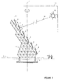
- Figure 1 shows a set of arrays of photovoltaic cells 2 which are fixed on flat structures 3, a space frame structure 4 to which the flat structures 3 are connected, and a foundation 6 which bears a bearing plane 5.
- the set of arrays of photovoltaic cells 2 is a subset of the superset of arrays of photovoltaic cells of the photovoltaic power station according to the present invention.
- the space frame structure of figure 1 rotates, with respect to the above-mentioned foundation 6, about one and only one axis 7, which is perpendicular to the bearing plane 5.
- the rotational movement about axis 7 is carried out in such a way that the space frame structure 4 follows only the East - West daily movement of the sun 10, so that the rays 12 of the sun 10 are perpendicular to the parallel axes 8.
- the rotational movements of the flat structures 3 about the axes 8 are carried out in such a way that the planes of the arrays of photovoltaic cells 2 are perpendicular to the rays 12 of the sun 10 and, in this way, follow the elevational angle of the sun 10.
- the rotational movement of the space frame structure 4 about the axis 7 is realized with a specific rotation mechanism and the positioning is achieved through an encoder, using a software for the determination of the East-West position (the azimuthal angle) of the sun, as a function of the geographical latitude and longitude of the photovoltaic power station, the date and the time.
- the rotational movements of the flat structures 3 about axes 8 are realized with rotation mechanisms and the positioning of the elevational angle of the sun is achieved through a second encoder, using a software for the determination of the elevational angle of the sun, as a function of the geographical latitude and longitude of the photovoltaic power station, the date and the time.
- the sectional view of the space frame structure of figure 1 which is shown in figure 2 , is done by the plane which passes through axis 7 and is perpendicular to the parallel axes 8; and which in figure 2 coincides with plane 11 which is determined by the axis 7 and the center of the sun 10.
- the imaginary ray 12 of the sun 10 which is shown in figure 2 is perpendicular to the plane of any one of the arrays of photovoltaic cells 2.
- the space frame structure which is shown in figure 2 comprises a space lattice structure which is configured with octahedrons O , tetrahedrons T and semi-octahedrons 1 ⁇ 2 O , as has been illustrated hereinbefore and with reference to figures 4, 5 and 3 , the framework members are thin walled metal tubes and the structure is realized, e.g. according to patent No. GR1004187 , with identical framework members (of the same length, section and ends) and with identical node connectors 1 (of the same size; and of the same orientation and size, of holes).
- the space lattice structure of figures 1 and 2 were configured only with octahedrons O and tetrahedrons T , then it could be expanded in space just in four directions (perpendicular to the four faces of any tetrahedron T ) and could form just four corresponding sets of parallel plane surfaces, perpendicular to these directions, for fixing arrays of photovoltaic cells 2.
- the semi-octahedron 1 ⁇ 2 O we have one more direction and one more plane surface, that to which the flat structures 3, which bear the arrays of photovoltaic cells, are connected.
Landscapes
- Engineering & Computer Science (AREA)
- Physics & Mathematics (AREA)
- Life Sciences & Earth Sciences (AREA)
- Sustainable Development (AREA)
- Sustainable Energy (AREA)
- Thermal Sciences (AREA)
- Chemical & Material Sciences (AREA)
- Combustion & Propulsion (AREA)
- Mechanical Engineering (AREA)
- General Engineering & Computer Science (AREA)
- Photovoltaic Devices (AREA)
Abstract
Description
- This invention relates to a photovoltaic power station, which produces electrical energy from solar energy, which comprises: at least two arrays of photovoltaic cells and at least two flat structures, at least one space lattice structure which is configured with framework members and node connectors which are interconnected in a configuration which consists of polyhedra, at least one foundation which bears a bearing plane; in which: the at least two arrays of photovoltaic cells are fixed on the at least two flat structures respectively, the at least two flat structures are connected to the at least one space lattice structure, the at least one space lattice structure rotates, with respect to the foundation, about one and only one axis which is perpendicular to the bearing plane.
- It is well known that the efficiency of photovoltaic power stations, which produce electrical energy from solar energy with the use of arrays of photovoltaic cells, is increased by 15% - 45% when these arrays are fixed on structures, each of which performs a rotational movement about a vertical axis, or rotational movements about a vertical and about a horizontal axis, so that the surfaces of the above-mentioned arrays of photovoltaic cells are continuously approximately perpendicular to the rays of the sun during its daily movement with respect to the earth.
- It is also well known that in the above photovoltaic power stations the determination of the azimuthal and elevational angle of the sun is carried out with the use of a software, which is based on an algorithm for the determination of the position of the sun as a function of the geographical latitude and longitude of the position of the photovoltaic power station, the date and the time.
- In photovoltaic power stations of this type the arrays of photovoltaic cells are fixed on flat structures, e.g. beam grids, or on flat space lattice configurations, which are mounted on rotation systems, each of which rotates about just one axis which is perpendicular to its horizontal bearing plane on a support or base, or rotates about two axes, one axis which is perpendicular to its horizontal bearing plane and one which is parallel to the same plane. The rotational movements of these rotation systems are realized with rotation mechanisms or rotation mechanisms with hydraulic cylinders, and their positioning with respect to the sun is achieved through one or two encoders and with the use of the above-mentioned software.
- Photovoltaic power stations of this type are well known. They have, however, the following disadvantages:
- Each of the above-mentioned rotation systems rotates just one array of photovoltaic cells, which has a surface area of much less than 50 m2.
- When each of the above-mentioned rotation systems rotates about just one axis (the vertical axis) and in this way the corresponding array of photovoltaic cells follows only the azimuthal angle of the sun (only the daily East-West movement and not the elevational angle), the efficiency of these arrays of photovoltaic cells is greater than the efficiency of the fixed, with respect to the earth, arrays. These rotation systems have a lower cost; they cannot, however, be constructed economically on a large scale.
- When each of the above-mentioned rotation systems rotates about two axes and in this way the corresponding array of photovoltaic cells follows both the azimuthal and elevational angle of the sun, the efficiency of these arrays of photovoltaic cells is maximum, but the rotation systems of this type cannot be constructed economically on a large scale. Each of the larger known rotation systems of this type rotates just one array of photovoltaic cells of total surface area of the order of 50 m2 and since they are not strong enough against high wind velocities, high snow load and local concentrations of snow or ice, they have self-protection systems, e.g. at wind velocities above a limiting value they get a horizontal position in order to decrease the wind action, resulting in an expensive construction, without their reliability being increased at the same time.
- In particular, in photovoltaic power stations of this type which have flat space lattice configurations, e.g. like the one which is shown in
figure 6 , these space lattice configurations do not have integrity of their configuration, but acquire integrity (they become structures) only if they are supported (fixed) along their perimeter and in this way certain degrees of freedom are restrained. If these space lattice configurations are fixed, yet "free" in space, to rotation systems from central nodes, these rotation systems have to be strong enough and capable of restraining certain degrees of freedom of these configurations, so that these configurations acquire integrity and become structures. - The aims of the present invention were both the elimination of these drawbacks and the realization of a photovoltaic power station which comprises arrays of photovoltaic cells, which perform translational and rotational movements, fixed, in subsets or groups, on space structures whose sizes are such that the total surface area of photovoltaic cells per group is at least one order of magnitude (ten times) greater than the surface area of photovoltaic cells, which the largest known rotation systems of this type move.
- This has been achieved by a photovoltaic power station which comprises a set of space frame structures, each of which has a foundation which bears a bearing plane, characterized in that:
- each of the above-mentioned space frame structures has integrity of its configuration,
- each of the above-mentioned space frame structures has a set of flat structures which are connected to it and each flat structure bears an array of photovoltaic cells,
- each of the above-mentioned space frame structures rotates, with respect to the above-mentioned foundation, about just one axis which is perpendicular to the above-mentioned bearing plane,
- each of the above-mentioned space frame structures comprises at least one space lattice structure,
- the above-mentioned flat structures are firmly or rotationally connected to each of the above-mentioned space frame structures.
- In order to configure space frame structures according to the present invention, the interconnection of framework members is carried out in any suitable manner which is susceptible of industrial application and always according to generally accepted technical rules e.g. the structural Eurocodes.
- In particular, in order to configure, according to the present invention, space frame structures or space lattice structures with framework members which have metal tubular ends, the interconnection of these framework members is carried out with standard node connectors or connection systems, so that the industrial manufacturing of both framework members and node connectors is carried out at minimum cost and according to generally accepted technical rules. Two manners of this type of interconnection are known from patent Nos.
GR1004166 GR1004187 - According to the best mode contemplated for carrying out the present invention, the above-mentioned space frame structures are space lattice structures. Their framework members are thin walled metal circular hollow sections and their construction is carried out according to, e.g., patent No.
GR1004187 - Some advantages of the present invention are that:
- It provides a high efficiency solution for the exploitation of solar energy, decreases the dependency on fossil fuels and, in consequence, it assists in the decrease of CO2 emissions of a country.
- The realization of large scale photovoltaic power stations, which have electric power e.g. at least ten times greater than the electric power of the known photovoltaic power stations of this type, is made possible.
- Due to the greater distance of the arrays of photovoltaic cells from the surface of the earth, these arrays are better cooled by the wind and, in consequence, their efficiency is increased, particularly during the summer months.
- Due to the greater distance of the arrays of photovoltaic cells from the surface of the earth, these arrays have cleaner surfaces and, in consequence, higher efficiency.
- Because of the relatively high cost of photovoltaic cells, an increase in their annual output e.g. by 30%, as a result of the present invention, means an exceptionally high annual rate of return of investment which corresponds to the cost of the construction of the space frame or space lattice structures according to the present invention. With reference to the return period of the total investment, this period is decreased by approximately 20%.
- Due to the elevational arrangement of the arrays of photovoltaic cells, the construction of photovoltaic power stations according to the present invention becomes more economically viable in regions with high land cost.
-
- Octahedron O.- Polyhedron which has eight, equal equilateral, triangular faces which are configured with interconnected framework members which can carry predominantly axial forces.
- Tetrahedron T.- Polyhedron which has four, equal equilateral, triangular faces which are configured with interconnected framework members which can carry predominantly axial forces.
- Cubeoctahedron CO.- Polyhedron which has eight, equal equilateral, triangular and six, equal, square faces which are configured with interconnected framework members which can carry predominantly axial forces, so that there are two triangular and two square faces at each vertex.
- Semi-octahedron ½O.- Either one of the two equal polyhedra formed by the cross-section, perpendicular to an axis which passes through two opposite vertexes, of an octahedron. Semi-cubeoctahedron ½CO.- Either one of the two equal polyhedra formed by the cross-section, perpendicular to the axis which passes through the centers of two opposite square faces, of a cubeoctahedron and the addition of four equal framework members for the configuration of the square face of the cross-section.
- Space frame structure.- A three-dimensional, as a whole, structure, which is configured with interconnected framework members which can carry predominantly axial forces, the configuration of which has integrity and which is characterized by complete vector equilibrium.
- Space lattice structure.- A space frame structure which is configured with polyhedrons, which are selected from the set whose members are octahedron, tetrahedron, cubeoctahedron, semi-octahedron, semi-cubeoctahedron, and assembled in a face to face relationship. For example, a space lattice structure of type O + T is an assemblage of octahedrons and tetrahedrons in a face to face relationship.
- The invention is described below with the aid of an example and with reference to the accompanying figures, in which:
-
Figure 1 shows a set of arrays of photovoltaic cells and a space frame structure of a photovoltaic power station, according to the present invention. -
Figure 2 shows a sectional view of the space frame structure offigure 1 . -
Figure 3 shows a space lattice configuration of type O + T , which is part of the space frame structure offigure 1 . -
Figure 4 shows an octahedron and a tetrahedron offigure 3 assembled together. -
Figure 5 shows the octahedron and the tetrahedron offigure 4 separated for clear illustration. -
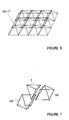
Figure 6 shows a space lattice configuration of type ½ O + T , which is part of the space frame structure offigure 1 . -
Figure 7 shows a tetrahedron and two semi-octahedrons offigure 6 separated for clear illustration. -
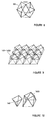
Figure 8 shows a cubeoctahedron according to its definition in the description of the present invention. -
Figure 9 shows a space lattice configuration of type ½ O + ½ CO. -
Figure 10 shows a semi-octahedron and a semi-cubeoctahedron offigure 9 separated for clear illustration. - In order to illustrate the definitions of terms in the description of the present invention, reference is made first to
figures 4 and 5 . -
Figure 4 shows an octahedron and tetrahedron assembled together, which are configured with a number of framework members pin-connected at their ends in any suitable manner, as bynode connectors 1 which are susceptible of industrial application, so that the interconnection of framework members is carried out at minimum cost. The framework members are the edges and thenode connectors 1 are the vertexes of the polyhedrons. The faces of the polyhedrons which are configured in this manner are left to be imagined. - In
figure 5 the octahedron and the tetrahedron are separated for clear illustration of the forms of these two kinds of polyhedrons. The octahedron has twelve framework members and eight, equal equilateral, triangular faces. Infigure 5 , three of the framework members havebeen shown by dot-dash lines because, when the octahedron O and the tetrahedron T are assembled as infigure 4 , these framework members are common to O and T . - The space lattice configurations of type ½ O + T and ½ O + ½ CO of
figures 6 and9 are configured, with the polyhedrons offigures 7 and10 respectively, in the same manner. - If we consider the integrity of the space lattice configuration which is shown in
figure 4 , this configuration has integrity and its structure is characterized by complete vector equilibrium. In general, every configuration which consists of octahedrons O and tetrahedrons T and is assembled as is shown infigure 3 has integrity; and its structure is characterized by complete vector equilibrium (infigure 3 some framework members are not shown for clear illustration). In addition, the main axes of all the octahedrons O are parallel; and the faces of the octahedrons O and tetrahedrons T have common planes, which form the plane surfaces of the space lattice configuration, in this way. The space lattice configurations offigures 4 and 3 are space lattice structures according to the present invention. - Since the concept of integrity is not obvious, it is emphasized that this concept is closely related to the concept of configuration. In other words, if we consider the space lattice structure with respect to the relative position of its parts, the integrity is related to the assemblage of relative positions.
- When we say that a space frame structure has integrity, this means that the configuration of the space frame is constant, that is to say the assemblage of the relative positions of the node connectors and the framework members is constant. In other words, the geometry of the structure is constant. This means that: neither the configuration of the space frame structure, nor any part of it, is a mechanism; nor is the configuration of the space frame structure, nor any part of it, in a state of neutral equilibrium.
- A space frame structure according to the present invention, in which the framework members are pin-connected to the
node connectors 1, is characterized in that it has integrity of its configuration; and the structure is characterized by complete vector equilibrium, independent of the boundary and loading conditions. We thus have a space frame structure which behaves like a solid body. - The complete vector equilibrium of the configuration of a space frame structure, in which the framework members are pin-connected to the
node connectors 1, is a necessary and sufficient condition for the integrity of its configuration. - A necessary condition for the integrity of the configuration of a space frame structure, in which the framework members are pin-connected at their ends, is: E = 3·V - 6, where the numbers of framework members and
node connectors 1 are denoted by E and V, and 6 is the minimum number of support reactions, if we consider that the space frame structure behaves like a solid body (known as Maxwell's equation). - The above necessary condition is particularly useful because, if this is not satisfied, it proves that we do not have integrity of the configuration of a space frame or space lattice structure; and, as a consequence, that the space frame or space lattice structure is not characterized by complete vector equilibrium.
- Three manners for the realization of space frame or space lattice structures, the configurations of which have integrity and which are characterized by complete vector equilibrium, are described below.
- The first manner is to start with a triangle, which is configured with three framework members pin-connected to three
node connectors 1, the configuration of which has integrity and the above-mentioned necessary condition is satisfied (V = 3, E = 3 and 3·V- 6 = 3×3 - 6 = 3), and then add three more framework members, in different planes, for the location of eachfresh node connector 1. - The second manner is to configure a configuration which consists of polyhedra, the configurations of which have integrity and which are characterized by complete vector equilibrium, e.g. octahedrons and tetrahedrons.
- The third manner is to configure a configuration which consists of polyhedra, the configurations of which have integrity, just as the octahedron O and the tetrahedron T , and polyhedra the configurations of which do not have integrity, just as the cubeoctahedron CO , the semi-octahedron ½O , the semi-cubeoctahedron ½CO; so that, if we consider the integrity of the configuration which is configured in this manner, the space lattice structure will be characterized by complete vector equilibrium.
- In spite of the fact that, according to the first manner and with a minimum number of different framework members and
node connectors 1, it is possible to configure space frame structures, the configurations of which have structural integrity and which are characterized by complete vector equilibrium; according to the third manner we have more serviceable photovoltaic power stations and this with the maximum degree of industrialization of their construction. - With these fundamental concepts in mind, it is now possible to comprehend the description of a particular embodiment of the present invention according to the best mode contemplated for carrying it out.
-
Figure 1 shows a set of arrays ofphotovoltaic cells 2 which are fixed onflat structures 3, aspace frame structure 4 to which theflat structures 3 are connected, and afoundation 6 which bears abearing plane 5. The set of arrays ofphotovoltaic cells 2 is a subset of the superset of arrays of photovoltaic cells of the photovoltaic power station according to the present invention. - The space frame structure of
figure 1 rotates, with respect to the above-mentionedfoundation 6, about one and only oneaxis 7, which is perpendicular to thebearing plane 5. - The
flat structures 3, on which the arrays ofphotovoltaic cells 2 are fixed, rotate, with respect to thespace frame structure 4, aboutaxes 8 which are parallel and parallel to thebearing plane 5. - The rotational movement about
axis 7 is carried out in such a way that thespace frame structure 4 follows only the East - West daily movement of thesun 10, so that therays 12 of thesun 10 are perpendicular to theparallel axes 8. The rotational movements of theflat structures 3 about theaxes 8 are carried out in such a way that the planes of the arrays ofphotovoltaic cells 2 are perpendicular to therays 12 of thesun 10 and, in this way, follow the elevational angle of thesun 10. - The rotational movement of the
space frame structure 4 about theaxis 7 is realized with a specific rotation mechanism and the positioning is achieved through an encoder, using a software for the determination of the East-West position (the azimuthal angle) of the sun, as a function of the geographical latitude and longitude of the photovoltaic power station, the date and the time. - The rotational movements of the
flat structures 3 aboutaxes 8 are realized with rotation mechanisms and the positioning of the elevational angle of the sun is achieved through a second encoder, using a software for the determination of the elevational angle of the sun, as a function of the geographical latitude and longitude of the photovoltaic power station, the date and the time. - The sectional view of the space frame structure of
figure 1 , which is shown infigure 2 , is done by the plane which passes throughaxis 7 and is perpendicular to theparallel axes 8; and which infigure 2 coincides withplane 11 which is determined by theaxis 7 and the center of thesun 10. Theimaginary ray 12 of thesun 10 which is shown infigure 2 is perpendicular to the plane of any one of the arrays ofphotovoltaic cells 2. - The space frame structure which is shown in
figure 2 comprises a space lattice structure which is configured with octahedrons O , tetrahedrons T and semi-octahedrons ½ O , as has been illustrated hereinbefore and with reference tofigures 4, 5 and 3 , the framework members are thin walled metal tubes and the structure is realized, e.g. according to patent No.GR1004187 - If the space lattice structure of
figures 1 and2 were configured only with octahedrons O and tetrahedrons T , then it could be expanded in space just in four directions (perpendicular to the four faces of any tetrahedron T ) and could form just four corresponding sets of parallel plane surfaces, perpendicular to these directions, for fixing arrays ofphotovoltaic cells 2. With the addition of the semi-octahedron ½ O , we have one more direction and one more plane surface, that to which theflat structures 3, which bear the arrays of photovoltaic cells, are connected.
Claims (3)
- A photovoltaic power station, which produces electrical energy from solar energy, comprising:- at least two arrays of photovoltaic cells (2) and at least two flat structures (3),- at least one space lattice structure (4) which is configured with framework members and node connectors (1) which are interconnected in a configuration which consists of polyhedra,- at least one foundation (6) which bears a bearing plane (5);in which:- said at least two arrays of photovoltaic cells (2) are fixed on said at least two flat structures (3) respectively,- said at least two flat structures (3) are connected to said at least one space lattice structure (4),- said at least one space lattice structure (4) rotates, with respect to said foundation (6), about one and only one axis (7) which is perpendicular to said bearing plane (5);characterized in that:- said framework members are pin-connected to said node connectors (1); and- said polyhedra are selected from the set whose members are octahedron ( O ), tetrahedron ( T ), cubeoctahedron ( CO ), semi-octahedron (½ O ), semi-cubeoctahedron (½ CO ); and- said configuration has integrity; and- said space lattice structure (4) is characterized by complete vector equilibrium; and the necessary condition E = 3·V -6, where the numbers of framework members and node connectors (1) are denoted by E and V respectively, is satisfied.
- A photovoltaic power station according to claim 1, characterized in that:- said at least two flat structures (3) are firmly connected to said at least one space lattice structure (4).
- A photovoltaic power station according to claim 1, characterized in that:- said at least two flat structures (3) are rotationally connected to said at least one space lattice structure (4) and rotate, with respect to said at least one space lattice structure (4), about axes (8) respectively; and- said axes (8) are parallel and parallel to said bearing plane (5).
Applications Claiming Priority (1)
| Application Number | Priority Date | Filing Date | Title |
|---|---|---|---|
| GR20060100634A GR20060100634A (en) | 2006-11-21 | 2006-11-21 | Photovoltaic power-generating station. |
Publications (4)
| Publication Number | Publication Date |
|---|---|
| EP1925891A2 true EP1925891A2 (en) | 2008-05-28 |
| EP1925891A3 EP1925891A3 (en) | 2010-10-06 |
| EP1925891B1 EP1925891B1 (en) | 2014-07-02 |
| EP1925891B9 EP1925891B9 (en) | 2014-11-19 |
Family
ID=39123587
Family Applications (1)
| Application Number | Title | Priority Date | Filing Date |
|---|---|---|---|
| EP07386027.2A Not-in-force EP1925891B9 (en) | 2006-11-21 | 2007-11-20 | Photovoltaic power station |
Country Status (2)
| Country | Link |
|---|---|
| EP (1) | EP1925891B9 (en) |
| GR (1) | GR20060100634A (en) |
Cited By (9)
| Publication number | Priority date | Publication date | Assignee | Title |
|---|---|---|---|---|
| DE102008013477A1 (en) * | 2008-03-10 | 2009-09-24 | Alfons Stettmeier | Solar module carrier (tracker) |
| WO2009122450A1 (en) * | 2008-03-31 | 2009-10-08 | Pirelli & C.S.P.A. | Sun tracker device |
| EP2109151A1 (en) * | 2008-04-07 | 2009-10-14 | Costantino Ferdinado Ponziano C.E.M. S.r.l. | Sun-tracking photovoltaic apparatus |
| ITMO20080232A1 (en) * | 2008-09-12 | 2010-03-12 | Massimo Venturelli | FITTING EQUIPMENT FOR SOLAR IRRADIATION FOR CAPTURE PANELS OF IT |
| DE102009045033A1 (en) * | 2009-03-12 | 2010-10-07 | Georg-Simon-Ohm Hochschule für angewandte Wissenschaften Fachhochschule Nürnberg | Tracking unit for a solar collector |
| CN101673313B (en) * | 2009-10-15 | 2011-03-02 | 山东电力研究院 | Photovoltaic power station mathematical modeling method for transient/dynamic analysis of power system |
| ITBA20120032A1 (en) * | 2012-05-24 | 2013-11-25 | Giuseppe Giacomino | VERTICAL STRUCTURE FOR SOLAR PANELS |
| CN103938643A (en) * | 2014-04-28 | 2014-07-23 | 润峰电力有限公司 | Photovoltaic power station base construction process achieved through sand falling under action of water |
| GR1009663B (en) * | 2018-10-04 | 2019-12-05 | Γεωργιος Αχιλλεα Γκαμανης | An improved solar power station |
Family Cites Families (7)
| Publication number | Priority date | Publication date | Assignee | Title |
|---|---|---|---|---|
| US2986241A (en) * | 1956-02-07 | 1961-05-30 | Fuller Richard Buckminster | Synergetic building construction |
| US3974600A (en) * | 1971-08-30 | 1976-08-17 | Synestructics, Inc. | Minimum inventory maximum diversity building system |
| DE7726729U1 (en) * | 1977-08-29 | 1981-03-12 | M.A.N. Maschinenfabrik Augsburg-Nuernberg Ag, 8000 Muenchen | SUPPORT STRUCTURE FOR LARGE-SCALE SOLAR COLLECTORS |
| DE3500694A1 (en) * | 1985-01-11 | 1986-07-17 | Joachim Dipl.-Ing. 7000 Stuttgart Wenzel | Solar power station |
| US5448868A (en) * | 1992-10-21 | 1995-09-12 | Lalvani; Haresh | Periodic space structures composed of two nodal polyhedra for design applications |
| US5934271A (en) * | 1994-07-19 | 1999-08-10 | Anutech Pty Limited | Large aperture solar collectors with improved stability |
| DE20217671U1 (en) * | 2002-11-15 | 2003-04-10 | Schulz, Karlheinz, 64832 Babenhausen | Steel tube support structure for photovoltaic modules over motorways and traffic routes, has T-shaped masts anchored across the motorway with tubular elements mounted on transverse part of the mast for securing solar modules |
-
2006
- 2006-11-21 GR GR20060100634A patent/GR20060100634A/en not_active IP Right Cessation
-
2007
- 2007-11-20 EP EP07386027.2A patent/EP1925891B9/en not_active Not-in-force
Non-Patent Citations (1)
| Title |
|---|
| None |
Cited By (10)
| Publication number | Priority date | Publication date | Assignee | Title |
|---|---|---|---|---|
| DE102008013477A1 (en) * | 2008-03-10 | 2009-09-24 | Alfons Stettmeier | Solar module carrier (tracker) |
| WO2009122450A1 (en) * | 2008-03-31 | 2009-10-08 | Pirelli & C.S.P.A. | Sun tracker device |
| EP2109151A1 (en) * | 2008-04-07 | 2009-10-14 | Costantino Ferdinado Ponziano C.E.M. S.r.l. | Sun-tracking photovoltaic apparatus |
| ITMO20080232A1 (en) * | 2008-09-12 | 2010-03-12 | Massimo Venturelli | FITTING EQUIPMENT FOR SOLAR IRRADIATION FOR CAPTURE PANELS OF IT |
| EP2163834A1 (en) * | 2008-09-12 | 2010-03-17 | Massimo Venturelli | Device for tracking solar radiation for panels used for absorbing the said solar radiation |
| DE102009045033A1 (en) * | 2009-03-12 | 2010-10-07 | Georg-Simon-Ohm Hochschule für angewandte Wissenschaften Fachhochschule Nürnberg | Tracking unit for a solar collector |
| CN101673313B (en) * | 2009-10-15 | 2011-03-02 | 山东电力研究院 | Photovoltaic power station mathematical modeling method for transient/dynamic analysis of power system |
| ITBA20120032A1 (en) * | 2012-05-24 | 2013-11-25 | Giuseppe Giacomino | VERTICAL STRUCTURE FOR SOLAR PANELS |
| CN103938643A (en) * | 2014-04-28 | 2014-07-23 | 润峰电力有限公司 | Photovoltaic power station base construction process achieved through sand falling under action of water |
| GR1009663B (en) * | 2018-10-04 | 2019-12-05 | Γεωργιος Αχιλλεα Γκαμανης | An improved solar power station |
Also Published As
| Publication number | Publication date |
|---|---|
| GR20060100634A (en) | 2008-06-18 |
| EP1925891A3 (en) | 2010-10-06 |
| EP1925891B9 (en) | 2014-11-19 |
| EP1925891B1 (en) | 2014-07-02 |
Similar Documents
| Publication | Publication Date | Title |
|---|---|---|
| EP1925891A2 (en) | Photovoltaic power station | |
| US8188413B2 (en) | Terrestrial concentrator solar tracking photovoltaic array | |
| ES2624705T3 (en) | Pelagic sustainable energy system | |
| US8956103B2 (en) | Hydroelectricity generating unit capturing marine wave energy and marine current energy | |
| ES2289083T3 (en) | MARINE FLOATING WIND ENERGY GENERATION PLANT. | |
| AU2011291047B2 (en) | Central receiver solar system comprising a heliostat field | |
| US8967946B2 (en) | Modular wind-solar energy converting assembly | |
| GB2383978A (en) | Platform provided with a plurality of renewable energy converter systems | |
| Gurfude et al. | Energy yield of tracking type floating solar PV plant | |
| WO2012046134A1 (en) | Tracker apparatus for capturing solar energy and relative axis movement mechanism | |
| JP2012204471A (en) | Photovoltaic generation device | |
| KR20180130058A (en) | A Floating Solar Power Generating Apparatus | |
| CA2844118A1 (en) | Solar panel assembly | |
| WO2017187259A1 (en) | Sun position tracker for concentrated photo voltaic power generation system and the method for tracking thereof | |
| EP4020795A1 (en) | A floating solar array | |
| CA2849924A1 (en) | Solar panel assembly with a mounting structure | |
| WO2007096439A1 (en) | Dynamic solar tracking system | |
| US20110180125A1 (en) | Solar panels for receiving scattered light | |
| US8899763B2 (en) | Device for concentrating solar radiation with longitudinal mirrors and a longitudinal receiver | |
| KR101770957B1 (en) | Solar cell generating system | |
| Rachedi et al. | Optimal Choice in Number and Position of Reflectors on a V-Trough Solar Concentrator | |
| JP2013206886A (en) | Solar power plant | |
| Suto et al. | Power-generation characteristics of an FPM by simulation with shadow-effect analysis | |
| Hubach | Solar Tracking Using a Parallel Manipulator Mechanism to Achieve Two-Axis Position Tracking | |
| KR101980746B1 (en) | Floating type solar energy generation apparatus |
Legal Events
| Date | Code | Title | Description |
|---|---|---|---|
| PUAI | Public reference made under article 153(3) epc to a published international application that has entered the european phase |
Free format text: ORIGINAL CODE: 0009012 |
|
| AK | Designated contracting states |
Kind code of ref document: A2 Designated state(s): AT BE BG CH CY CZ DE DK EE ES FI FR GB GR HU IE IS IT LI LT LU LV MC MT NL PL PT RO SE SI SK TR |
|
| AX | Request for extension of the european patent |
Extension state: AL BA HR MK RS |
|
| REG | Reference to a national code |
Ref country code: GR Ref legal event code: PP Ref document number: 20080300014 Country of ref document: GR |
|
| PUAL | Search report despatched |
Free format text: ORIGINAL CODE: 0009013 |
|
| AK | Designated contracting states |
Kind code of ref document: A3 Designated state(s): AT BE BG CH CY CZ DE DK EE ES FI FR GB GR HU IE IS IT LI LT LU LV MC MT NL PL PT RO SE SI SK TR |
|
| AX | Request for extension of the european patent |
Extension state: AL BA HR MK RS |
|
| 17P | Request for examination filed |
Effective date: 20110308 |
|
| AKX | Designation fees paid |
Designated state(s): AT BE BG CH CY CZ DE DK EE ES FI FR GB GR HU IE IS IT LI LT LU LV MC MT NL PL PT RO SE SI SK TR |
|
| GRAP | Despatch of communication of intention to grant a patent |
Free format text: ORIGINAL CODE: EPIDOSNIGR1 |
|
| INTG | Intention to grant announced |
Effective date: 20131018 |
|
| GRAP | Despatch of communication of intention to grant a patent |
Free format text: ORIGINAL CODE: EPIDOSNIGR1 |
|
| INTG | Intention to grant announced |
Effective date: 20140313 |
|
| GRAS | Grant fee paid |
Free format text: ORIGINAL CODE: EPIDOSNIGR3 |
|
| GRAA | (expected) grant |
Free format text: ORIGINAL CODE: 0009210 |
|
| AK | Designated contracting states |
Kind code of ref document: B1 Designated state(s): AT BE BG CH CY CZ DE DK EE ES FI FR GB GR HU IE IS IT LI LT LU LV MC MT NL PL PT RO SE SI SK TR |
|
| REG | Reference to a national code |
Ref country code: GB Ref legal event code: FG4D |
|
| REG | Reference to a national code |
Ref country code: AT Ref legal event code: REF Ref document number: 676139 Country of ref document: AT Kind code of ref document: T Effective date: 20140715 Ref country code: CH Ref legal event code: EP |
|
| REG | Reference to a national code |
Ref country code: IE Ref legal event code: FG4D |
|
| REG | Reference to a national code |
Ref country code: DE Ref legal event code: R096 Ref document number: 602007037445 Country of ref document: DE Effective date: 20140814 |
|
| REG | Reference to a national code |
Ref country code: AT Ref legal event code: MK05 Ref document number: 676139 Country of ref document: AT Kind code of ref document: T Effective date: 20140702 |
|
| REG | Reference to a national code |
Ref country code: NL Ref legal event code: VDEP Effective date: 20140702 |
|
| REG | Reference to a national code |
Ref country code: GR Ref legal event code: EP Ref document number: 20140401982 Country of ref document: GR Effective date: 20141017 |
|
| REG | Reference to a national code |
Ref country code: LT Ref legal event code: MG4D |
|
| PG25 | Lapsed in a contracting state [announced via postgrant information from national office to epo] |
Ref country code: BG Free format text: LAPSE BECAUSE OF FAILURE TO SUBMIT A TRANSLATION OF THE DESCRIPTION OR TO PAY THE FEE WITHIN THE PRESCRIBED TIME-LIMIT Effective date: 20141002 Ref country code: LT Free format text: LAPSE BECAUSE OF FAILURE TO SUBMIT A TRANSLATION OF THE DESCRIPTION OR TO PAY THE FEE WITHIN THE PRESCRIBED TIME-LIMIT Effective date: 20140702 Ref country code: FI Free format text: LAPSE BECAUSE OF FAILURE TO SUBMIT A TRANSLATION OF THE DESCRIPTION OR TO PAY THE FEE WITHIN THE PRESCRIBED TIME-LIMIT Effective date: 20140702 Ref country code: PT Free format text: LAPSE BECAUSE OF FAILURE TO SUBMIT A TRANSLATION OF THE DESCRIPTION OR TO PAY THE FEE WITHIN THE PRESCRIBED TIME-LIMIT Effective date: 20141103 Ref country code: ES Free format text: LAPSE BECAUSE OF FAILURE TO SUBMIT A TRANSLATION OF THE DESCRIPTION OR TO PAY THE FEE WITHIN THE PRESCRIBED TIME-LIMIT Effective date: 20140702 Ref country code: SE Free format text: LAPSE BECAUSE OF FAILURE TO SUBMIT A TRANSLATION OF THE DESCRIPTION OR TO PAY THE FEE WITHIN THE PRESCRIBED TIME-LIMIT Effective date: 20140702 Ref country code: CZ Free format text: LAPSE BECAUSE OF FAILURE TO SUBMIT A TRANSLATION OF THE DESCRIPTION OR TO PAY THE FEE WITHIN THE PRESCRIBED TIME-LIMIT Effective date: 20140702 |
|
| PG25 | Lapsed in a contracting state [announced via postgrant information from national office to epo] |
Ref country code: IS Free format text: LAPSE BECAUSE OF FAILURE TO SUBMIT A TRANSLATION OF THE DESCRIPTION OR TO PAY THE FEE WITHIN THE PRESCRIBED TIME-LIMIT Effective date: 20141102 Ref country code: NL Free format text: LAPSE BECAUSE OF FAILURE TO SUBMIT A TRANSLATION OF THE DESCRIPTION OR TO PAY THE FEE WITHIN THE PRESCRIBED TIME-LIMIT Effective date: 20140702 Ref country code: AT Free format text: LAPSE BECAUSE OF FAILURE TO SUBMIT A TRANSLATION OF THE DESCRIPTION OR TO PAY THE FEE WITHIN THE PRESCRIBED TIME-LIMIT Effective date: 20140702 Ref country code: LV Free format text: LAPSE BECAUSE OF FAILURE TO SUBMIT A TRANSLATION OF THE DESCRIPTION OR TO PAY THE FEE WITHIN THE PRESCRIBED TIME-LIMIT Effective date: 20140702 Ref country code: PL Free format text: LAPSE BECAUSE OF FAILURE TO SUBMIT A TRANSLATION OF THE DESCRIPTION OR TO PAY THE FEE WITHIN THE PRESCRIBED TIME-LIMIT Effective date: 20140702 |
|
| REG | Reference to a national code |
Ref country code: DE Ref legal event code: R097 Ref document number: 602007037445 Country of ref document: DE |
|
| PG25 | Lapsed in a contracting state [announced via postgrant information from national office to epo] |
Ref country code: EE Free format text: LAPSE BECAUSE OF FAILURE TO SUBMIT A TRANSLATION OF THE DESCRIPTION OR TO PAY THE FEE WITHIN THE PRESCRIBED TIME-LIMIT Effective date: 20140702 Ref country code: RO Free format text: LAPSE BECAUSE OF FAILURE TO SUBMIT A TRANSLATION OF THE DESCRIPTION OR TO PAY THE FEE WITHIN THE PRESCRIBED TIME-LIMIT Effective date: 20140702 Ref country code: SK Free format text: LAPSE BECAUSE OF FAILURE TO SUBMIT A TRANSLATION OF THE DESCRIPTION OR TO PAY THE FEE WITHIN THE PRESCRIBED TIME-LIMIT Effective date: 20140702 Ref country code: IT Free format text: LAPSE BECAUSE OF FAILURE TO SUBMIT A TRANSLATION OF THE DESCRIPTION OR TO PAY THE FEE WITHIN THE PRESCRIBED TIME-LIMIT Effective date: 20140702 Ref country code: DK Free format text: LAPSE BECAUSE OF FAILURE TO SUBMIT A TRANSLATION OF THE DESCRIPTION OR TO PAY THE FEE WITHIN THE PRESCRIBED TIME-LIMIT Effective date: 20140702 |
|
| PLBE | No opposition filed within time limit |
Free format text: ORIGINAL CODE: 0009261 |
|
| STAA | Information on the status of an ep patent application or granted ep patent |
Free format text: STATUS: NO OPPOSITION FILED WITHIN TIME LIMIT |
|
| PGFP | Annual fee paid to national office [announced via postgrant information from national office to epo] |
Ref country code: CY Payment date: 20141202 Year of fee payment: 8 |
|
| REG | Reference to a national code |
Ref country code: DE Ref legal event code: R119 Ref document number: 602007037445 Country of ref document: DE |
|
| 26N | No opposition filed |
Effective date: 20150407 |
|
| PG25 | Lapsed in a contracting state [announced via postgrant information from national office to epo] |
Ref country code: LU Free format text: LAPSE BECAUSE OF FAILURE TO SUBMIT A TRANSLATION OF THE DESCRIPTION OR TO PAY THE FEE WITHIN THE PRESCRIBED TIME-LIMIT Effective date: 20141120 Ref country code: MC Free format text: LAPSE BECAUSE OF FAILURE TO SUBMIT A TRANSLATION OF THE DESCRIPTION OR TO PAY THE FEE WITHIN THE PRESCRIBED TIME-LIMIT Effective date: 20140702 Ref country code: BE Free format text: LAPSE BECAUSE OF NON-PAYMENT OF DUE FEES Effective date: 20141130 |
|
| REG | Reference to a national code |
Ref country code: CH Ref legal event code: PL |
|
| GBPC | Gb: european patent ceased through non-payment of renewal fee |
Effective date: 20141120 |
|
| PG25 | Lapsed in a contracting state [announced via postgrant information from national office to epo] |
Ref country code: LI Free format text: LAPSE BECAUSE OF NON-PAYMENT OF DUE FEES Effective date: 20141130 Ref country code: CH Free format text: LAPSE BECAUSE OF NON-PAYMENT OF DUE FEES Effective date: 20141130 |
|
| REG | Reference to a national code |
Ref country code: IE Ref legal event code: MM4A |
|
| REG | Reference to a national code |
Ref country code: FR Ref legal event code: ST Effective date: 20150731 |
|
| PG25 | Lapsed in a contracting state [announced via postgrant information from national office to epo] |
Ref country code: GB Free format text: LAPSE BECAUSE OF NON-PAYMENT OF DUE FEES Effective date: 20141120 Ref country code: DE Free format text: LAPSE BECAUSE OF NON-PAYMENT OF DUE FEES Effective date: 20150602 Ref country code: IE Free format text: LAPSE BECAUSE OF NON-PAYMENT OF DUE FEES Effective date: 20141120 |
|
| PG25 | Lapsed in a contracting state [announced via postgrant information from national office to epo] |
Ref country code: FR Free format text: LAPSE BECAUSE OF NON-PAYMENT OF DUE FEES Effective date: 20141201 Ref country code: SI Free format text: LAPSE BECAUSE OF FAILURE TO SUBMIT A TRANSLATION OF THE DESCRIPTION OR TO PAY THE FEE WITHIN THE PRESCRIBED TIME-LIMIT Effective date: 20140702 |
|
| PG25 | Lapsed in a contracting state [announced via postgrant information from national office to epo] |
Ref country code: CY Free format text: LAPSE BECAUSE OF NON-PAYMENT OF DUE FEES Effective date: 20151120 Ref country code: TR Free format text: LAPSE BECAUSE OF FAILURE TO SUBMIT A TRANSLATION OF THE DESCRIPTION OR TO PAY THE FEE WITHIN THE PRESCRIBED TIME-LIMIT Effective date: 20140702 Ref country code: HU Free format text: LAPSE BECAUSE OF FAILURE TO SUBMIT A TRANSLATION OF THE DESCRIPTION OR TO PAY THE FEE WITHIN THE PRESCRIBED TIME-LIMIT; INVALID AB INITIO Effective date: 20071120 Ref country code: BE Free format text: LAPSE BECAUSE OF FAILURE TO SUBMIT A TRANSLATION OF THE DESCRIPTION OR TO PAY THE FEE WITHIN THE PRESCRIBED TIME-LIMIT Effective date: 20140702 |
|
| PGFP | Annual fee paid to national office [announced via postgrant information from national office to epo] |
Ref country code: MT Payment date: 20141211 Year of fee payment: 8 |
|
| PG25 | Lapsed in a contracting state [announced via postgrant information from national office to epo] |
Ref country code: MT Free format text: LAPSE BECAUSE OF FAILURE TO SUBMIT A TRANSLATION OF THE DESCRIPTION OR TO PAY THE FEE WITHIN THE PRESCRIBED TIME-LIMIT Effective date: 20140702 |
|
| PG25 | Lapsed in a contracting state [announced via postgrant information from national office to epo] |
Ref country code: MT Free format text: LAPSE BECAUSE OF FAILURE TO SUBMIT A TRANSLATION OF THE DESCRIPTION OR TO PAY THE FEE WITHIN THE PRESCRIBED TIME-LIMIT Effective date: 20151120 |
|
| PGFP | Annual fee paid to national office [announced via postgrant information from national office to epo] |
Ref country code: GR Payment date: 20181129 Year of fee payment: 12 |
|
| PG25 | Lapsed in a contracting state [announced via postgrant information from national office to epo] |
Ref country code: GR Free format text: LAPSE BECAUSE OF NON-PAYMENT OF DUE FEES Effective date: 20200609 |