EP1926068A2 - Appareil et procédé de traitement de caractères - Google Patents
Appareil et procédé de traitement de caractères Download PDFInfo
- Publication number
- EP1926068A2 EP1926068A2 EP07120088A EP07120088A EP1926068A2 EP 1926068 A2 EP1926068 A2 EP 1926068A2 EP 07120088 A EP07120088 A EP 07120088A EP 07120088 A EP07120088 A EP 07120088A EP 1926068 A2 EP1926068 A2 EP 1926068A2
- Authority
- EP
- European Patent Office
- Prior art keywords
- connection box
- field device
- signal
- connection
- interface
- Prior art date
- Legal status (The legal status is an assumption and is not a legal conclusion. Google has not performed a legal analysis and makes no representation as to the accuracy of the status listed.)
- Granted
Links
- 230000005540 biological transmission Effects 0.000 claims abstract description 26
- 230000008054 signal transmission Effects 0.000 claims abstract description 16
- 238000000034 method Methods 0.000 claims abstract description 12
- 238000005259 measurement Methods 0.000 claims description 12
- 238000009530 blood pressure measurement Methods 0.000 claims description 4
- 101000860173 Myxococcus xanthus C-factor Proteins 0.000 claims description 3
- 238000004891 communication Methods 0.000 description 12
- 238000011156 evaluation Methods 0.000 description 9
- 230000001960 triggered effect Effects 0.000 description 3
- 230000002457 bidirectional effect Effects 0.000 description 2
- 230000008878 coupling Effects 0.000 description 2
- 238000010168 coupling process Methods 0.000 description 2
- 238000005859 coupling reaction Methods 0.000 description 2
- 238000007373 indentation Methods 0.000 description 2
- VHWBWHBJEXGPNM-UHFFFAOYSA-N N(2)-(2,4-dichlorophenyl)-N-(7-{[(2,4-dichlorophenyl)amino]sulfonyl}-1-oxo-1,2-dihydronaphthalen-2-yl)glycinamide Chemical compound ClC1=CC(Cl)=CC=C1NCC(=O)NC1C(=O)C2=CC(S(=O)(=O)NC=3C(=CC(Cl)=CC=3)Cl)=CC=C2C=C1 VHWBWHBJEXGPNM-UHFFFAOYSA-N 0.000 description 1
- 230000003139 buffering effect Effects 0.000 description 1
- 238000013500 data storage Methods 0.000 description 1
- 238000013461 design Methods 0.000 description 1
- 230000000694 effects Effects 0.000 description 1
- 238000005516 engineering process Methods 0.000 description 1
- 230000006870 function Effects 0.000 description 1
- 239000007788 liquid Substances 0.000 description 1
- 239000000463 material Substances 0.000 description 1
- 230000000704 physical effect Effects 0.000 description 1
- 238000010079 rubber tapping Methods 0.000 description 1
- 239000007787 solid Substances 0.000 description 1
- 238000012546 transfer Methods 0.000 description 1
- 238000002604 ultrasonography Methods 0.000 description 1
- 238000012795 verification Methods 0.000 description 1
Images



Classifications
-
- G—PHYSICS
- G01—MEASURING; TESTING
- G01F—MEASURING VOLUME, VOLUME FLOW, MASS FLOW OR LIQUID LEVEL; METERING BY VOLUME
- G01F23/00—Indicating or measuring liquid level or level of fluent solid material, e.g. indicating in terms of volume or indicating by means of an alarm
- G01F23/80—Arrangements for signal processing
-
- G—PHYSICS
- G01—MEASURING; TESTING
- G01F—MEASURING VOLUME, VOLUME FLOW, MASS FLOW OR LIQUID LEVEL; METERING BY VOLUME
- G01F23/00—Indicating or measuring liquid level or level of fluent solid material, e.g. indicating in terms of volume or indicating by means of an alarm
- G01F23/14—Indicating or measuring liquid level or level of fluent solid material, e.g. indicating in terms of volume or indicating by means of an alarm by measurement of pressure
-
- G—PHYSICS
- G01—MEASURING; TESTING
- G01L—MEASURING FORCE, STRESS, TORQUE, WORK, MECHANICAL POWER, MECHANICAL EFFICIENCY, OR FLUID PRESSURE
- G01L19/00—Details of, or accessories for, apparatus for measuring steady or quasi-steady pressure of a fluent medium insofar as such details or accessories are not special to particular types of pressure gauges
- G01L19/08—Means for indicating or recording, e.g. for remote indication
- G01L19/086—Means for indicating or recording, e.g. for remote indication for remote indication
-
- H—ELECTRICITY
- H04—ELECTRIC COMMUNICATION TECHNIQUE
- H04L—TRANSMISSION OF DIGITAL INFORMATION, e.g. TELEGRAPHIC COMMUNICATION
- H04L12/00—Data switching networks
- H04L12/28—Data switching networks characterised by path configuration, e.g. LAN [Local Area Networks] or WAN [Wide Area Networks]
- H04L12/40—Bus networks
- H04L2012/40208—Bus networks characterized by the use of a particular bus standard
- H04L2012/40221—Profibus
Definitions
- the invention relates to the technical field of level measurement and pressure measurement.
- the invention relates to a connection box for the wireless transmission of a signal between a field device and an operating device, the use of a connection box for level measurement or pressure measurement and wireless transmission of a signal between a field device and an operating device and a method for wireless transmission of a signal between a field device and an HMI device with a connection box.
- a level gauge is usually mounted on or in the container wall.
- the level gauge then sends waves either guided by a waveguide or radiated via an antenna device of the filling.
- the waves reflected on the medium are then received again by the measuring device.
- the distance between the sensor and the filling material and from the knowledge of the relative position of the sensor to the container bottom results in the filling level sought from the runtime that can be determined therefrom.
- the measured data are transmitted, possibly after a buffering and / or preliminary evaluation, to an operating or evaluation device.
- the device may be a mere display device.
- the field devices can parameterized or triggered via the HMI device (that is to say, triggered a measurement). For this bidirectional data exchange, data transmission paths are necessary, via which the field devices are coupled to the operating devices, read-out devices or display devices.
- the individual components field device and evaluation / display device or operating device are usually permanently installed.
- the field device is located, for example, on the lid of a high product container and is connected via a data cable to an evaluation / display device arranged in a control room. Device parameterization or reading of the measured data is therefore only possible directly on the field device or in the control room.
- a connection box for wireless transmission of a signal between a field device and an operating device having a radio interface for wireless transmission of a transmission signal to the field device or for wireless reception of a reception signal from the field device, and an interface connection to Connecting the junction box to an interface adapter, wherein the radio interface and the interface port for transmitting the received signal from the radio interface to the interface port are communicatively coupled to each other, and wherein the field device is a level gauge or a pressure gauge.
- a connection box is specified, which on the one hand can access the radio link between the field device and the operating device and which on the other hand via a corresponding interface adapter, for example, with a read-out device, such as Laptop or another mobile device, or can be connected to a control device or parameter.
- the interface adapter can be used, for example, to convert the measurement signal from the field device into a USB signal.
- the Thomasstcllenadapters also be converted into a different signal format.
- a service technician then does not have to climb up the tank or go to the control room, for example, to perform a field device parameterization or to retrieve measurement data. Rather, he can with the help of his small junction box, which can be made in different sizes and shapes and, for example, easily carried in a shirt pocket, tap the data path between the field device and the control room directly in a simple way.
- connection box with the interface connection and its radio interface provides the only communication path between the field device and an operating device or readout or evaluation device.
- wireless communication takes place via WLAN (Wireless Local Area Network), ISM (which allows a long range of about one kilometer), Bluetooth or ZIGBEE.
- WLAN Wireless Local Area Network
- ISM which allows a long range of about one kilometer
- Bluetooth which allows a long range of about one kilometer
- ZIGBEE ZIGBEE
- Other transmission protocols are also possible.
- the signal is selected from the group consisting of a HART signal, an I 2 C signal, a Profibus signal, a Fieldbus Foundation signal, a 4 ... 20mA signal and a switching signal.
- connection box can be connected to the signal path (ie tap it).
- the interface port of the box then allows a further connection (via an interface), for example to a PC or a laptop (for example via a USB interface).
- the radio interface is designed as an internal interface within the connection box.
- the radio interface is integrated, for example, within the housing of the connection box. In this case, it is sufficient to carry only the connection box with you. It is not necessary to carry an external radio interface.
- the radio interface has an antenna with a predeterminable antenna characteristic.
- a predeterminable antenna characteristic By means of a predeterminable antenna characteristic, the transmission behavior of the radio interface can be adapted.
- a predeterminable antenna characteristic can be effected, for example, by means of an antenna array, wherein the antenna characteristic can be electronically controlled. It can thus be blasted, for example, targeted in a particular direction. As a result, the range of a radio signal can be increased.
- a predeterminable antenna characteristic it can also be made possible to create so-called radio cells. This means that areas where different radio frequencies are used can be separated. This can be achieved that small cells are created, and thus more bandwidth can be provided on a total area.
- the radio interface may comprise a power limiting device.
- the radio interface can be realized for example by means of a radio module. Due to legal requirements, it may be necessary to reduce the transmission power of the radio module. In addition, it may be necessary to reduce the transmission power of a radio interface in order to avoid overreach and interference between different radio modules.
- the power limitation can be specified. By means of a predefinable power limitation, the transmission power of the radio module can be adjusted without having to use a different hardware.
- the radio interface is designed to transmit or receive predefinable frequencies of 900 MHz or 2.4 GHz.
- the predetermined frequency can be switched between different frequencies.
- the radio module can also be adapted flexibly to legal requirements to be complied with.
- Radio transmission technologies such as WLAN or Bluetooth, for example, use the so-called ISM (Industrial, Scientific and Medical Band) band for transmitting data.
- the ISM band can be used license-free for industrial, scientific or medical applications.
- the 2.4 GHz band is released worldwide for industrial, scientific or medical applications.
- the radio interface can also be set up for the transmission or reception of other predefinable frequencies.
- the radio interface can be designed in particular for the transmission of more than two, for example, three or four predeterminable frequencies.
- connection box has a field device connection, which is designed for connection of the box to the field device, wherein the field device connection and the interface connection for the transmission of the signal are intelligently coupled with each other.
- connection box is designed both for wireless and for wired transmission of signals between field devices and operating units or display units.
- a flexible module is provided, which can be flexibly applied in field use.
- the field device connection is designed for connection to a HART line.
- the field device connection of the connection box for connection to the HART line has a HART cable with two connection plugs.
- the HART cable can be tapped.
- the signal can also be tapped directly on the field device or directly on the evaluation unit in the control room.
- the field device connection is designed for connection to an I 2 C bus.
- the field device connection for connection to the I 2 C bus has an I 2 C bus cable.
- the box may include both the HART cable and the I 2 C bus cable.
- I 2 C or I2C or IIC for Inter-Integrated Circuit
- I 2 C or I2C or IIC for Inter-Integrated Circuit
- the HART protocol Highway Addressable Remote Transmitter
- the HART protocol can be referred to in particular as an open master-slave protocol for bus-addressable field devices. It can implement a method of transmitting data using Frequency Shift Keying (FSK), based on the 4 ... 20mA process signal, to enable remote configuration and diagnostics verification.
- FSK Frequency Shift Keying
- I 2 C and HART are useful as protocols for communicating with a field device, e.g. B. with a level gauge or with a pressure gauge.
- a HART signal that conforms to the HART protocol is a digital signal used to transmit measured values and / or parameters.
- the digital HART signal is modulated onto a 4 ... 20mA signal. Consequently, the digital signal can be transmitted in parallel with the analogue 4 ... 20mA signal. If such a parallel transmission of analog and digital signals takes place, only one field device can be connected to a HART bus.
- multi-drop mode up to 15 digital field devices can be connected to a HART bus.
- the analogue current is essentially set to 4 mA.
- the fold devices exchange a digitally coded signal in multi-drop mode.
- the digital signal is a frequency-modulated signal, wherein the frequency-modulated signal, for example, the two frequencies 1200 Hz and 2200 Hz can take.
- field devices can be any type of measuring device, for example level gauges, pressure gauges, limit level measuring devices or temperature measuring devices, to name just a few examples.
- the data acquisition can be done with the help of radar beams, ultrasound, vibration, guided microwave (TDR, Time Domain Reflexion) or capacitive effects.
- the interface connection is designed for the direct connection of the box to a display and control device.
- the display and operating device is, according to a further embodiment of the present invention, a PLICSCOM device from VEGA.
- the PLICSCOM device can be removed from the box and enables both field device parameterization as well as reading and storing of the received measuring signals.
- the display / operating device can therefore provide a human-machine interface for the field device. Via the display / operating device, a user can parameterize the field device or display received values. Furthermore, it is also possible, for example, to switch over between the operating states of the field device via the display and operating device.
- the field device connection has an adapter plug for connection to a series 50 device from VEGA.
- the adapter plug is coded to prevent improper connection of the adapter plug to the Series 50 device.
- the connector can not be inserted twisted by 180 ° due to the plug coding.
- a corresponding coding can also be located on the other side of the plug which connects the plug with the I 2 C cable of the connection box.
- connection box is designed for signal transmission from the operating device to the field device, wherein the signal is parameterization data for parameterizing the field device.
- connection box for signal transmission is executed by the field device and the operating device, wherein the signal is measurement data of the field device.
- the box thus allows a flexible parameterization of the field devices or a flexible reading.
- connection box has a power supply for self-sufficient supply of the interface adapter with electrical energy.
- the power supply may be, for example, a battery.
- a rechargeable battery may be provided which is either externally rechargeable or, for example, coupled to a solar cell module of the connection box. In this way, the accumulator can be charged with light, without an external power supply is necessary.
- This embodiment is particularly suitable for use in areas where can not be used for a long time on a power supply for charging the battery.
- connection box has an externally accessible cavity, which is designed for the storage of a HART cable, an I 2 C-bus cable, a USB cable and an adapter plug.
- connection box is designed to be hinged and has in its interior corresponding holding devices, such as Velcro or rubber bands, through which the cables can be fixed.
- holding devices such as Velcro or rubber bands
- the cables are protected from external influences, such as moisture and the like.
- the service technician can then simply open the connection box and remove the corresponding cable to tap into the data line.
- the interface connection has sliding contacts for connecting the box to the interface adapter
- the interface adapter can be connected by a simple screw movement to the interface port.
- connection box has a second interface connection for connecting the box to an operating device.
- an additional operating or reading device or a storage device for data backup can be connected directly to the box.
- connection box for filling level measurement or pressure measurement and for wireless transmission of a signal between a field device and an operating device is specified, wherein the field device is a level gauge or a pressure gauge.
- a method for the wireless transmission of a signal between a field device and an operating device with a connection box in which the box is connected to an interface adapter and a wireless transmission of a transmission signal from a radio interface of the connection box to the field device or a wireless receiving a received signal from the field device takes place in the radio interface, wherein the field device is a level gauge or a pressure gauge.
- a method according to a further exemplary embodiment of the invention comprises the additional step of transmitting the received signal from the radio interface to the interface connection and then on to the operating device.
- the method comprises the additional step of transmitting the transmission signal from the operating device to the interface connection and then to the radio interface.
- a parameterization of the field device can be done externally via the connection box or a measurement can be triggered.
- Fig. 1 shows a first application of the junction box according to an embodiment of the present invention.
- Fig. 2 shows a second application of the junction box according to another embodiment of the present invention.
- Fig. 3 shows a third application of the junction box according to another embodiment of the present invention.
- Fig. 4 shows a fourth application of the junction box according to another embodiment of the present invention.
- Fig. 5 shows a fifth application of the junction box according to another embodiment of the present invention.
- Fig. 6 shows a sixth application of the junction box according to another embodiment of the present invention.
- Fig. 7 shows a seventh application of the junction box according to another embodiment of the present invention.
- Fig. 8 shows an eighth application of the junction box according to another embodiment of the present invention.
- Fig. 9 shows a ninth application of the junction box according to another embodiment of the present invention.
- Fig. 10 shows a tenth application of the junction box according to another embodiment of the present invention.
- Fig. 11 shows an eleventh application of the junction box according to another embodiment of the present invention.
- Fig. 12 shows a twelfth application of the junction box according to another embodiment of the present invention.
- Fig. 13 shows a thirteenth application of the junction box according to another embodiment of the present invention.
- Fig. 14 shows a fourteenth application of the junction box according to another embodiment of the present invention.
- Fig. 15 shows an adapter plug 108 according to an embodiment of the present invention in four different perspective views.
- Fig. 16 shows the adapter plug the Fig. 15 in four further schematic representations according to an embodiment of the present invention.
- Fig. 17 shows three schematic representations of the interface terminal with its sliding contacts or spring contacts according to another embodiment of the present invention.
- Fig. 18 shows a schematic detail view of spring contacts of the sensor according to an embodiment of the present invention.
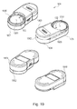
- Fig. 19 shows a schematic representation of the junction box, viewed from four different directions, according to another embodiment of the present invention.
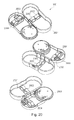
- Fig. 20 shows three further perspective views of the junction box 100 in the unfolded state according to an embodiment of the present invention.
- Fig. 21 shows the junction box in three further perspective views and with an I 2 C-bus cable and a connector according to an embodiment of the present invention.
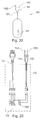
- Fig. 22 shows a schematic representation of a connection box according to an embodiment of the present invention.
- Fig. 23 shows a further schematic representation of a connection box according to an embodiment of the present invention.
- Fig. 1 shows a schematic representation of a first application of the connection box according to an embodiment of the present invention.
- the connection box 100 has a field device connection for connecting the box 100 to the field device 109.
- the connection of the box 100 to the field device 109 can take place, for example, directly on the field device or on the data cable 112, for example in the form of a tap 114.
- a connection cable 105 is provided (see Figs. 22 and 23 ).
- the data line 112 between the field device 109 and the evaluation and display device 111 is a so-called HART cable.
- the HART connection cable 105 for example, two plugs or terminals, via which a coupling to the data cable 112 is made possible.
- the evaluation / display unit 111 is arranged, for example, in the control room and serves u. a. the energy feed.
- An additional display device may be mounted on top of the field device 109. This is, for example, a so-called PLICSCOM device from VEGA.
- the tapping or coupling of the data line 112 can also be done on the power supply (parallel to the HART cable 112). Via the connecting line 105, a bidirectional data exchange is possible.
- the field device can thus be parameterized on the one hand. On the other hand, measured values can be read out.
- the connection to other field devices 110 is possible.
- the parameterization of the HART sensor 109 via the HART lines 112, 105 for example, with PACTware.
- PACTware is a manufacturer and fieldbus-independent software for operating field devices.
- the connection box 100 serves as a mechanical adapter between the HART line 112 and an operating unit 104.
- the operating unit 104 is, for example, a personal computer (PC), or else a laptop, a PDA, a mobile telephone, or other communication devices.
- the operating unit 104 may be the only operating unit or serve as an alternative to the device 111.
- a USB line 113 is provided, which connects the operating unit 104 with an interface adapter 103.
- the interface adapter 103 is attached to the interface connector 102 (see FIG Fig. 15 ) of the connection box.
- the measured value transmission can either be analog (ie 4..20mA) or digital in the so-called multi-drop method.
- Fig. 2 shows a second application of the junction box according to another embodiment of the present invention.
- the connection box 100 is connected directly to the field devices 109, 201 via corresponding I 2 C lines 202, 203.
- the device 201 is, for example, a field device to which the interface adapter 103 can not be mounted directly (for example, a series 50 device from VEGA).
- an adapter plug 108 (see Fig. 15 and 16 ) used.
- the adapter plug 108 allows the I 2 C line 203 of the connection box 100 to be coupled directly to the device connection of the series 50 device 201.
- an interface adapter can be placed directly on the field device interface to which the USB cable 113 is then inserted can.
- the interface adapter 103 is connected to the field device 201 via the connection box 100 and the I 2 C socket of the field device 201, for example.
- the length of the I 2 C cable 201 can be up to 25 m. Of course, the cable can also be made longer.
- FIG. 3 shows a third application of the junction box according to another embodiment of the present invention.
- a field device 109 is provided, which communicates via a HART line 112 with a supply and operating device 111.
- Several field devices can be connected in parallel to the supply and operating device 111 (for example, up to five field devices).
- the supply and operating device 111 has, for example, a so-called.
- PLC function memory-programmed control
- the device 111 is, for example, a MET from VEGA.
- the connection box 100 is connected to the supply and operating device 111 via the I 2 C line 202 and can be used on the one hand for parameterizing the supply and operating device 111 and on the other for accessing or interrogating the sensor 109.
- connection box 100 is connected via the interface adapter 103 and the USB line 113 to a laptop 104 or another communication device or input / output device.
- Fig. 4 shows a fourth application of the junction box according to another embodiment of the present invention.
- the connection box 100 is connected via an I 2 C line 202 to the level sensor 109.
- An indicating and operating device 401 is mounted directly on the connection box 100, that is to say connected to the interface connection 102. In this way, a remote, mobile operating unit is provided.
- a connection to a HART output of the field device 109 is possible.
- Fig. 5 shows a fifth application of the junction box according to another embodiment of the present invention.
- This is a wireless radio transmission for parameterizing the sensor 109.
- the sensor 109 is connected via the HART line 501 to a radio module 502, which is connected to a power supply 506 and thus supplies the sensor 109 with energy.
- the radio module can communicate wirelessly with a second radio module 503.
- the second radio module 503 also has a power supply 505 and is connected to the feed and control device 111 via a HART line 504.
- connection box 100 has, in addition to the interface adapter 103, a data cable 113, via which it is connected to the laptop 104. Furthermore, the connection box 100 has a radio interface 101 for the wireless transmission of signals between the box 100 and the field device 109. In this way, the radio link between the field device radio unit 502 and the operator or Ausense facilityen radio unit 503 can be accessed, for example, to parameterize the field device 109.
- Fig. 6 shows a sixth application of the junction box according to another embodiment of the present invention. Again, this is a wireless data transfer.
- the connection box 100 has an internal power supply in the form of a battery, a rechargeable battery or an external power supply.
- the connection to a PC or the like is not required because the connection box is connected to the display and adjustment module 401.
- Fig. 7 shows another application of the junction box according to an embodiment of the present invention.
- a radio module 702 is integrated in the sensor 109. Farther the sensor 109 is connected via supply line 701 to a supply device 111, for example via a HART line.
- the parameterization of the sensor 109 is carried out via radio with the help of the connection box 100, in which also a corresponding radio module is integrated.
- Fig. 8 shows another application of the junction box according to another embodiment of the present invention.
- a laptop 104 or the like is not required because the junction box 100 is coupled to the display and control unit 401.
- the power supply of the junction box is via battery or externally.
- a wireless module is installed both in the sensor and in the connection box 100.
- Fig. 9 shows a ninth application according to another embodiment of the invention.
- the connection box 100 is connected via the HART cable 105 to the HART line 112 between the power supply 111 and the sensor 109.
- the connection box 100 has an internal power supply, so that the analog measured value (analog current value) is not corrupted.
- the multi-drop mode can be used as an alternative to the analog measured value signal.
- no internal power supply of the connection box or the interface adapter 103 is necessary.
- the interface adapter 103 initiates the sensor data recording of the sensor 109.
- a storage medium is provided which is located either within the connection box 100 or is part of the interface adapter 103. Also, an external storage medium can be connected.
- sensor data can be recorded via the connection box 100.
- the data recording can be set up, for example, via a laptop 104 or an operator device 401 with regard to, for example, starting point, end point and recording interval.
- the recorded via the connection box 100 data can then be read out, for example via USB.
- Fig. 10 shows another application of the junction box according to another embodiment of the present invention.
- the interface adapter 103 is connected via an I 2 C line 202 to the sensor 109, which in turn is connected to a power supply 506.
- the interface adapter 103 initiates the sensor data tag.
- the interface adapter 103 is powered by the sensor.
- an internal or external storage medium is provided to record the sensor data. This may be, for example, a USB memory stick.
- the storage medium is integrated, for example, in the connection box or in the interface adapter 103.
- the recording via a laptop or the like 104 or via the HMI device 401 is set up. A readout of the recorded data takes place, for example, via the USB port of the interface adapter 103.
- Fig. 11 shows another application of the junction box according to another embodiment of the present invention.
- This is a radio transmission, as already in the Fig. 5 to 8 described.
- the interface adapter 103 is connected to the sensor 109 via a radio module mounted in the connection box 100 and the radio module 502.
- the interface adapter 103 initiates the sensor data recording and is powered by a battery, a battery or an external power supply. Again, an internal or external storage medium is provided to record the sensor data. Setting up the recording takes place as in the cases of Fig. 9 and 10 ,
- Fig. 12 shows another embodiment of a connection box application.
- the wireless communication between junction box 100 and sensor 109 is the same as in FIG Fig. 7 described case.
- the interface adapter 103 initiates the sensor data acquisition and is powered by a battery, a battery, or externally from a power supply 111.
- To record the sensor data is also here Storage medium integrated in the connection box or in the interface adapter 103 or connected externally.
- the laptop 104 or operating unit 401 is used to set up the data recording and to read the stored data.
- Fig. 13 shows another application of the junction box according to another embodiment of the present invention.
- the connection box 100 is designed such that to the interface port 102 (see Fig. 15 ) a combined control and communication unit 1401 can be connected.
- the combined operation and communication unit 1401 is a combination of an operation unit 401 and an interface adapter 103.
- Reference numeral 1402 shows the USB port.
- connection box 100 Through the combination of operating unit and communication unit, an operation or control of the sensor can be made from the connection box 100, while at the same time being able to connect the connection box to a laptop in order, for example, to read out data.
- Fig. 14 shows another application of the junction box according to another embodiment of the present invention.
- the connection box 100 has a second interface connection, to which the operating unit 401 can be connected, which can also be used for data storage.
- the measurement data can be temporarily stored in the operating unit 401, and subsequently a readout of the measurement data via the interface adapter 103 by the readout unit 104 can take place.
- Fig. 15 shows an adapter plug 108 according to an embodiment of the present invention in four different perspective views 1501, 1502, 1503, 1504.
- Fig. 16 shows the adapter plug the Fig. 15 in four further schematic representations.
- 1606 shows a front view
- 1607, 1608, 1609 show three side views of the adapter plug 108 (from above, from the side and from below)
- 1610 shows a rear view of the adapter plug 108.
- the adapter plug 108 has on the front side different contact areas 1602, 1603, 1604, 1605 for connection to a series 50 field device.
- a nose 1601 for example, is provided.
- 1610 shows a schematic representation of the adapter plug 108 in rear view.
- four connection areas 1703, 1704, 1705, 1706 are provided for connecting the adapter plug to an I 2 C plug of the I 2 C cable 202 of the connection box 100.
- an anti-rotation device is installed in the form of four dovetailed or otherwise shaped indentations 1701 on a first side and four curved bulges 1702 on a second side of the adapter plug 108.
- the bulges 1701, 1702 may also have other shapes, but must with corresponding indentations correspond to a Gegenbuchse.
- Fig. 17 shows three schematic representations of the interface terminal 102, 1901 with its spring contacts 1704, 1705, 1706, 1707, 1708 and 1709, 1710, 1711, 1712, 1713th
- the representation 1701 shows the underside of the interface connection 102, 1901, the representation 1702 shows a side view and 1703 shows a frontal view.
- the eight contact pins 1704 to 1713 are each provided with corresponding spring elements (not shown in FIG Fig. 17 ) coupled and can be at least partially pressed into the main body of the interface terminal 102 (against the spring forces). If now one Interface adapter 103 is screwed onto the connection box 100, the upper contact pins 1709 to 1713 are pressed against corresponding contact surfaces of the interface adapter 103, so that a good, electrically conductive contact is formed.
- Fig. 18 1801 shows a plan view of the contacts 1802, 1803, 1804, 1805.
- 1806 shows a top view of the contacts 1807, 1808, 1809, 1810.
- 1811 shows a first side view of the spring contacts and 1822 shows a second side view of the spring contacts with a 90 ° offset viewing direction.
- the spring contacts have, for example, spring elements, by means of which the contact pins 1802 to 1805 or 1807 to 1810 are pressed against the corresponding contact surfaces when the interface adapter 103 is screwed into the connection box 100.
- Fig. 19 shows a schematic representation 1907, 1908, 1909 of the connection box 100, viewed from four different directions.
- the connection box 100 has a connection region 1906 for receiving an interface adapter 103.
- interface connections 102, 1901 are provided, which are designed, for example, in the form of spring contacts.
- Interface terminals 102 serve to transmit an I 2 C signal
- the interface terminal 1901 (in combination with one of the interface terminals 102) serves to transmit a HART signal.
- the box 100 has a cable feedthrough 1902, through which the HART line 105 or the I 2 C-bus cable 106 can be guided.
- the box 100 has a cover element 1903 and a base element 1904, which are connected to one another via a hinge 1905, so that the box 100 can be unfolded.
- Fig. 20 shows three further perspective views 2007, 2008, 2009 of the connection box 100 in the unfolded state.
- Fig. 21 shows the junction box 100 in three further perspective views 2107, 2108, 2109 and with an I 2 C-bus cable 106 and a connector 108th
- a HART cable 105 (not shown in FIG Fig. 21 ), which exits for example from the socket 2101 and allows connection to a HART line of a field device.
- Fig. 22 shows a schematic representation of a connection box 100 according to another embodiment of the present invention.
- the connection box 100 has spring contacts 102 for connection to an interface adapter. A detailed illustration of the spring contacts 102 is shown in FIG Fig. 17 shown.
- the connection box 100 has a HART cable 105, which provides a field device connection 101.
- the HART cable 105 has two terminals 1501, 1502, which are formed for example in the form of terminals or plugs.
- the HART cable 105 can be connected to a field device via these two connections 1501, 1502.
- Fig. 23 shows a further schematic representation of a connection box 100 with a HART cable 105 with the two plugs 1501, 1502, and an I 2 C cable 106. Furthermore, the interface ports 102 and 1901 are provided.
Landscapes
- Physics & Mathematics (AREA)
- General Physics & Mathematics (AREA)
- Fluid Mechanics (AREA)
- Engineering & Computer Science (AREA)
- Signal Processing (AREA)
- Arrangements For Transmission Of Measured Signals (AREA)
- Measuring Fluid Pressure (AREA)
Priority Applications (1)
| Application Number | Priority Date | Filing Date | Title |
|---|---|---|---|
| EP15173857.2A EP2944927A1 (fr) | 2006-11-27 | 2007-11-06 | Boitier de raccordement |
Applications Claiming Priority (6)
| Application Number | Priority Date | Filing Date | Title |
|---|---|---|---|
| US86123406P | 2006-11-27 | 2006-11-27 | |
| US86123306P | 2006-11-27 | 2006-11-27 | |
| US86123206P | 2006-11-27 | 2006-11-27 | |
| DE200610055897 DE102006055897B4 (de) | 2005-12-27 | 2006-11-27 | Anschlussbox |
| DE200610055898 DE102006055898B4 (de) | 2005-12-27 | 2006-11-27 | Anschlussbox |
| DE200610055900 DE102006055900B4 (de) | 2005-12-27 | 2006-11-27 | Schnittstellenadapter |
Related Child Applications (2)
| Application Number | Title | Priority Date | Filing Date |
|---|---|---|---|
| EP15173857.2A Division EP2944927A1 (fr) | 2006-11-27 | 2007-11-06 | Boitier de raccordement |
| EP15173857.2A Division-Into EP2944927A1 (fr) | 2006-11-27 | 2007-11-06 | Boitier de raccordement |
Publications (3)
| Publication Number | Publication Date |
|---|---|
| EP1926068A2 true EP1926068A2 (fr) | 2008-05-28 |
| EP1926068A3 EP1926068A3 (fr) | 2009-01-21 |
| EP1926068B1 EP1926068B1 (fr) | 2015-08-19 |
Family
ID=39092886
Family Applications (4)
| Application Number | Title | Priority Date | Filing Date |
|---|---|---|---|
| EP07119890A Ceased EP1925918A3 (fr) | 2006-11-27 | 2007-11-02 | Boite de connection pour la transmission d'un signal |
| EP07120088.5A Ceased EP1926068B1 (fr) | 2006-11-27 | 2007-11-06 | Appareil et procédé de traitement de caractères |
| EP15173857.2A Ceased EP2944927A1 (fr) | 2006-11-27 | 2007-11-06 | Boitier de raccordement |
| EP07120077A Withdrawn EP1950536A3 (fr) | 2006-11-27 | 2007-11-06 | Adaptateur d'interface |
Family Applications Before (1)
| Application Number | Title | Priority Date | Filing Date |
|---|---|---|---|
| EP07119890A Ceased EP1925918A3 (fr) | 2006-11-27 | 2007-11-02 | Boite de connection pour la transmission d'un signal |
Family Applications After (2)
| Application Number | Title | Priority Date | Filing Date |
|---|---|---|---|
| EP15173857.2A Ceased EP2944927A1 (fr) | 2006-11-27 | 2007-11-06 | Boitier de raccordement |
| EP07120077A Withdrawn EP1950536A3 (fr) | 2006-11-27 | 2007-11-06 | Adaptateur d'interface |
Country Status (3)
| Country | Link |
|---|---|
| US (3) | US20080126005A1 (fr) |
| EP (4) | EP1925918A3 (fr) |
| CN (3) | CN101221688B (fr) |
Cited By (2)
| Publication number | Priority date | Publication date | Assignee | Title |
|---|---|---|---|---|
| DE102018117175A1 (de) * | 2018-07-16 | 2020-01-16 | Vega Grieshaber Kg | Verbindungsvorrichtung zwischen Feldgerät und Vor-Ort-Anzeige |
| US11976955B2 (en) | 2018-09-21 | 2024-05-07 | Ecolab Usa Inc. | Portable fluid level monitoring device and method |
Families Citing this family (53)
| Publication number | Priority date | Publication date | Assignee | Title |
|---|---|---|---|---|
| US8538560B2 (en) * | 2004-04-29 | 2013-09-17 | Rosemount Inc. | Wireless power and communication unit for process field devices |
| US8725081B2 (en) * | 2007-04-13 | 2014-05-13 | Fisher-Rosemount Systems, Inc. | Wireless process communication adapter for handheld field maintenance tool |
| DE102007029136A1 (de) * | 2007-06-25 | 2009-01-02 | Vega Grieshaber Kg | Vorrichtung und Verfahren zum Generieren einer Bedienoberflächenkonfiguration für ein Feldgerät |
| EP2096505A1 (fr) * | 2008-02-26 | 2009-09-02 | ABB Research Ltd. | Procédé, produits et système pour la configuration d'un nouveau noed dans un réseau sans fil industriel |
| DE102009024853A1 (de) * | 2008-06-12 | 2009-12-17 | Abb Technology Ag | Fernmesstechnische Einrichtung mit einem schleifengespeisten Gerät und Verfahren zu dessen Betriebsspannungsversorgung |
| US8929948B2 (en) | 2008-06-17 | 2015-01-06 | Rosemount Inc. | Wireless communication adapter for field devices |
| CN102084307B (zh) * | 2008-06-17 | 2014-10-29 | 罗斯蒙特公司 | 用于具有低压本质安全钳的现场设备的rf适配器 |
| CN102067048B (zh) * | 2008-06-17 | 2017-03-08 | 罗斯蒙特公司 | 用于具有可变压降的现场设备的rf适配器 |
| US8694060B2 (en) | 2008-06-17 | 2014-04-08 | Rosemount Inc. | Form factor and electromagnetic interference protection for process device wireless adapters |
| DE102008036554A1 (de) * | 2008-08-06 | 2010-02-11 | Endress + Hauser Process Solutions Ag | Autarkes Feldgerät oder autarker Funkadapter für ein Feldgerät der Automatisierungstechnik |
| DE102008036967A1 (de) * | 2008-08-08 | 2010-02-11 | Endress + Hauser Process Solutions Ag | Universelle Schnittstelle für einen Wireless Adapter |
| DE102008037195A1 (de) * | 2008-08-11 | 2010-02-18 | Endress + Hauser Process Solutions Ag | Vorrichtung zum Bedienen eines Feldgeräts, das in ein Funknetzwerk der Automatisierungstechnik eingebunden ist |
| CN101726389B (zh) * | 2008-10-31 | 2011-04-20 | 沈阳仪表科学研究院 | 硅电容智能压力/差压变送器及其测量方法 |
| EP2239955B1 (fr) * | 2009-04-09 | 2016-07-06 | VEGA Grieshaber KG | Transmission de données commandée par l'énergie d'un appareil de terrain |
| EP2430503B1 (fr) * | 2009-05-15 | 2017-11-22 | Fisher-Rosemount Systems, Inc. | Méthode d'évaluation d'un emplacement potentiel pour ajouter un appareil de terrain sans fil dans un réseau existant |
| JP2012527055A (ja) * | 2009-05-15 | 2012-11-01 | フィッシャー−ローズマウント・システムズ・インコーポレーテッド | 改良された機能性を備えた手持ち式フィールドメンテナンスツール |
| US9674976B2 (en) * | 2009-06-16 | 2017-06-06 | Rosemount Inc. | Wireless process communication adapter with improved encapsulation |
| US8626087B2 (en) * | 2009-06-16 | 2014-01-07 | Rosemount Inc. | Wire harness for field devices used in a hazardous locations |
| DE102009045863A1 (de) * | 2009-10-20 | 2011-04-21 | Endress + Hauser Process Solutions Ag | Aufzeichnung und Wiedergabe von Dienstsequenzen |
| DE102009055247A1 (de) * | 2009-12-23 | 2011-06-30 | Endress + Hauser Conducta Gesellschaft für Mess- und Regeltechnik mbH + Co. KG, 70839 | Anordnung mit einer übergeordneten Steuereinheit und zumindest einem mit der Steuereinheit verbindbaren intelligenten Feldgerät |
| US20120041744A1 (en) | 2010-07-28 | 2012-02-16 | Kantzes Christopher P | Handheld field maintenance tool with field device simulation capability |
| US10761524B2 (en) | 2010-08-12 | 2020-09-01 | Rosemount Inc. | Wireless adapter with process diagnostics |
| US20120054389A1 (en) * | 2010-08-26 | 2012-03-01 | Research In Motion Limited | USB To I2C And SPI Bridge |
| US9310794B2 (en) | 2011-10-27 | 2016-04-12 | Rosemount Inc. | Power supply for industrial process field device |
| CN102567270A (zh) * | 2011-12-05 | 2012-07-11 | 深圳市金凯博自动化测试有限公司 | 一种usb转i2c适配器 |
| EP2762839B1 (fr) * | 2013-01-30 | 2016-11-02 | VEGA Grieshaber KG | Dispositif d'adaptateur doté d'une interface mécanique pour un boîtier d'appareil de mesure |
| EP4280710A3 (fr) * | 2013-08-09 | 2024-03-13 | EnOcean GmbH | Procédé de détermination d'un canal de réception approprié d'un système récepteur et système récepteur correspondant |
| US9785595B2 (en) | 2013-09-09 | 2017-10-10 | Lenovo Enterprise Solutions (Singapore) Pte. Ltd. | Multi-channel universal serial bus (USB) to subrate channel systems |
| WO2016000260A1 (fr) * | 2014-07-04 | 2016-01-07 | Abb Technology Ltd | Dispositif d'automatisation autonome et machine |
| GB201520985D0 (en) * | 2015-11-27 | 2016-01-13 | Saville Andrew | System for and method for monitoring a hydration pack |
| AT517608B1 (de) * | 2016-01-21 | 2017-03-15 | Avl List Gmbh | Elektronikeinheit für ein Durchflussmessgerät |
| US10382312B2 (en) | 2016-03-02 | 2019-08-13 | Fisher-Rosemount Systems, Inc. | Detecting and locating process control communication line faults from a handheld maintenance tool |
| US11605037B2 (en) | 2016-07-20 | 2023-03-14 | Fisher-Rosemount Systems, Inc. | Fleet management system for portable maintenance tools |
| US10554644B2 (en) | 2016-07-20 | 2020-02-04 | Fisher-Rosemount Systems, Inc. | Two-factor authentication for user interface devices in a process plant |
| US10599134B2 (en) * | 2016-07-22 | 2020-03-24 | Fisher-Rosemount Systems, Inc. | Portable field maintenance tool configured for multiple process control communication protocols |
| US10374873B2 (en) | 2016-07-22 | 2019-08-06 | Fisher-Rosemount Systems, Inc. | Process control communication between a portable field maintenance tool and a process control instrument |
| US10375162B2 (en) | 2016-07-22 | 2019-08-06 | Fisher-Rosemount Systems, Inc. | Process control communication architecture |
| US10270853B2 (en) | 2016-07-22 | 2019-04-23 | Fisher-Rosemount Systems, Inc. | Process control communication between a portable field maintenance tool and an asset management system |
| US10585422B2 (en) * | 2016-07-22 | 2020-03-10 | Fisher-Rosemount Systems, Inc. | Portable field maintenance tool system having interchangeable functional modules |
| US10481627B2 (en) | 2016-07-25 | 2019-11-19 | Fisher-Rosemount Systems, Inc. | Connection check in field maintenance tool |
| US10505585B2 (en) | 2016-07-25 | 2019-12-10 | Fisher-Rosemount Systems, Inc. | Portable field maintenance tool with a bus for powering and communicating with a field device |
| US10764083B2 (en) | 2016-07-25 | 2020-09-01 | Fisher-Rosemount Systems, Inc. | Portable field maintenance tool with resistor network for intrinsically safe operation |
| DE102016125239A1 (de) * | 2016-12-21 | 2018-06-21 | Endress+Hauser SE+Co. KG | System der Automatisierungstechnik |
| DE102017103554B3 (de) | 2017-02-21 | 2018-05-09 | Phoenix Contact Gmbh & Co. Kg | Frontadapter zum Verbinden mit einer Steuerungseinrichtung und Automatisierungssystem |
| US10422684B2 (en) | 2017-05-30 | 2019-09-24 | Rosemount Tank Radar Ab | Field device with second auxiliary interface |
| US10461562B2 (en) | 2017-06-27 | 2019-10-29 | Rosemount Inc. | Field device charging power regulation |
| EP3598082A1 (fr) | 2018-07-20 | 2020-01-22 | VEGA Grieshaber KG | Dispositif de mesure pourvu de dispositif d'interaction de champ proche |
| DE102018129491A1 (de) * | 2018-11-22 | 2020-05-28 | Endress+Hauser SE+Co. KG | Feldgeräteadapter zur drahtlosen Datenübertragung |
| CN110046110A (zh) * | 2019-04-24 | 2019-07-23 | 嘉应学院 | 一种用于现场设置终端的方法及适配器 |
| US11888255B2 (en) | 2019-07-15 | 2024-01-30 | Panduit Corp. | Single pair ethernet connector |
| USD928094S1 (en) * | 2019-12-19 | 2021-08-17 | Tang Yang Dies Co. Ltd. | Motorcycle USB type c charger |
| EP3910298B1 (fr) * | 2020-05-15 | 2022-05-04 | VEGA Grieshaber KG | Module d'affichage et de commande amovible pour un appareil de terrain |
| EP4163605A1 (fr) * | 2021-10-07 | 2023-04-12 | VEGA Grieshaber KG | Appareil de terrain pourvu d'affichage consolidé |
Citations (1)
| Publication number | Priority date | Publication date | Assignee | Title |
|---|---|---|---|---|
| EP1293853A1 (fr) | 2001-09-12 | 2003-03-19 | ENDRESS + HAUSER WETZER GmbH + Co. KG | Module transmetteur pour un dispositif sur site |
Family Cites Families (37)
| Publication number | Priority date | Publication date | Assignee | Title |
|---|---|---|---|---|
| AT6011B (fr) | 1899-07-08 | 1901-12-10 | Maschb Anstalt Fuer Kabelfabri | |
| US4398265A (en) * | 1980-09-15 | 1983-08-09 | Motorola, Inc. | Keyboard and display interface adapter architecture |
| US5361200A (en) * | 1992-09-02 | 1994-11-01 | Parker Marketing Research, Inc. | Real time data collection system |
| GB2290631B (en) | 1994-06-24 | 1998-11-11 | Fuji Heavy Ind Ltd | Diagnosis system for motor vehicle and the method thereof |
| ATE187824T1 (de) * | 1994-10-24 | 2000-01-15 | Fisher Rosemount Systems Inc | Vorrichtung, die einen zugang zu feldgeräten in einem verteilten steuerungssystem gestattet |
| US6304934B1 (en) * | 1995-10-13 | 2001-10-16 | Smar Research Corporation | Computer to fieldbus control system interface |
| US6285966B1 (en) | 1998-06-25 | 2001-09-04 | Fisher Controls International, Inc. | Function block apparatus for viewing data in a process control system |
| US6738856B1 (en) | 1999-01-19 | 2004-05-18 | Sequel Imaging, Inc | External display peripheral for coupling to a universal serial bus port or hub on a computer |
| DE10052836A1 (de) | 2000-10-24 | 2002-05-16 | Endress Hauser Gmbh Co | Vorrichtung zur Bestimmung und/oder Überwachung einer Prozeßvariablen |
| US6906638B2 (en) * | 2000-11-17 | 2005-06-14 | Vega Grieshaber Kg | Sensor unit |
| DE50002284D1 (de) * | 2000-11-30 | 2003-06-26 | Siemens Building Tech Ag | Anordnung zur Überwachung, Steuerung und Regelung einer betriebstechnischen Anlage eines Gebäudes |
| KR100419196B1 (ko) * | 2001-07-06 | 2004-02-19 | 삼성전자주식회사 | 필드버스 인터페이스 보드 |
| DE10144971A1 (de) | 2001-09-12 | 2003-03-27 | Endress & Hauser Gmbh & Co Kg | Verfahren zur Sicherung des Datenaustauschs zwischen einer externen Zugriffseinheit und einem Feldgerät |
| JP2003151712A (ja) * | 2001-11-14 | 2003-05-23 | Yazaki Corp | スリップリング装置 |
| DE60207106T2 (de) * | 2001-12-06 | 2006-07-13 | Fisher-Rosemount Systems, Inc., Austin | Eigensicheres feldgerätwartungs-werkzeug |
| TW563954U (en) * | 2002-05-09 | 2003-11-21 | Yue-Yun Huang | Cable storage box with serial connection |
| EP1529198B1 (fr) * | 2002-08-13 | 2020-02-26 | VEGA Grieshaber KG | Systeme pour realiser un dispositif de structure modulaire qui sert a determiner une grandeur de processus physique, et composants normalises |
| DE10332392B4 (de) * | 2002-09-10 | 2014-12-04 | Sew-Eurodrive Gmbh & Co Kg | Feldgerät mit einem Gehäuse |
| CN1403931A (zh) * | 2002-10-17 | 2003-03-19 | 武汉市工程科学技术研究院自动化研究所 | 便携式现场总线型表决系统 |
| DE10260959A1 (de) * | 2002-12-20 | 2004-07-15 | Endress + Hauser Gmbh + Co. Kg | Füllstandsmeßgerät und Verfahren zur Füllstandsmessung |
| US6783856B1 (en) * | 2003-04-07 | 2004-08-31 | Ensci Inc | Metal oxyanion coated porous substrates |
| CN2638123Y (zh) * | 2003-06-17 | 2004-09-01 | 上海亨井联接件有限公司 | 一种旋转式适配器 |
| US7460865B2 (en) * | 2003-06-18 | 2008-12-02 | Fisher-Rosemount Systems, Inc. | Self-configuring communication networks for use with process control systems |
| US20050088307A1 (en) * | 2003-10-14 | 2005-04-28 | Schaffer Joseph W. | Transmitter |
| JP3830935B2 (ja) * | 2003-10-29 | 2006-10-11 | シャープ株式会社 | 携帯型電源 |
| DE102004020393A1 (de) * | 2004-04-23 | 2005-11-10 | Endress + Hauser Gmbh + Co. Kg | Funkmodul für Feldgeräte der Automatisierungstechnik |
| US8538560B2 (en) * | 2004-04-29 | 2013-09-17 | Rosemount Inc. | Wireless power and communication unit for process field devices |
| US7262693B2 (en) * | 2004-06-28 | 2007-08-28 | Rosemount Inc. | Process field device with radio frequency communication |
| DE102004055308A1 (de) * | 2004-11-16 | 2006-05-18 | Endress + Hauser Flowtec Ag | Funkeinheit für ein Feldgerät der Automatisierungstechnik |
| US7421531B2 (en) * | 2005-01-12 | 2008-09-02 | Rosemount Inc. | Isolating system that couples fieldbus data to a network |
| RU2405269C2 (ru) * | 2005-02-24 | 2010-11-27 | Фега Грисхабер Кг | Система полевой шины для беспроводной связи |
| DE102005008488B4 (de) * | 2005-02-24 | 2011-08-18 | VEGA Grieshaber KG, 77709 | Datenübertragungssystem zur drahtlosen Kommunikation |
| US7189106B2 (en) * | 2005-05-17 | 2007-03-13 | Young Eric D | Electric adapter organizer |
| US8112565B2 (en) * | 2005-06-08 | 2012-02-07 | Fisher-Rosemount Systems, Inc. | Multi-protocol field device interface with automatic bus detection |
| DE102005062421A1 (de) * | 2005-12-27 | 2007-06-28 | Vega Grieshaber Kg | Heizeinrichtung für ein Feldgerätedisplay |
| US7376537B2 (en) * | 2006-08-31 | 2008-05-20 | Delory Jr Paul A | Integrated portable electronics tester |
| US7675932B2 (en) * | 2006-11-09 | 2010-03-09 | Rosemount Inc. | Adapter for providing digital communication between a field device and a computer |
-
2007
- 2007-11-02 EP EP07119890A patent/EP1925918A3/fr not_active Ceased
- 2007-11-06 US US11/935,689 patent/US20080126005A1/en not_active Abandoned
- 2007-11-06 US US11/935,702 patent/US20090193169A9/en not_active Abandoned
- 2007-11-06 US US11/935,667 patent/US8150462B2/en not_active Expired - Fee Related
- 2007-11-06 EP EP07120088.5A patent/EP1926068B1/fr not_active Ceased
- 2007-11-06 EP EP15173857.2A patent/EP2944927A1/fr not_active Ceased
- 2007-11-06 EP EP07120077A patent/EP1950536A3/fr not_active Withdrawn
- 2007-11-26 CN CN2007101673780A patent/CN101221688B/zh not_active Expired - Fee Related
- 2007-11-26 CN CNA2007101673808A patent/CN101221691A/zh active Pending
- 2007-11-26 CN CN2007101673812A patent/CN101192334B/zh active Active
Patent Citations (1)
| Publication number | Priority date | Publication date | Assignee | Title |
|---|---|---|---|---|
| EP1293853A1 (fr) | 2001-09-12 | 2003-03-19 | ENDRESS + HAUSER WETZER GmbH + Co. KG | Module transmetteur pour un dispositif sur site |
Cited By (2)
| Publication number | Priority date | Publication date | Assignee | Title |
|---|---|---|---|---|
| DE102018117175A1 (de) * | 2018-07-16 | 2020-01-16 | Vega Grieshaber Kg | Verbindungsvorrichtung zwischen Feldgerät und Vor-Ort-Anzeige |
| US11976955B2 (en) | 2018-09-21 | 2024-05-07 | Ecolab Usa Inc. | Portable fluid level monitoring device and method |
Also Published As
| Publication number | Publication date |
|---|---|
| EP2944927A1 (fr) | 2015-11-18 |
| EP1925918A3 (fr) | 2009-01-21 |
| CN101192334A (zh) | 2008-06-04 |
| US20080183935A1 (en) | 2008-07-31 |
| CN101192334B (zh) | 2011-11-16 |
| US20090193169A9 (en) | 2009-07-30 |
| US20080125175A1 (en) | 2008-05-29 |
| EP1925918A2 (fr) | 2008-05-28 |
| CN101221691A (zh) | 2008-07-16 |
| CN101221688A (zh) | 2008-07-16 |
| US8150462B2 (en) | 2012-04-03 |
| EP1926068A3 (fr) | 2009-01-21 |
| EP1950536A2 (fr) | 2008-07-30 |
| EP1926068B1 (fr) | 2015-08-19 |
| CN101221688B (zh) | 2013-05-08 |
| US20080126005A1 (en) | 2008-05-29 |
| EP1950536A3 (fr) | 2009-01-21 |
Similar Documents
| Publication | Publication Date | Title |
|---|---|---|
| EP1926068B1 (fr) | Appareil et procédé de traitement de caractères | |
| DE102006055897B4 (de) | Anschlussbox | |
| DE102009022762A1 (de) | Zweikammergehäuse für ein Feldgerät | |
| EP2145373B1 (fr) | Dispositif et système de reconnaissance de batterie | |
| DE102013111714A1 (de) | Verfahren zur Funktionseinstellung einer Messstelle und Messstelle | |
| DE102019101883A1 (de) | Sensoreinrichtung für eine Reihenklemmenanordnung, Reihenklemmenanordnung, Reihenklemme, Schaltschrank sowie Ausleseeinrichtung | |
| WO2017060018A1 (fr) | Appareil de terrain de structure modulaire comprenant un appareil d'affichage/de commande qui comprend un module radio et une alimentation en énergie interne | |
| EP4115246B1 (fr) | Adaptateur pour appareil de terrain pour la transmission sans fil de données | |
| EP2650740A1 (fr) | Procédé de création d'un état de réception temporaire d'un appareil de terrain et système de mesure | |
| DE102019134197A1 (de) | Feldgerät, Inbetriebnahmesystem und Verfahren zur Inbetriebnahme eines Feldgeräts | |
| EP3545267A1 (fr) | Adaptateur de communication pour un transmetteur d'un appareil de terrain | |
| AT15721U1 (de) | Kommunikationseinheit sowie System umfassend die Kommunikationseinheit | |
| EP1932250B1 (fr) | Enregistreur de donnees pour appareil de mesure | |
| EP4388285A1 (fr) | Dispositif de terrain modulaire | |
| WO2017041988A1 (fr) | Procédé pour garantir le fonctionnement d'un module sans fil d'un appareil de terrain | |
| EP3837590B1 (fr) | Appareil de terrain de la technique de l'automatisation | |
| EP3433905B1 (fr) | Couvercle de boîtier pour appareil de terrain pour transmission sans fil d'informations | |
| DE102018122014A1 (de) | Meßgeräte-System sowie damit gebildete Meßanordnung | |
| EP2508839A1 (fr) | Dispositif de mesure doté d'une commutation d'émission pour la transmission sans fil d'un signal d'émission de valeur de mesure | |
| DE102021128111A1 (de) | Ladekabel und verfahren zum betreiben desselben | |
| DE102019100513B4 (de) | Datenlogger, Baureihe und Netzwerk | |
| EP3108568A1 (fr) | Module de commande, relevé et/ou surveillance à distance d'appareils électriques | |
| WO2022100821A1 (fr) | Interface fonctionnelle pour la fourniture d'une fonction en fonction de valeurs de mesure de capteur, et capteur pour la fourniture de valeurs de mesure à une interface fonctionnelle | |
| DE102008030908B4 (de) | Datenspeicherschaltung mit integrierter Datenspeichereinheit für einen Sensor mit physikalisch-elektrischem Wandler | |
| EP4526055A1 (fr) | Dispositif ultrasonore modulaire, système ultrasonore et procédé de modification d'un dispositif ultrasonore modulaire |
Legal Events
| Date | Code | Title | Description |
|---|---|---|---|
| PUAI | Public reference made under article 153(3) epc to a published international application that has entered the european phase |
Free format text: ORIGINAL CODE: 0009012 |
|
| AK | Designated contracting states |
Kind code of ref document: A2 Designated state(s): AT BE BG CH CY CZ DE DK EE ES FI FR GB GR HU IE IS IT LI LT LU LV MC MT NL PL PT RO SE SI SK TR |
|
| AX | Request for extension of the european patent |
Extension state: AL BA HR MK RS |
|
| PUAL | Search report despatched |
Free format text: ORIGINAL CODE: 0009013 |
|
| AK | Designated contracting states |
Kind code of ref document: A3 Designated state(s): AT BE BG CH CY CZ DE DK EE ES FI FR GB GR HU IE IS IT LI LT LU LV MC MT NL PL PT RO SE SI SK TR |
|
| AX | Request for extension of the european patent |
Extension state: AL BA HR MK RS |
|
| RIC1 | Information provided on ipc code assigned before grant |
Ipc: G01L 11/00 20060101ALI20081215BHEP Ipc: G01F 23/00 20060101AFI20081215BHEP Ipc: G01L 9/00 20060101ALI20081215BHEP |
|
| 17P | Request for examination filed |
Effective date: 20090618 |
|
| AKX | Designation fees paid |
Designated state(s): DE FR GB |
|
| 17Q | First examination report despatched |
Effective date: 20100521 |
|
| GRAP | Despatch of communication of intention to grant a patent |
Free format text: ORIGINAL CODE: EPIDOSNIGR1 |
|
| INTG | Intention to grant announced |
Effective date: 20150413 |
|
| GRAS | Grant fee paid |
Free format text: ORIGINAL CODE: EPIDOSNIGR3 |
|
| GRAA | (expected) grant |
Free format text: ORIGINAL CODE: 0009210 |
|
| AK | Designated contracting states |
Kind code of ref document: B1 Designated state(s): DE FR GB |
|
| REG | Reference to a national code |
Ref country code: GB Ref legal event code: FG4D Free format text: NOT ENGLISH |
|
| REG | Reference to a national code |
Ref country code: DE Ref legal event code: R096 Ref document number: 502007014157 Country of ref document: DE |
|
| REG | Reference to a national code |
Ref country code: FR Ref legal event code: PLFP Year of fee payment: 9 |
|
| REG | Reference to a national code |
Ref country code: DE Ref legal event code: R097 Ref document number: 502007014157 Country of ref document: DE |
|
| PLBE | No opposition filed within time limit |
Free format text: ORIGINAL CODE: 0009261 |
|
| STAA | Information on the status of an ep patent application or granted ep patent |
Free format text: STATUS: NO OPPOSITION FILED WITHIN TIME LIMIT |
|
| 26N | No opposition filed |
Effective date: 20160520 |
|
| REG | Reference to a national code |
Ref country code: FR Ref legal event code: PLFP Year of fee payment: 10 |
|
| REG | Reference to a national code |
Ref country code: FR Ref legal event code: PLFP Year of fee payment: 11 |
|
| PGFP | Annual fee paid to national office [announced via postgrant information from national office to epo] |
Ref country code: DE Payment date: 20211122 Year of fee payment: 15 Ref country code: GB Payment date: 20211123 Year of fee payment: 15 Ref country code: FR Payment date: 20211119 Year of fee payment: 15 |
|
| REG | Reference to a national code |
Ref country code: DE Ref legal event code: R119 Ref document number: 502007014157 Country of ref document: DE |
|
| P01 | Opt-out of the competence of the unified patent court (upc) registered |
Effective date: 20230428 |
|
| GBPC | Gb: european patent ceased through non-payment of renewal fee |
Effective date: 20221106 |
|
| PG25 | Lapsed in a contracting state [announced via postgrant information from national office to epo] |
Ref country code: GB Free format text: LAPSE BECAUSE OF NON-PAYMENT OF DUE FEES Effective date: 20221106 Ref country code: DE Free format text: LAPSE BECAUSE OF NON-PAYMENT OF DUE FEES Effective date: 20230601 |
|
| PG25 | Lapsed in a contracting state [announced via postgrant information from national office to epo] |
Ref country code: FR Free format text: LAPSE BECAUSE OF NON-PAYMENT OF DUE FEES Effective date: 20221130 |