EP1926083A1 - Audiocodierungsgerät und audiocodierungsmethode - Google Patents
Audiocodierungsgerät und audiocodierungsmethode Download PDFInfo
- Publication number
- EP1926083A1 EP1926083A1 EP06810844A EP06810844A EP1926083A1 EP 1926083 A1 EP1926083 A1 EP 1926083A1 EP 06810844 A EP06810844 A EP 06810844A EP 06810844 A EP06810844 A EP 06810844A EP 1926083 A1 EP1926083 A1 EP 1926083A1
- Authority
- EP
- European Patent Office
- Prior art keywords
- section
- spectrum
- encoding
- layer
- speech
- Prior art date
- Legal status (The legal status is an assumption and is not a legal conclusion. Google has not performed a legal analysis and makes no representation as to the accuracy of the status listed.)
- Withdrawn
Links
Images










Classifications
-
- G—PHYSICS
- G10—MUSICAL INSTRUMENTS; ACOUSTICS
- G10L—SPEECH ANALYSIS TECHNIQUES OR SPEECH SYNTHESIS; SPEECH RECOGNITION; SPEECH OR VOICE PROCESSING TECHNIQUES; SPEECH OR AUDIO CODING OR DECODING
- G10L19/00—Speech or audio signals analysis-synthesis techniques for redundancy reduction, e.g. in vocoders; Coding or decoding of speech or audio signals, using source filter models or psychoacoustic analysis
- G10L19/04—Speech or audio signals analysis-synthesis techniques for redundancy reduction, e.g. in vocoders; Coding or decoding of speech or audio signals, using source filter models or psychoacoustic analysis using predictive techniques
- G10L19/06—Determination or coding of the spectral characteristics, e.g. of the short-term prediction coefficients
-
- G—PHYSICS
- G10—MUSICAL INSTRUMENTS; ACOUSTICS
- G10L—SPEECH ANALYSIS TECHNIQUES OR SPEECH SYNTHESIS; SPEECH RECOGNITION; SPEECH OR VOICE PROCESSING TECHNIQUES; SPEECH OR AUDIO CODING OR DECODING
- G10L21/00—Speech or voice signal processing techniques to produce another audible or non-audible signal, e.g. visual or tactile, in order to modify its quality or its intelligibility
- G10L21/02—Speech enhancement, e.g. noise reduction or echo cancellation
- G10L21/038—Speech enhancement, e.g. noise reduction or echo cancellation using band spreading techniques
-
- G—PHYSICS
- G10—MUSICAL INSTRUMENTS; ACOUSTICS
- G10L—SPEECH ANALYSIS TECHNIQUES OR SPEECH SYNTHESIS; SPEECH RECOGNITION; SPEECH OR VOICE PROCESSING TECHNIQUES; SPEECH OR AUDIO CODING OR DECODING
- G10L19/00—Speech or audio signals analysis-synthesis techniques for redundancy reduction, e.g. in vocoders; Coding or decoding of speech or audio signals, using source filter models or psychoacoustic analysis
- G10L19/04—Speech or audio signals analysis-synthesis techniques for redundancy reduction, e.g. in vocoders; Coding or decoding of speech or audio signals, using source filter models or psychoacoustic analysis using predictive techniques
-
- G—PHYSICS
- G10—MUSICAL INSTRUMENTS; ACOUSTICS
- G10L—SPEECH ANALYSIS TECHNIQUES OR SPEECH SYNTHESIS; SPEECH RECOGNITION; SPEECH OR VOICE PROCESSING TECHNIQUES; SPEECH OR AUDIO CODING OR DECODING
- G10L19/00—Speech or audio signals analysis-synthesis techniques for redundancy reduction, e.g. in vocoders; Coding or decoding of speech or audio signals, using source filter models or psychoacoustic analysis
- G10L19/04—Speech or audio signals analysis-synthesis techniques for redundancy reduction, e.g. in vocoders; Coding or decoding of speech or audio signals, using source filter models or psychoacoustic analysis using predictive techniques
- G10L19/16—Vocoder architecture
- G10L19/18—Vocoders using multiple modes
- G10L19/24—Variable rate codecs, e.g. for generating different qualities using a scalable representation such as hierarchical encoding or layered encoding
-
- G—PHYSICS
- G10—MUSICAL INSTRUMENTS; ACOUSTICS
- G10L—SPEECH ANALYSIS TECHNIQUES OR SPEECH SYNTHESIS; SPEECH RECOGNITION; SPEECH OR VOICE PROCESSING TECHNIQUES; SPEECH OR AUDIO CODING OR DECODING
- G10L21/00—Speech or voice signal processing techniques to produce another audible or non-audible signal, e.g. visual or tactile, in order to modify its quality or its intelligibility
- G10L21/02—Speech enhancement, e.g. noise reduction or echo cancellation
Definitions
- the present invention relates to a speech encoding apparatus and speech encoding method.
- a mobile communication system is required to compress a speech signal to a low bit rate for effective use of radio resources.
- this technique refers to integrating in layers the first layer where an input signal according to a model suitable for a speech signal is encoded at a low bit rate and the second layer where an differential signal between the--input signal and the first layer decoded signal is encoded according to a model suitable for signals other than speech.
- An encoding scheme with such a layered structure includes features that, even if a portion of an encoded bit stream is discarded, the decoded signal can be obtained from the rest of information, that is, scalability, and so is referred to as "scalable encoding.” Based on these features, scalable encoding can flexibly support communication between networks of different bit rates. Further, these features are suitable for the network environment in the future where various networks are integrated through the IP protocol.
- Some conventional scalable encoding employs a standardized technique with MPEG-4 (Moving Picture Experts Group phase-4) (for example, see Non-Patent Document 1).
- CELP code excited linear prediction
- AAC advanced audio coder
- TwinVQ transform domain weighted interleave vector quantization
- Patent Document 1 there is a technique for encoding a spectrum efficiently (for example, see Patent Document 1).
- the technique disclosed in Patent Document 1 refers to dividing the frequency band of a speech signal into two subbands of a low band and a high band, duplicating the low band spectrum to the high band and obtaining the high band spectrum by modifying the duplicated spectrum. In this case, it is possible realize lower bit rate by encoding modification information with a small number of bits.
- Non-Patent Document 1 " Everything about MPEG-4" (MPEG-4 no subete), the first edition, written and edited by Sukeichi MIKI, Kogyo Chosakai Publishing, Inc., September 30, 1998, page 126 to 127 .
- Patent Document Japanese translation of a PCT Application Laid-Open No.2001-521648
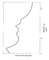
- the spectrum of a speech signal or an audio signal is represented by the product of the component (spectral envelope) that changes moderately with the frequency and the component (spectral fine structure) that shows rapid changes.
- FIG.1 shows the spectrum of a speech signal
- FIG.2 shows the spectral envelope
- FIG.3 shows the spectral fine structure.
- This spectral envelope ( FIG.2 ) is calculated using LPC (Linear Prediction Coding) coefficients of order ten.
- the product of the spectral envelope ( FIG.2 ) and the spectral fine structure ( FIG.3 ) is the spectrum of a speech signal ( FIG.1 ).
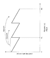
- the low band spectrum is duplicated to the high band two times or more.
- FH 2*FL
- the low band spectrum needs to be duplicated to the high band two times.
- the speech encoding apparatus employs a configuration including: a first encoding section that encodes a low band spectrum comprising a lower band than a threshold frequency of a speech signal; a flattening section that flattens the low band spectrum using an inverse filter with inverse characteristics of a spectral envelope of the speech signal; and a second encoding section that encodes a high band spectrum comprising a higher band than the threshold frequency of the speech signal using the flattened low band spectrum.
- the present invention is able to keep continuity in spectral energy and prevent speech quality deterioration.
- the present invention flattens the spectrum by removing the influence of the spectral envelope from the low band spectrum and encodes the high band spectrum using the flattened spectrum.
- FIG. 5A shows a low band decoded spectrum obtained by conventional encoding/decoding processing.
- FIG.5B shows the spectrum obtained by filtering the decoded spectrum shown in FIG.5A through an inverse filter with inverse characteristics of the spectral envelope. In this way, by filtering the low band decoded spectrum through the inverse filter with the inverse characteristics of the spectral envelope, the low band spectrum is flattened. Then, as shown in FIG.5C , The low band spectrum is duplicated to the high band a plurality of times (here, two times), and the high band is encoded. The low band spectrum is already flattened as shown in FIG.
- a method can be employed for estimating the high band spectrum by using the low band spectrum for the internal state of a pitch filter and carrying out pitch filter processing in order from lower frequency to higher frequency in the frequency domain. According to this encodingmethod, when the high band is encoded, only filter information of the pitch filter needs to be encoded, so that it is possible to realize a lower bit rate.
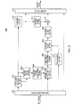
- FIG.6 shows the configuration of a speech encoding apparatus according to Embodiment 1 of the present invention.
- LPC analyzing section 101 carries out LPC analysis of an input speech signal and calculates LPC coefficients ⁇ (i) (1 ⁇ i ⁇ NP).
- NP is the order of the LPC coefficients, and, for example, 10 to 18 is selected.
- the calculated LPC coefficients are inputted to LPC quantizing section 102.
- LPC quantizing section 102 quantizes the LPC coefficients. For efficiency and stability judgment in quantization, after the LPC coefficients are converted to LSP (Line Spectral Pair) parameters, LPC quantizing section 102 quantizes the LSP parameters and outputs LPC coefficient encoded data. The LPC coefficient encoded data is inputted to LPC decoding section 103 and multiplexing section 109.
- LPC decoding section 103 generates decoded LPC coefficients ⁇ q (i)(1 ⁇ i ⁇ NP) by decoding the LPC coefficient encoded data and outputs decoded LPC coefficients ⁇ q (i) (1 ⁇ i ⁇ NP) to inverse filter section 104.
- Inverse filter section 104 forms an inverse filter using the decoded LPC coefficients and flattens the spectrum of the input speech signal by filtering the input speech signal through this inverse filter.
- Equation 2 shows the inverse filter when a resonance suppression coefficient ⁇ (0 ⁇ ⁇ ⁇ 1) for controlling the degree of flattening is used.
- output signal e(n) obtained when speech signal s(n) is inputted to the inverse filter represented by equation 2, is represented by equation 4.
- an output signal of inverse filter section 104 (speech signal where the spectrum is flattened) is referred to as a "prediction residual signal.”
- Frequency domain transforming section 105 carries out a frequency analysis of the prediction residual signal outputted from inverse filter section 104 and finds a residual spectrum as transform coefficients.
- Frequency domain trans forming section 105 transforms a time domain signal into a frequency domain signal using, for example, the MDCT (Modified Discrete Cosine Transform).
- MDCT Modified Discrete Cosine Transform
- the residual spectrum is inputted to first layer encoding section 106 and second layer encoding section 108.
- First layer encoding section 106 encodes the low band of the residual spectrum using, for example, TwinVQ and outputs the first layer encoded data obtained by this encoding, to first layer decoding section 107 and multiplexing section 109.
- First layer decoding section 107 generates a first layer decoded spectrum by decoding the first layer encoded data and outputs the first layer decoded spectrum to second layer encoding section 108. Further, first layer decoding section 107 outputs the first layer decoded spectrum before transform into the time domain.
- Second layer encoding section 108 encodes the high band of the residual spectrum using the first layer decoded spectrum obtained at first layer decoding section 107 and outputs the second layer encoded data obtained by this encoding, to multiplexing section 109.
- Second layer encoding section 108 uses the first layer decoded spectrum for the internal state of the pitch filter and estimates the high band of the residual spectrum by pitch filtering processing. At this time, second layer encoding section 108 estimates the high band of the residual spectrum such that the spectral harmonics structure does not break. Further, second layer encoding section 108 encodes filter information of the pitch filter. Furthermore, second layer encoding section 108 estimates the high band of the residual spectrum using the residual spectrum where the spectrum is flattened.
- second layer encoding section 108 will be described in details later.
- Multiplexing section 109 generates a bit stream by multiplexing the first layer encoded data, the second layer encoded data and the LPC coefficient encoded data, and outputs the bit stream.
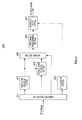
- FIG.7 shows the configuration of second layer encoding section 108.
- Internal state setting section 1081 receives an input of first layer decoded spectrum S1(k) (0 ⁇ k ⁇ FL) from first layer decoding section 107. Internal state setting section 1081 sets the internal state of a filter used at filtering section 1082 using this first layer decoded spectrum.
- Pitch coefficient setting section 1084 outputs pitch coefficient T sequentially to filtering section 1082 according to control by searching section 1083 by changing pitch coefficient T little by little within a predetermined search range of T min to T max .
- Filtering section 1082 filters the first layer decoded spectrum based on the internal state of the filter set in internal state setting section 1081 and pitch coefficient T outputted from pitch coefficient setting section 1084, and calculates estimated value S2' (k) of the residual spectrum. This filtering processing will be described in details later.
- Searching section 1083 calculates a similarity, which is a parameter representing the similarity of residual spectrum S2 (k) (0 ⁇ k ⁇ FH) inputted from frequency domain transforming section 105 and estimated value S2' (k) inputted from filtering section 1082.
- This similarity calculation processing is carried out every time pitch coefficient T is given from pitch coefficient setting section 1084, and pitch coefficient (optimum coefficient) T' (within the range of T min to T max ) that maximizes the calculated similarity, is outputted to multiplexing section 1086. Further, searching section 1083 outputs estimated value S2'(k) of the residual spectrum generated by using this pitch coefficient T', to gain encoding section 1085.
- gain encoding section 1085 calculates subband information B'(j) of estimated value S2' (k) of the residual spectrum according to equation 6, and calculates the amount of fluctuation V(j) on a per subband basis according to equation 7.
- V j B j B ⁇ j
- gain encoding section 1085 finds the amount of fluctuation V g (j) after encoding the amount of fluctuation V(j) and outputs an index to multiplexing section 1086.
- Multiplexing section 1086 multiplexes optimum pitch coefficient T' inputted from searching section 1083 with the index of the amount of fluctuation V(j) inputted from gain encoding section 1085, and outputs the result as the second layer encoded data to multiplexing section 109.
- FIG.8 shows how a spectrum of band FL ⁇ k ⁇ FH is generated using pitch coefficient T inputted from pitch coefficient setting section 1084.
- the spectrum of the entire frequency band (0 ⁇ k ⁇ FH) is referred to as "S (k) " for ease of description and the filter function represented by equation 8 is used.
- T is the pitch coefficient given by pitch coefficient setting section 1084
- first layer decoded spectrum S1(k) is stored as the internal state of the filter.
- estimated value S2'(k) of the residual spectrum determined in the following steps is stored.
- every time pitch coefficient T is given from pitch coefficient setting section 1084, S(k) is subjected to zero clear within the range of FL ⁇ k ⁇ FH. That is, every time pitch coefficient T changes, S(k) is calculated and outputted to searching section 1083.
- the value of pitch coefficient T is smaller than band FL to FH, and so a high band spectrum (FL ⁇ k ⁇ FH) is generated by using a low band spectrum (0 ⁇ k ⁇ FL) recursively.
- the low band spectrum is flattened as described above, and so, even when the high band spectrum is generated by recursively using the low band spectrum by filtering processing, discontinuity in high band spectrum energy does not occur.
- FIG.9 shows the configuration of the speech decoding apparatus according to Embodiment 1 of the present invention.
- This speech decoding apparatus 200 receives a bit stream transmitted from speech encoding apparatus 100 shown in FIG.6 .
- demultiplexing section 201 demultiplexes the bit stream received from speech encoding apparatus 100 shown in FIG. 6 , to the first layer encoded data, the second layer encoded data and the LPC coefficient encoded data, and outputs the first layer encoded data to first layer decoding section 202, the second layer encoded data to second layer decoding section 203 and the LPC coefficient encoded data to LPC decoding section 204. Further, demultiplexing section 201 outputs layer information (i.e. information showing which bit stream includes encoded data of which layer) to deciding section 205.
- layer information i.e. information showing which bit stream includes encoded data of which layer
- First layer decoding section 202 generates the first layer decoded spectrum by carrying out decoding processing using the first layer encoded data, and outputs the first layer decoded spectrum to second layer decoding section 203 and deciding section 205.
- Second layer decoding section 203 generates the second layer decoded spectrum using the second layer encoded data and the first layer decoded spectrum, and outputs the second layer decoded spectrum to deciding section 205. Further, second layer decoding section 203 will be described in details later.
- LPC decoding section 204 outputs the decoded LPC coefficients obtained by decoding LPC coefficient encoded data, to synthesis filter section 207.
- speech encoding apparatus 100 transmits the bit stream including both the first layer encoded data and the second layer encoded data, cases occur where the second layer encoded data is discarded at anywhere in the transmission path. Then, deciding section 205 decides whether or not the second layer encoded data is included in the bit stream based on layer information. Further, when the second layer encoded data is not included in the bit stream, second layer decoding section 203 does not generate the second layer decoded spectrum, and so deciding section 205 outputs the first layer decoded spectrum to time domain transforming section 206.
- deciding section 205 extends the order of the first layer decoded spectrum to FH and outputs the spectrum of FL to FH as "zero.”
- deciding section 205 outputs the second layer decoded spectrum to time domain transforming section 206.
- Time domain transforming section 206 generates a decoded residual signal by transforming the decoded spectrum inputted from deciding section 205, to a time domain signal and outputs the signal to synthesis filter section 207.
- Synthesis filter section 207 forms a synthesis filter using the decoded LPC coefficients ⁇ q (i) (1 ⁇ i ⁇ NP) inputted from LPC decoding section 204.
- FIG.10 shows the configuration of second layer decoding section 203.
- Internal state setting section 2031 receives an input of the first layer decoded spectrum from first layer decoding section 202. Internal state setting section 2031 sets the internal state of the filterusedat filtering section 2033 by using first layer decoded spectrum S1 (k).
- demultiplexing section 2032 receives an input of the second layer encoded data from multiplexing section 201.
- Demultiplexing section 2032 demultiplexes the second layer encoded data to information related to the filtering coefficient (optimum pitch coefficient T') and information related to the gain (the index of the amount of fluctuation V(j)), and outputs information related to the filtering coefficient to filtering section 2033 and information related to the gain to gain decoding section 2034.
- Filtering section 2033 filters first layer decoded spectrum S1(k) based on the internal state of the filter set at internal state setting section 2031 and pitch coefficient T' inputted from demultiplexing section 2032, and calculates estimated value S2' (k) of the residual spectrum.
- the filter function shown in equation 8 is used in filtering section 2033.
- Gain decoding section 2034 decodes gain information inputted from demultiplexing section 2032 and finds the amount of fluctuation V q (j) obtained by encoding the amount of fluctuation V(j).
- Spectrum adjusting section 2035 adjusts the spectral shape of frequency band FL ⁇ k ⁇ FH of decoded spectrum S'(k) by multiplying according to equation 14 decoded spectrum S'(k) inputted from filtering section 2033 by the decoded amount of fluctuation V q (j) of each subband inputted from gain decoding section 2034, and generates decoded spectrum S3 (k) after the adjustment.
- This decoded spectrum S3(k) after the adjustment is outputted to deciding section 205 as the second layer decoded spectrum.
- S ⁇ 3 k S ⁇ k ⁇ V q j BL j ⁇ k ⁇ BH j , forall j
- speech decoding apparatus 200 is able to decode a bit stream transmitted from speech encoding apparatus 100 shown in FIG.6 .
- time domain encoding for example, CELP encoding
- the spectrum of the first layer decoded signal is flattened using the decoded LPC coefficients determined during encoding processing in the first layer.
- FIG.11 shows the configuration of the speech encoding apparatus according to Embodiment 2 of the present invention.
- the same components as in Embodiment 1 FIG.6
- the same reference numerals and repetition of description will be omitted.
- down-sampling section 301 down-samples a sampling rate for an input speech signal and outputs a speech signal of a desired sampling rate to first layer encoding section 302.
- First layer encoding section 302 generates the first layer encoded data by encoding the speech signal down-sampled to the desired sampling rate and outputs the first layer encoded data to first layer decoding section 303 and multiplexing section 109.
- First layer encoding section 302 uses, for example, CELP encoding.
- first layer encoding section 302 is able to generate decoded LPC coefficients during this encoding processing. Then, first layer encoding section 302 outputs the first layer decoded LPC coefficients generated during the encoding processing, to inverse filter section 304.
- First layer decoding section 303 generates the first layer decoded signal by carrying out decoding processing using the first layer encoded data, and outputs this signal to inverse filter section 304.
- Inverse filter section 304 forms an inverse filter using the first layer decoded LPC coefficients inputted from first layer encoding section 302 and flattens the spectrum of the first layer decoded signal by filtering the first layer decoded signal through this inverse filter. Further, details of the inverse filter are the same as in Embodiment 1 and so repetition of description is omitted. Furthermore, in the following description, an output signal of inverse filter section 304 (i.e. the first layer decoded signal where the spectrum is flattened) is referred to as a "first layer decoded residual signal.”
- Frequency domain transforming section 305 generates the first layer decoded spectrum by carrying out a frequency analysis of the first layer decoded residual signal outputted from inverse filter section 304, and outputs the first layer decoded spectrum to second layer encoding section 108.
- delaying section 306 adds the predetermined period of delay to the input speech signal.
- the amount of this delay takes the same value as the delay time that occurs when the input speech signal passes through down-sampling section 301, first layer encoding section 302, first layer decoding section 303, inverse filter section 304, and frequency domain transforming section 305.
- the spectrum of the first layer decoded signal is flattened using the decoded LPC coefficients (first layer decoded LPC coefficients) determined during the encoding processing in the first layer, so that it is possible to flatten the spectrum of the first layer decoded signal using information of first layer encoded data. Consequently, according to this embodiment, the LPC coefficients for flattening the spectrum of the first layer decoded signal do not require encoded bits, so that it is possible to flatten the spectrum without increasing the amount of information.
- FIG.12 shows the configuration of the speech decoding apparatus according to Embodiment 2 of the present invention.
- This speech decoding apparatus 400 receives a bit stream transmitted from speech encoding apparatus 300 shown in FIG.11 .
- demultiplexing section 401 demultiplexes the bit stream received from speech encoding apparatus 300 shown in FIG.11 , to the first layer encoded data, the second layer encoded data and the LPC coefficient encoded data, and outputs the first layer encoded data to first layer decoding section 402, the second layer encoded data to second layer decoding section 405 and the LPC coefficient encoded data to LPC decoding section 407. Further, demultiplexing section 401 outputs layer information (i.e. information showing which bit stream includes encoded data of which layer) to deciding section 413.
- layer information i.e. information showing which bit stream includes encoded data of which layer
- First layer decoding section 402 generates the first layer decoded signal by carrying out decoding processing using the first layer encoded data and outputs the first layer decoded signal to inverse filter section 403 and up-sampling section 410. Further, first layer decoding section 402 outputs the first layer decoded LPC coefficients generated during the decoding processing, to inverse filter section 403.
- Up-sampling section 410 up-samples the sampling rate for the first layer decoded signal to the same sampling rate for the input speech signal of FIG.11 , and outputs the first layer decoded signal to low-pass filter section 411 and deciding section 413.
- Low-pass filter section 411 sets a pass band of 0 to FL in advance, generates a low band signal by passing the up-sampled first layer decoded signal of frequency band 0 to FL and outputs the low band signal to adding section 412.
- Inverse filter section 403 forms an inverse filter using the first layer decoded LPC coefficients inputted from first layer decoding section 402, generates the first layer decoded residual signal by filtering the first layer decoded signal through this inverse filter and outputs the first layer decoded residual signal to frequency domain transforming section 404.
- Frequency domain transforming section 404 generates the first layer decoded spectrum by carrying out a frequency analysis of the first layer decoded residual signal outputted from inverse filter section 403 and outputs the first layer decoded spectrum to second layer decoding section 405.
- Second layer decoding section 405 generates the second layer decoded spectrum using the second layer encoded data and the first layer decoded spectrum and outputs the second layer decoded spectrum to time domain transforming section 406. Further, details of second layer decoding section 405 are the same as second layer decoding section 203 ( FIG.9 ) of Embodiment 1 and so repetition of description is omitted.
- Time domain transforming section 406 generates the second layer decoded residual signal by transforming the second layer decoded spectrum to a time domain signal and outputs the second layer decoded residual signal to synthesis filter section 408.
- LPC decoding section 407 outputs the decoded LPC coefficients obtained by decoding the LPC coefficient encoded data, to synthesis filter section 408.
- Synthesis filter section 408 forms a synthesis filter using the decoded LPC coefficients inputted from LPC decoding section 407. Further, details of synthesis filter 408 are the same as synthesis filter section 207 ( FIG.9 ) of Embodiment 1 and so repetition of description is omitted. Synthesis filter section 408 generates second layer synthesized signal s q (n) as in Embodiment 1 and outputs this signal to high-pass filter section 409.
- High-pass filter section 409 sets the pass band of FL to FH in advance, generates a high band signal by passing the second layer synthesized signal of frequency band FL to FH and outputs the high band signal to adding section 412.
- Adding section 412 generates the second layer decoded signal by adding the low band signal and the high band signal and outputs the second layer decoded signal to deciding section 413.
- Deciding section 413 decides whether or not the second layer encoded data is included in the bit stream based on layer information inputted from demultiplexing section 401, selects either the first layer decoded signal or the second layer decoded signal, and outputs this signal as a decoded signal. If the second layer encoded data is not included in the bit stream, Deciding section 413 outputs the first layer decoded signal, and, if both the first layer encoded data and the second layer encoded data are included in the bit stream, outputs the second layer decoded signal.
- low-pass filter section 411 and high-pass filter section 409 are used to ease the influence of the low band signal and the high band signal upon each other. Consequently, when the influence of the low band signal and the high band signal upon each other is less, a configuration not using these filters may be possible. When these filters are not used, operation according to filtering is not necessary, so that it is possible to reduce the amount of operation.
- speech decoding apparatus 400 is able to decode a bit stream transmitted from speech encoding apparatus 300 shown in FIG.11 .
- the spectrum of the first layer excitation signal is flattened in the same way as the spectrum of the prediction residual signal where the influence of the spectral envelope is removed from the input speech signal. Then, with this embodiment, the first layer excitation signal determined during encoding processing in the first layer is processed as a signal where the spectrum is flattened (that is, the first layer decoded residual signal of Embodiment 2).
- FIG.13 shows the configuration of the speech encoding apparatus according to Embodiment 3 of the present invention.
- the same components as in Embodiment 2 FIG.11 ) will be assigned the same reference numerals and repetition of description will be omitted.
- First layer encoding section 501 generates the first layer encoded data by encoding a speech signal down-sampled to a desired sampling rate, and outputs the first layer encoded data to multiplexing section 109.
- First layer encoding section 501 uses, for example, CELP encoding.
- first layer encoding section 501 outputs the first layer excitation signal generated during the encoding processing, to frequency domain transforming section 502.
- an excitation signal is a signal inputted to a synthesis filter (or perceptual weighting synthesis filter) inside first layer encoding section 501 that carries out CELP encoding, and is also referred to as a "excitation signal.”
- Frequency domain transforming section 502 generates the first layer decoded spectrum by carrying out a frequency analysis of the first layer excitation signal, and outputs the first layer decoded signal to second layer encoding section 108.
- the amount of delay of delaying section 503 takes the same value as the delay time that occurs when the input speech signal passes through down-sampling section 301, first layer encoding section 501, and frequency domain transforming section 502.
- first layer decoding section 303 and inverse filter section 304 are not necessary, compared to Embodiment 2 ( FIG.11 ), so that it is possible to reduce the amount of operation.
- FIG.14 shows the configuration of the speech decoding apparatus according to Embodiment 3 of the present invention.
- This speech decoding apparatus 600 receives a bit stream transmitted from speech encoding apparatus 500 shown in FIG.13 .
- the same components as in Embodiment 2 FIG.12
- will be assigned the same reference numerals and repetition of description will be omitted.
- First layer decoding section 601 generates the first layer decoded signal by carrying out decoding processing using the first layer encoded data, and outputs the first layer decoded signal to up-sampling section 410. Further, first layer decoding section 601 outputs the first layer excitation signal generated during decoding processing to frequency domain transforming section 602.
- Frequency domain transforming section 602 generates the first layer decoded spectrum by carrying out a frequency analysis of the first layer excitation signal and outputs the first layer decoded spectrum to second layer decoding section 405.
- speech decoding apparatus 600 is able to decode a bit stream transmitted from speech encoding apparatus 500 shown in FIG.13 .
- the spectra of the first layer decoded signal and an input speech signal are flattened using the second layer decoded LPC coefficients determined in the second layer.
- FIG.15 shows the configuration of the speech encoding apparatus 700 according to Embodiment 4 of the present invention.
- the same components as in Embodiment 2 FIG.11 ) will be assigned the same reference numerals and repetition of description will be omitted.
- First layer encoding section 701 generates the first layer encoded data by encoding the speech signal down-sampled to the desired sampling rate and outputs the first layer encoded data to first layer decoding section 702 and multiplexing section 109.
- First layer encoding section 701 uses, for example, CELP encoding.
- First layer decoding section 702 generates the first layer decoded signal by carrying out decoding processing using the first layer encoded data and outputs this signal to up-sampling section 703.
- Up-sampling section 703 up-samples a sampling rate for the first layer decoded signal to the same sampling rate for the input speech signal, and outputs the first layer decoded signal to inverse filter section 704.
- inverse filter section 704 receives the decoded LPC coefficients from LPC decoding section 103. Inverse filter section 704 forms an inverse filter using the decoded LPC coefficients and flattens the spectrum of the first layer decoded signal by filtering the up-sampled first layer decoded signal through this inverse filter. Further, in the following description, an output signal of inverse filter section 704 (first layer decoded signal where the spectrum is flattened) is referred to as the "first layer decoded residual signal.”
- Frequency domain transforming section 705 generates the first layer decoded spectrum by carrying out a frequency analysis of the first layer decoded residual signal outputted from inverse filter section 704 and outputs the first layer decoded spectrum to second layer encoding section 108.
- the amount of delay of delaying section 706 takes the same value as the delay time that occurs when the input speech signal passes through down-sampling section 301, first layer encoding section 701, first layer decoding section 702, up-sampling section 703, inverse filter section 704, and frequency domain transforming section 705.
- FIG.16 shows the configuration of the speech decoding apparatus according to Embodiment 4 of the present invention.
- This speech decoding apparatus 800 receives a bit stream transmitted from speech encoding apparatus 700 shown in FIG.15 .
- the same components as in Embodiment 2 FIG.12
- will be assigned the same reference numerals and repetition of description will be omitted.
- First layer decoding section 801 generates the first layer decoded signal by carrying out decoding processing using the first layer encoded data and outputs this signal to up-sampling section 802.
- Up-sampling section 802 up-samples the sampling rate for the first layer decoded signal to the same sampling rate for the input speech signal of FIG.15 , and outputs the first layer decoded signal to inverse filter section 803 and deciding section 413.
- inverse filter section 803 receives the decoded LPC coefficients from LPC decoding section 407.
- Inverse filter section 803 forms an inverse filter using the decoded LPC coefficients, flattens the spectrum of the first layer decoded signal by filtering the up-sampled first layer decoded signal through this inverse filter, and outputs the first layer decoded residual signal to frequency domain transforming section 804.
- Frequency domain transforming section 804 generates the first layer decoded spectrum by carrying out a frequency analysis of the first layer decoded residual signal outputted from inverse filter section 803 and outputs the first layer decoded spectrum to second layer decoding section 405.
- speech decoding apparatus 800 is able to decode a bit stream transmitted from speech encoding apparatus 700 shown in FIG.15 .
- the speech encoding apparatus flattens the spectra of the first layer decoded signal and an input speech signal using the second layer decoded LPC coefficients determined in the second layer, so that it is possible to find the first layer decoded spectrum using LPC coefficients that are common between the speech decoding apparatus and the speech encoding apparatus. Therefore, according to this embodiment, when the speech decoding apparatus generates a decoded signal, separate processing for the low band and the high band as described in Embodiments 2 and 3 is no longer necessary, so that a low-pass filter and a high-pass filter are not necessary, a configuration of an apparatus becomes simple and it is possible to reduce the amount of operation of filtering processing.
- the degree of flattening is controlled by adaptively changing a resonance suppression coefficient of an inverse filter for flattening a spectrum, according to characteristics of an input speech signal.
- FIG.17 shows the configuration of speech encoding apparatus 900 according to Embodiment 5 of the present invention.
- the same components as in Embodiment 4 FIG.15 ) will be assigned the same reference numerals and repetition of description will be omitted.
- inverse filter sections 904 and 905 are represented by equation 2.
- Feature amount analyzing section 901 calculates the amount of feature by analyzing the input speech signal, and outputs the amount of feature to feature amount encoding section 902.
- the amount of feature a parameter representing the intensity of a speech spectrum with respect to resonance is used.
- the distance between adjacent LSP parameters is used.
- the degree of resonance is stronger and the energy of the spectrum corresponding to the resonance frequency is greater.
- the degree of flattening is set little by setting above resonance suppression coefficient ⁇ (0 ⁇ ⁇ ⁇ 1) little in a speech period where resonance is stronger.
- Feature amount encoding section 902 generates feature amount encoded data by encoding the amount of feature inputted from feature amount analyzing section 901 and outputs the feature amount encoded data to feature amount decoding section 903 and multiplexing section 906.
- Feature amount decoding section 903 decodes the amount of feature using feature amount encoded data, determines resonance suppression coefficient ⁇ used at inverse filter sections 904 and 905 according to the decoding amount of feature and outputs resonance suppression coefficient ⁇ to inverse filter sections 904 and 905.
- resonance suppression coefficient ⁇ is set greater if the periodicity of an input speech signal is greater, and resonance suppression coefficient ⁇ is set smaller if the periodicity of the input signal is less.
- Inverse filter sections 904 and 905 carry out inverse filter processing based on resonance suppression coefficient ⁇ controlled at feature amount decoding section 903 according to equation 2.
- Multiplexing section 906 generates a bit stream by multiplexing the first layer encoded data, the second layer encoded data, the LPC coefficient encoded data and the feature amount encoded data, and outputs the bit stream.
- the amount of delay of delaying section 907 takes the same value as the delay time that occurs when the input speech signal passes through down-sampling section 301, first layer encoding section 701, first layer decoding section 702, up-sampling section 703, inverse filter section 905 and frequency domain transforming section 705.
- FIG.18 shows the configuration of the speech decoding apparatus according to Embodiment 5 of the present invention.
- This speech decoding apparatus 1000 receives a bit stream transmitted from speech encoding apparatus 900 shown in FIG.17 .
- the same components as in Embodiment 4 FIG.16 ) will be assigned the same reference numerals and repetition of description will be omitted.
- inverse filter section 1003 is represented by equation 2.
- Demultiplexing section 1001 demultiplexes the bit stream received from speech encoding apparatus 900 shown in FIG.17 , to the first layer encoded data, the second layer encoded data, the LPC coefficient encoded data and the feature amount encoded data, and outputs the first layer encoded data to first layer decoding section 801, the second layer encoded data to second layer decoding section 405, the LPC coefficient encoded data to LPC decoding section 407 and the feature amount encoded data to feature amount decoding section 1002. Further, demultiplexing section 1001 outputs layer information (i.e. information showing which bit stream includes encoded data of which layer) is outputted to deciding section 413.
- layer information i.e. information showing which bit stream includes encoded data of which layer
- feature amount decoding section 1002 decodes the amount of feature using the feature amount encoded data, determines resonance suppression coefficienty used at inverse filter section 1003 according to the decoding amount of feature and outputs resonance suppression coefficient ⁇ to inverse filter section 1003.
- Inverse filter section 1003 carries out inverse filtering processing based on resonance suppression coefficient ⁇ controlled at feature amount decoding section 1002 according to equation 2.
- speech decoding apparatus 1000 is able to decode a bit stream transmitted from speech encoding apparatus 900 shown in FIG.17 .
- LPC quantizing section 102 converts the LPC coefficients to LSP parameters first and quantizes the LSP parameters. Then, in this embodiment, a configuration of the speech encoding apparatus may be as shown in FIG.19 . That is, in speech encoding apparatus 1100 shown in FIG. 19 , feature amount analyzing section 901 is not provided, and LPC quantizing section 102 calculates the distance between LSP parameters and outputs the distance to feature amount encoding section 902.
- LPC quantizing section 102 when LPC quantizing section 102 generates decoded LSP parameters, the configuration of the speech encoding apparatus may be as shown in FIG.20 . That is, in speech encoding apparatus 1300 shown in FIG. 20 , feature amount analyzing section 901, feature amount encoding section 902 and feature amount decoding section 903 are not provided, and LPC quantizing section 102 generates the decoded LSP parameters, calculates the distance between the decoded LSP parameters and outputs the distance to inverse filter section 904 and 905.
- FIG.21 shows the configuration of speech decoding apparatus 1400 that decodes a bit stream transmitted from speech encoding apparatus 1300 shown in FIG.20 .
- LPC decoding section 407 further calculates the distance between the decoded LSP parameters and outputs the distance to inverse filter section 1003.
- this modification information is encoded in the speech encoding apparatus, if the number of encoding candidates is not sufficient, that is, if the bit rate is low, a large quantization error occurs. Then, if such a large quantization error occurs, the dynamic range of the low band spectrum is not sufficiently adjusted due to the quantization error, and, as a result, quality deterioration occurs. Particularly, when an encoding candidate showing a dynamic range larger than the dynamic range of the high band spectrum is selected, an undesirable peak in the high band spectrum is likely to occur and cases occur where quality deterioration shows remarkably.
- FIG.22 shows the configuration of second layer encoding section 108 according to Embodiment 6 of the present invention.
- the same components as in Embodiment 1 FIG.7 ) will be assigned the same reference numerals and repetition of description will be omitted.
- spectrum modifying section 1087 receives an input of first layer decoded spectrum S1(k)(0 ⁇ k ⁇ FL) from first layer decoding section 107 and an input of residual spectrum S2(k) (0 ⁇ k ⁇ FH) from frequency domain transforming section 105.
- Spectrum modifying section 1087 changes the dynamic range of decoded spectrum S1(k) by modifying decoded spectrum S1 (k) such that the dynamic range of decoded spectrum S1 (k) is adjusted to an adequate dynamic range.
- spectrum modifying section 1087 encodes modification information showing how decoded spectrum S1(k) is modified, and outputs encoded modification information to multiplexing section 1086. Further, spectrum modifying section 1087 outputs modified decoded spectrum (modified decoded spectrum) S1'(j, k) to internal state setting section 1081.
- FIG.23 shows the configuration of spectrum modifying section 1087.
- Spectrum modifying section 1087 modifies decoded spectrum S1(k) and adjusts the dynamic range of decoded spectrum S1(k) closer to the dynamic range of the high band (FL ⁇ k ⁇ FH) of residual spectrum S2(k). Further, spectrum modifying section 1087 encodes modification information and outputs encoded modification information.
- modified spectrum generating section 1101 generates modified decoded spectrum S1' (j, k) by modifying decoded spectrum S1(k) and outputs modified decoded spectrum S1'(j, k) to subband energy calculating section 1102.
- j is an index for identifying each encoding candidate (each modification information) of codebook 1111
- modified spectrum generating section 1101 modifies decoded spectrum S1(k) using each encoding candidate (each modification information) included in codebook 1111.
- a case will be described as an example where a spectrum is modified using an exponential function.
- each encoding candidate ⁇ (j) is within the range of 0 ⁇ ⁇ (j) ⁇ 1.
- sign() is the function for returning a positive or negative sign. Consequently, when encoding candidate ⁇ (j) takes a value closer to "zero," the dynamic range of the modified decoded spectrum S1' (j, k) becomes smaller.
- Subband energy calculating section 1102 divides the frequency band of modified decoded spectrum S1'(j, k) into a plurality of subbands, calculates average energy (subband energy) P1(j, n) of each subband, and outputs average energy P1(j, n) to variance calculating section 1103.
- n is a subband number.
- Variance calculating section 1103 calculates variance ⁇ 1(j) 2 of subband energy P1 (j, n) to show the degree of dispersion of subband energy P1 (j, n). Then, variance calculating section 1103 outputs variance ⁇ 1(j) 2 of encoding candidate (modification information) j to subtracting section 1106.
- subband energy calculating section 1104 divides the high band of residual spectrum S2(k) into a plurality of subbands, calculates average energy (subband energy) P2 (n) of each subband and outputs average energy P2 to variance calculating section 1105.
- variance calculating section 1105 calculates variance ⁇ 2 2 of subband energy P2(n), and outputs variance ⁇ 2 2 of subband energy P2 (n) to subtracting section 1106.
- Subtracting section 1106 subtracts variance ⁇ 1(j) 2 from variance ⁇ 2 2 and outputs an error signal obtained by this subtraction to deciding section 1107 and weighted error calculating section 1108.
- Deciding section 1107 decides a sign (positive or negative) of the error signal and determines the weight given to weighted error calculating section 1108 based on the decision result. If the sign of the error signal is positive, deciding section 1107 selects w pos , and if the sign of the error signal is negative, selects w neg as the weight, and outputs the weight to weighted error calculating section 1108.
- the relationship shown in equation 16 holds between w pos and w neg . [16] 0 ⁇ w pos ⁇ w neg
- weighted error calculating section 1108 calculates the square value of the error signal inputted from subtracting section 1106, then calculates weighted square error E by multiplying the square value of the error signal by weight W (w pos or w neg ) inputted from deciding section 1107 and outputs weighted square error E to searching section 1109.
- Searching section 1109 controls codebook 1111 to output encoding candidates (modification information) stored in codebook 1111 sequentially to modified spectrum generating section 1101 and search for the encoding candidate (modification information) that minimizes weighted square error E. Then, searching section 1109 outputs index j opt of the encoding candidate that minimizes weighted square error E as optimum modification information to modified spectrum generating section 1110 and multiplexing section 1086.
- Modified spectrum generating section 1110 generates modified decoded spectrum S1'(j opt , k) corresponding to optimum modification information j opt by modifying decoded spectrum S1 (k) and outputs modified decoded spectrum S1' (j opt , k) to internal state setting section 1081.
- FIG.24 shows the configuration of second layer decoding section 203 according to Embodiment 6 of the present invention.
- the same components as in Embodiment 1 FIG.10
- the same reference numerals and repetition of description will be omitted.
- modified spectrum generating section 2036 generates modified decoded spectrum S1'(j opt , k) by modifying first layer decoded spectrum S1 (k) inputted from first layer decoding section 202 based on optimum modification information j opt inputted from demultiplexing section 2032, and outputs modified decoded spectrum S1' (j opt , k) to internal state setting section 2031. That is, modified spectrum generating section 2036 is provided in relationship to modified spectrum generating section 1110 on the speech encoding apparatus side and carries out the same processing as in modified spectrum generating section 1110.
- a case where the error signal is positive refers to a case where the degree of dispersion of modified decoded spectrum S1' becomes less than the degree of dispersion of residual spectrum S2 as the target value. That is, this corresponds to a case where the dynamic range of modified decoded spectrum S1' generated on the speech decoding apparatus side becomes smaller than the dynamic range of residual spectrum S2.
- a case where the error signal is negative refers to a case where the degree of dispersion of modified decoded spectrum S1' is greater than the degree of dispersion of residual spectrum S2 which is the target value. That is, this corresponds to a case where the dynamic range of modified decoded spectrum S1' generated on the speech decoding apparatus side becomes larger than the dynamic range of residual spectrum S2.
- the present invention is not limited to the variance of average subband energy as long as indices showing the amount of the dynamic range of a spectrum are used.
- FIG.25 shows the configuration of spectrum modifying section 1087 according to Embodiment 7 of the present invention.
- the same components as in Embodiment 6 ( FIG.23 ) will be assigned the same reference numerals and repetition of description will be omitted.
- dispersion degree calculating section 1112-1 calculates the degree of dispersion of decoded spectrum S1(k) from the distribution of values in the low band of decoded spectrum S1 (k), and outputs the degree of dispersion to threshold setting sections 1113-1 and 1113-2.
- the degree of dispersion is standard deviation ⁇ 1 of decoded spectrum S1(k).
- Threshold setting section 1113-1 finds first threshold TH1 using standard deviation ⁇ 1 and outputs threshold TH1 to average spectrum calculating section 1114-1 and modified spectrum generating section 1110.
- first threshold TH1 refers to a threshold for specifying the spectral values with comparatively high amplitude among decoded spectrum S1(k), and uses the value obtained by multiplying standard deviation ⁇ 1 by predetermined constant a.
- Threshold setting section 1113-2 finds second threshold TH2 using standard deviation ⁇ 1 and outputs second threshold TH2 to average spectrum calculating section 1114-2 and modified spectrum generating section 1110.
- second threshold TH2 is a threshold for specifying the spectral values with comparatively low amplitude among the low band of decoded spectrum S1(k), and uses the value obtained by multiplying standard deviation ⁇ 1 by predetermined constant b( ⁇ a).
- Average spectrum calculating section 1114-1 calculates an average amplitude value of a spectrum with higher amplitude than first threshold TH1 (hereinafter “first average value”) and outputs the average amplitude value to modified vector calculating section 1115.
- first average value an average amplitude value of a spectrum with higher amplitude than first threshold TH1
- average spectrum calculating section 1114-1 compares the spectral value of the low band of decoded spectrum S1(k) with the value (m1+TH1) obtained by adding first threshold TH1 to average value m1 of decoded spectrum S1(k), and specifies the spectral values with higher values than this value (step 1).
- average spectrum calculating section 1114-1 compares the spectral value of the low band of decoded spectrum S1(k) with the value (m1 - TH1) obtained by subtracting first threshold TH1 from average value m1 of decoded spectrum S1(k), and specifies the spectral values with lower values than this value (step 2). Then, average spectrum calculating section 1114-1 calculates an average amplitude value of the spectral values determined in step 1 and step 2 and outputs the average amplitude value of the spectral values to modified vector calculating section 1115.
- Average spectrum calculating section 1114-2 calculates an average amplitude value (hereinafter "second average value”) of the spectral values with lower amplitude than second threshold TH2, and outputs the average amplitude value to modified vector calculating section 1115.
- second average value an average amplitude value of the spectral values with lower amplitude than second threshold TH2
- average spectrum calculating section 1114-2 compares the spectral value of the low band of decoded spectrum S1 (k) with the value (m1 + TH2) obtained by adding second threshold TH2 to average value m1 of decoded spectrum S1(k), and specifies the spectral values with lower values than this value (step 1).
- average spectrum calculating section 1114-2 compares the spectral value of the low band of decoded spectrum S1(k) with the value (m1-TH2) obtained by subtracting second threshold TH2 from average value m1 of decoded spectrum S1(k), and specifies the spectral values with higher values than this value (step 2). Then, average spectrum calculating section 1114-2 calculates an average amplitude value of the spectral values determined in step 1 and step 2 and outputs the average amplitude value of the spectrum to modified vector calculating section 1115.
- dispersion degree calculating section 1112-2 calculates the degree of dispersion of residual spectrum S2 (k) from the distribution of values in the high band of residual spectrum S2 (k) and outputs the degree of dispersion to threshold setting sections 1113-3 and 1113-4.
- the degree of dispersion is standard deviation ⁇ 2 of residual spectrum S2(k).
- Threshold setting section 1113-3 finds third threshold TH3 using standard deviation ⁇ 2 and outputs third threshold TH3 to average spectrum calculating section 1114-3.
- third threshold TH3 is a threshold for specifying the spectral values with comparatively high amplitude among the high band of residual spectrum S2(k), and uses the value obtained by multiplying standard deviation ⁇ 2 by predetermined constant c.
- Threshold setting section 1113-4 finds fourth threshold TH4 using standard deviation ⁇ 2 and outputs fourth threshold TH4 to average spectrum calculating section 1114-4.
- fourth threshold TH4 is a threshold for specifying the spectral values with comparatively low amplitude among the high band of residual spectrum S2(k), and the value obtained by multiplying standard deviation ⁇ 2 by predetermined constant d( ⁇ c) is used.
- Average spectrum calculating section 1114-3 calculates an average amplitude value (hereinafter "third average value”) of the spectral values with higher amplitude than third threshold TH3 and outputs the average amplitude value to modified vector calculating section 1115.
- average spectrum calculating section 1114-3 compares the spectral value of the high band of residual spectrum S2 (k) with the value (m3 + TH3) obtained by adding third threshold TH3 to average value m3 of residual spectrum S2(k), and specifies the spectral values with higher values than this value (step 1).
- average spectrum calculating section 1114-3 compares the spectral value of the high band of residual spectrum S2 (k) with the value (m3 - TH3) obtained by subtracting third threshold TH3 from average value m3 of residual spectrum S2(k), and specifies the spectral values with lower values than this value (step 2). Then, average spectrum calculating section 1114-3 calculates an average amplitude value of the spectral values determined in step 1 and step 2, and outputs the average amplitude value of the spectrum to modified vector calculating section 1115.
- Average spectrum calculating section 1114-4 calculates an average amplitude value (hereinafter "fourth average value”) of the spectral values with lower amplitude than fourth threshold TH4, and outputs the average amplitude value to modified vector calculating section 1115.
- average spectrum calculating section 1114-4 compares the spectral value of the high band of residual spectrum S2 (k) with the value (m3 + TH4) obtained by adding fourth threshold TH4 to average value m3 of residual spectrum S2(k), and specifies the spectral values with lower values than this value (step 1).
- average spectrum calculating section 1114-4 compares the spectral value of the high band of residual spectrum S2 (k) with the value (m3 - TH4) obtained by subtracting fourth threshold TH4 from average value m3 of residual spectrum S2 (k), and specifies the spectral values with higher values than this value (step 2). Then, average spectrum calculating section 1114-4 calculates an average amplitude value of the spectrum determined in step 1 and step 2, and outputs the average amplitude value of the spectrum to modified vector calculating section 1115.
- Modified vector calculating section 1115 calculates a modified vector as described below using the first average value, the second average value, the third average value and the fourth average value.
- modified vector calculating section 1115 calculates the ratio of the third average value to the first average value (hereinafter the "first gain”) and the ratio of the fourth average value to the second average value (hereinafter the "second gain”), and outputs the first gain and the second gain to subtracting section 1106 as modified vectors.
- Subtracting section 1106 subtracts encoding candidates that belong to modified vector codebook 1116, from modified vector g(i), and outputs the error signal obtained from this subtraction to deciding section 1107 and weighted error calculating section 1108.
- encoding candidates are represented as v(j, i).
- j is an index for identifying each encoding candidate (each modification information) of modified vector codebook 1116.
- Deciding section 1107 decides the sign of an error signal (positive or negative), and determines a weight given to weighted error calculating section 1108 for first gain g (1) and second gain g(2), respectively based on the decision result. With respect to first gain g (1), if the sign of the error signal is positive, deciding section 1107 selects w light as the weight, and, if the sign of the error signal is negative, selects w heavy as the weight, and outputs the result to weighted error calculating section 1108.
- weighted error calculating section 1108 calculates the square value of the error signal inputted from subtracting section 1106, then calculates weighted square error E by calculating the sum of product of the square value of the error signal and each weight w(w light or w heavy ) inputted from deciding section 1107 for first gain g (1) and second gain g (2) and outputs weighted square error E to searching section 1109.
- Searching section 1109 controls modified vector codebook 1116 to output encoding candidates (modification information) stored in modified vector codebook 1116 sequentially to subtracting section 1106, and searches for the encoding candidate (modification information) that minimizes weighted square error E. Then, searching section 1109 outputs index j opt of the encoding candidate that minimizes weighted square error E to modified spectrum generating section 1110 and multiplexing section 1086 as optimum modification information.
- Modified spectrum generating section 1110 generates modified decoded spectrum S1'(j opt , k) corresponding to optimum modification information j opt by modifying decoded spectrum S1 (k) using first threshold TH1, second threshold TH2 and optimum modification information j opt and outputs modified decoded spectrum S1'(j opt , k) to internal state setting section 1081.
- Modified spectrum generating section 1110 first, generates a decoded value (hereinafter the "decoded first gain”) of the ratio of the third average value to the first average value and a decoded value (hereinafter the “decoded second gain”) of the ratio of the fourth average value to the second average value using optimum modification information j opt .
- decoded first gain a decoded value of the ratio of the third average value to the first average value
- decoded second gain a decoded value of the ratio of the fourth average value to the second average value using optimum modification information j opt .
- modified spectrum generating section 1110 compares the amplitude value of decoded spectrum S1(k) with first threshold TH1, specifies the spectral values with higher amplitude than first threshold TH1 and generates modified decoded spectrum S1'(j opt , k) by multiplying these spectral values by the decoded first gain. Similarly, modified spectrum generating section 1110 compares the amplitude value of decoded spectrum S1(k) with second threshold TH2, specifies spectral values with lower amplitude than second threshold TH2 and generates modified decoded spectrum S1'(j opt , k) by multiplying these spectral values by the decoded second gain.
- modified spectrum generating section 1110 uses a gain of an intermediate value between the decoded first gain and the decoded second gain. For example, modified spectrum generating section 1110 finds decoded gain y corresponding to given amplitude x from a characteristic curve based on the decoded first gain, the decoded second gain, first threshold TH1 and second threshold TH2, and multiplies amplitude of decoded spectrum S1(k) by this decoded gain y. That is, decoded gain y is a linear interpolation value of the decoded first gain and the decoded second gain.
- FIG.26 shows the configuration of spectrum modifying section 1087 according to Embodiment 8 of the present invention.
- the same components as in Embodiment 6 FIG.23 ) will be assigned the same reference numerals and repetition of description will be omitted.
- correcting section 1117 receives an input of variance ⁇ 2 2 from variance calculating section 1105.
- Correcting section 1117 carries out correction processing such that the value of variance ⁇ 2 2 becomes smaller and outputs the result to subtracting section 1106. To be more specific, correcting section 1117 multiplies variance ⁇ 2 2 by a value equal to or more than 0 and less than 1.
- Subtracting section 1106 subtracts variance ⁇ 1(j) 2 from the variance after the correction processing, and outputs the error signal obtained by this subtraction to error calculating section 1118.
- Error calculating section 1118 calculates the square value (square error) of the error signal inputted from subtracting section 1106 and outputs the square value to searching section 1109.
- Searching section 1109 controls codebook 1111 to output encoding candidates (modification information) stored in codebook 1111 sequentially to modified spectrum generating section 1101, and searches for the encoding candidate (modification information) that minimizes the square error. Then, searching section 1109 outputs index j opt of the encoding candidate that minimizes the square error to modified spectrum generating section 1110 and multiplexing section 1086 as optimum modification information.
- encoding candidate search is carried out such that the variance after the correction processing, that is, the variance with a value set smaller, is a target value. Consequently, the speech decoding apparatus is able to suppress the dynamic range of an estimated spectrum, so that it is possible to further reduce the frequency of occurrences of an undesirable peak as described above.
- correcting section 1117 may change the value to be multiplied by variance ⁇ 2 2 .
- the degree of pitch periodicity of an input speech signal is used as a characteristic. That is, if the pitch periodicity of the input speech signal is low (for example, pitch gain is low), correcting section 1117 may set a value to be multiplied by variance ⁇ 2 2 greater, and, if the pitch periodicity of the input speech signal is high (for example, pitch gain is high), may set a value to be multiplied by variance ⁇ 2 2 smaller. According to such adaptation, an undesirable spectral peak is less likely to occur only with respect to signals where the pitch periodicity is high (for example, the vowel part), and, as a result, it is possible to improve perceptual speech quality.
- FIG.27 shows the configuration of spectrum modifying section 1087 according to Embodiment 9 of the present invention.
- the same components as in Embodiment 7 ( FIG.25 ) will be assigned the same reference numerals and repetition of description will be omitted.
- correcting section 1117 receives an input of modified vector g(i) from modified vector calculating section 1115.
- Correcting section 1117 carries out at least one of correction processing such that the value of first gain g(1) becomes smaller and correction processing such that the value of second gain g(2) becomes larger and outputs the result to subtracting section 1106. To be more specific, correcting section 1117 multiplies first gain g(1) by a value equal to or more than 0 and less than 1, and multiplies second gain g (2) by a value higher than 1.
- Subtracting section 1106 subtracts encoding candidates that belong to modified vector codebook 1116 from modified vector after the correction processing, and outputs an error signal obtained by this subtraction to error calculating section 1118.
- Error calculating section 1118 calculates the square value (square error) of the error signal inputted from subtracting section 1106 and outputs the square value to searching section 1109.
- Searching section 1109 controls modified vector codebook 1116 to output encoding candidates (modification information) stored in modified vector codebook 1116 sequentially to subtracting section 1106, and searches for the encoding candidate (modification information) that minimizes the square error. Then, searching section 1109 outputs index j opt of the encoding candidate that minimizes the square error, to modified spectrum generating section 1110 and multiplexing section 1086 as optimum modification information.
- encoding candidate search is carried out such that a modified vector after the correction processing, that is, a modified vector that decreases a dynamic range, is a target value. Consequently, the speech decoding apparatus is able to suppress the dynamic range of the estimated spectrum, so that it is possible to further reduce the frequency of occurrences of an undesirable peak as described above.
- the value to be multiplied by modified vector g (i) may be changed in correcting section 1117 according to characteristics of an input speech signal. According to such adaptation, similar to Embodiment 8, an undesirable spectral peak is less likely to occur only with respect to signals where the pitch periodicity is high (for example, the vowel part), and, as a result, it is possible to improve perceptual speech quality.
- FIG.28 shows the configuration of second layer encoding section 108 according to Embodiment 10 of the present invention.
- the same components as in Embodiment 6 FIG.22 ) will be assigned the same reference numerals and repetition of description will be omitted.
- spectrum modifying section 1088 receives an input of residual spectrum S2(k) from frequency domain transforming section 105 and an input of an estimated value of the residual spectrum (estimated residual spectrum) S2' (k) from searching section 1083.
- spectrum modifying section 1088 changes the dynamic range of estimated residual spectrum S2' (k) by modifying estimated spectrum S2'(k). Then, spectrum modifying section 1088 encodes modification information showing how estimated residual spectrum S2' (k) is modified, and outputs the modification information to multiplexing section 1086. Further, spectrum modifying section 1088 outputs modified estimated residual spectrum (modified residual spectrum) to gain encoding section 1085. Further, an internal configuration of spectrum modifying section 1088 is the same as spectrum modifying section 1087, and detailed description is omitted.
- FIG.29 shows the configuration of second layer decoding section 203 according to Embodiment 10 of the present invention.
- the same components as in Embodiment 6 FIG.24 ) will be assigned the same reference numerals and repetition of description will be omitted.
- modified spectrum generating section 2037 modifies decoded spectrum S'(k) inputted from filtering section 2033, based on optimum modification information j opt inputted from demultiplexing section 2032, that is, based on optimum modification information j opt related to the modified residual spectrum, and outputs decoded spectrum S'(k) to spectrum adjusting section 2035. That is, modified spectrum generating section 2037 is provided corresponding to spectrum modifying section 1088 on the speech encoding apparatus side and carries out the same processing of spectrum modifying section 1088.
- estimated residual spectrum S2'(k) is modified in addition to decoded spectrum S1 (k), so that it is possible to generate an estimated residual spectrum with an adequate dynamic range.
- FIG.30 shows the configuration of second layer encoding section 108 according to Embodiment 11 of the present invention.
- the same components as in Embodiment 6 FIG.22 ) will be assigned the same reference numerals and repetition of description will be omitted.
- spectrum modifying section 1087 modifies decoded spectrum S1 (k) according to predetermined modification information that is common between the speech encoding apparatus and the speech decoding apparatus and changes the dynamic range of decoded spectrum S1(k). Then, spectrum modifying section 1087 outputs modified decoded spectrum S1' (j, k) to internal state setting section 1081.
- FIG.31 shows the configuration of second layer decoding section 203 according to Embodiment 11 of the present invention.
- the same components as in Embodiment 6 FIG.24 ) will be assigned the same reference numerals and repetition of description will be omitted.
- modified spectrum generating section 2036 modifies first layer decoded spectrum S1 (k) inputted from first layer decoding section 202 according to predetermined modification information that is common between the speech decoding apparatus and the speech encoding apparatus, that is, according to the same modification information as the predetermined modification information used at spectrum modifying section 1087 of FIG.30 , and outputs first layer decoded spectrum S1(k) to internal state setting section 2031.
- spectrum modifying section 1087 of the speech encoding apparatus and modified spectrum generating section 2036 of the speech decoding apparatus carries out modification processing according to the same predetermined modification information, so that it is not necessary to transmit modification information from the speech encoding apparatus to the speech decoding apparatus. Consequently, according to this embodiment, it is possible to reduce the bit rate compared to Embodiment 6.
- spectrum modifying section 1088 shown in FIG.28 and modified spectrum generating section 2037 shown in FIG.29 may carry out modification processing according to the same predetermined modification information. By this means, it is possible to further reduce the bit rate.
- Second layer encoding section 108 of Embodiment 10 may employ a configuration without spectrum modifying section 1087. Then, FIG.32 shows the configuration of second layer encoding section 108 according to Embodiment 12.
- FIG.33 shows the configuration of second layer decoding section 203 according to Embodiment 12.
- second layer encoding section 108 may be employed in Embodiment 2 ( FIG.11 ), Embodiment 3 ( FIG.13 ), Embodiment 4 ( FIG.15 ), and Embodiment 5 ( FIG.17 ).
- the first layer decoded signal is up-sampled and then is transformed into the frequency domain, and so the frequency band of first layer decoded spectrum S1(k) is 0 ⁇ k ⁇ FH.
- the first layer decoded signal is simply up-sampled and then transformed into the frequency domain, and so band FL ⁇ k ⁇ FH does not include an effective signal component. Consequently, with these embodiments, the band of first layer decoded spectrum S1(k) is used as 0 ⁇ k ⁇ FL.
- second layer encoding section 108 may be used when encoding is carried out in the second layer of the speech encoding apparatus other than the speech encoding apparatus described in Embodiments 2 to 5.
- a pitch coefficient or an index is multiplexed at multiplexing section 1086 in second layer encoding section 108 and the multiplexed signal is outputted as the second layer encoded data
- a bit stream is generated by multiplexing the first layer encoded data, the second layer encoded data and the LPC coefficient encoded data at multiplexing section 109
- the embodiments are not limited to this, and a pitch coefficient or an index may be inputted directly to multiplexing section 109 and multiplexed over, for example, the first layer encoded data without providing multiplexing section 1086 in second layer encoding section108.
- second layer decoding section 203 the second layer encoded data demultiplexed once from a bit stream and generated at demultiplexing section 201, is inputted to demultiplexing section 2032 in second layer decoding section 203 and is further demultiplexed to the pitch coefficient and the index
- second layer decoding section 203 is not limited to this, and a bit stream may be directly demultiplexed to the pitch coefficient or the index and inputted to second layer decoding section 203 without providing demultiplexing section 2032 in second layer decoding section 203.
- the embodiments are not limited to this, and other transform encoding schemes such as the FFT, DFT, DCT, filter bank or Wavelet transform may be employed in the present invention.
- an input signal is a speech signal
- the embodiments are not limited to this, and the present invention may be applied to an audio signal.
- the speech encoding apparatus and the speech decoding apparatus may be provided in radio mobile station apparatus and a radio communication base station apparatus used in a mobile communication system.
- the radio communication mobile station apparatus and the radio communication base station apparatus may be referred to as UE and Node B, respectively.
- Each function block employed in the description of each of the aforementioned embodiments may typically be implemented as an LSI constituted by an integrated circuit. These may be individual chips or partially or totally contained on a single chip. "LSI” is adopted here but this may also be referred to as “IC”, “system LSI”, “super LSI”, or “ultra LSI” depending on differing extents of integration.
- circuit integration is not limited to LSI's, and implementation using dedicated circuitry or general purpose processors is also possible.
- FPGA Field Programmable Gate Array
- reconfigurable processor where connections and settings of circuit cells within an LSI can be reconfigured is also possible.
- the present invention can be applied for use in a radio communication mobile station apparatus or radio communication base station apparatus used in a mobile communication system.
Landscapes
- Engineering & Computer Science (AREA)
- Physics & Mathematics (AREA)
- Computational Linguistics (AREA)
- Signal Processing (AREA)
- Health & Medical Sciences (AREA)
- Audiology, Speech & Language Pathology (AREA)
- Human Computer Interaction (AREA)
- Acoustics & Sound (AREA)
- Multimedia (AREA)
- Quality & Reliability (AREA)
- Spectroscopy & Molecular Physics (AREA)
- Compression, Expansion, Code Conversion, And Decoders (AREA)
Applications Claiming Priority (3)
| Application Number | Priority Date | Filing Date | Title |
|---|---|---|---|
| JP2005286533 | 2005-09-30 | ||
| JP2006199616 | 2006-07-21 | ||
| PCT/JP2006/319438 WO2007037361A1 (ja) | 2005-09-30 | 2006-09-29 | 音声符号化装置および音声符号化方法 |
Publications (2)
| Publication Number | Publication Date |
|---|---|
| EP1926083A1 true EP1926083A1 (de) | 2008-05-28 |
| EP1926083A4 EP1926083A4 (de) | 2011-01-26 |
Family
ID=37899782
Family Applications (1)
| Application Number | Title | Priority Date | Filing Date |
|---|---|---|---|
| EP06810844A Withdrawn EP1926083A4 (de) | 2005-09-30 | 2006-09-29 | Audiocodierungsgerät und audiocodierungsmethode |
Country Status (8)
| Country | Link |
|---|---|
| US (1) | US8396717B2 (de) |
| EP (1) | EP1926083A4 (de) |
| JP (1) | JP5089394B2 (de) |
| KR (1) | KR20080049085A (de) |
| CN (1) | CN101273404B (de) |
| BR (1) | BRPI0616624A2 (de) |
| RU (1) | RU2008112137A (de) |
| WO (1) | WO2007037361A1 (de) |
Cited By (2)
| Publication number | Priority date | Publication date | Assignee | Title |
|---|---|---|---|---|
| EP2402940A4 (de) * | 2009-02-26 | 2013-10-02 | Panasonic Corp | Encoder, decoder und verfahren dafür |
| EP2583277A4 (de) * | 2010-07-19 | 2015-03-11 | Huawei Tech Co Ltd | Spektrumsflachheitssteuerung für bandbreitenerweiterungen |
Families Citing this family (42)
| Publication number | Priority date | Publication date | Assignee | Title |
|---|---|---|---|---|
| KR101213840B1 (ko) * | 2004-05-14 | 2012-12-20 | 파나소닉 주식회사 | 복호화 장치 및 복호화 방법, 및 복호화 장치를 구비하는 통신 단말 장치 및 기지국 장치 |
| CN1998045A (zh) * | 2004-07-13 | 2007-07-11 | 松下电器产业株式会社 | 音调频率估计装置以及音调频率估计方法 |
| US20100076755A1 (en) * | 2006-11-29 | 2010-03-25 | Panasonic Corporation | Decoding apparatus and audio decoding method |
| WO2008084688A1 (ja) * | 2006-12-27 | 2008-07-17 | Panasonic Corporation | 符号化装置、復号装置及びこれらの方法 |
| JPWO2009084221A1 (ja) * | 2007-12-27 | 2011-05-12 | パナソニック株式会社 | 符号化装置、復号装置およびこれらの方法 |
| PL2352147T3 (pl) * | 2008-07-11 | 2014-02-28 | Fraunhofer Ges Forschung | Urządzenie i sposób kodowania sygnału audio |
| KR101395252B1 (ko) * | 2008-07-11 | 2014-05-15 | 프라운호퍼 게젤샤프트 쭈르 푀르데룽 데어 안겐반텐 포르슝 에. 베. | 스펙트럼 포락선의 수를 산출하기 위한 장치 및 그 방법 |
| EP2320416B1 (de) | 2008-08-08 | 2014-03-05 | Panasonic Corporation | Spektralglättungsvorrichtung, Kodierungsvorrichtung, Dekodierungsvorrichtung, Kommunikationsendgerät, Basisstationsvorrichtung und Spektralglättungsverfahren |
| CN101741504B (zh) * | 2008-11-24 | 2013-06-12 | 华为技术有限公司 | 一种确定信号线性预测编码阶数的方法和装置 |
| EP2360687A4 (de) * | 2008-12-19 | 2012-07-11 | Fujitsu Ltd | Sprachbanderweiterungseinrichtung und sprachbanderweiterungsverfahren |
| JP5754899B2 (ja) | 2009-10-07 | 2015-07-29 | ソニー株式会社 | 復号装置および方法、並びにプログラム |
| CN102577114B (zh) * | 2009-10-20 | 2014-12-10 | 日本电气株式会社 | 多带域压缩器 |
| JP5609737B2 (ja) | 2010-04-13 | 2014-10-22 | ソニー株式会社 | 信号処理装置および方法、符号化装置および方法、復号装置および方法、並びにプログラム |
| JP5850216B2 (ja) | 2010-04-13 | 2016-02-03 | ソニー株式会社 | 信号処理装置および方法、符号化装置および方法、復号装置および方法、並びにプログラム |
| KR101964180B1 (ko) | 2010-07-19 | 2019-04-01 | 돌비 인터네셔널 에이비 | 고주파 복원 동안 오디오 신호들의 프로세싱 |
| US12002476B2 (en) | 2010-07-19 | 2024-06-04 | Dolby International Ab | Processing of audio signals during high frequency reconstruction |
| JP6075743B2 (ja) * | 2010-08-03 | 2017-02-08 | ソニー株式会社 | 信号処理装置および方法、並びにプログラム |
| RU2013110317A (ru) * | 2010-09-10 | 2014-10-20 | Панасоник Корпорэйшн | Кодирующее устройство и способ кодирования |
| JP5707842B2 (ja) | 2010-10-15 | 2015-04-30 | ソニー株式会社 | 符号化装置および方法、復号装置および方法、並びにプログラム |
| EP2631905A4 (de) * | 2010-10-18 | 2014-04-30 | Panasonic Corp | Vorrichtung zur tonkodierung und tondekodierung |
| JP5664291B2 (ja) * | 2011-02-01 | 2015-02-04 | 沖電気工業株式会社 | 音声品質観測装置、方法及びプログラム |
| JP5817499B2 (ja) * | 2011-12-15 | 2015-11-18 | 富士通株式会社 | 復号装置、符号化装置、符号化復号システム、復号方法、符号化方法、復号プログラム、及び符号化プログラム |
| EP2806423B1 (de) * | 2012-01-20 | 2016-09-14 | Panasonic Intellectual Property Corporation of America | Sprachdecodierungsvorrichtung und sprachdecodierverfahren |
| EP2757558A1 (de) * | 2013-01-18 | 2014-07-23 | Fraunhofer-Gesellschaft zur Förderung der angewandten Forschung e.V. | Niveaueinstellung der Zeitbereichsebene zur Audiosignaldekodierung oder -kodierung |
| US9711156B2 (en) * | 2013-02-08 | 2017-07-18 | Qualcomm Incorporated | Systems and methods of performing filtering for gain determination |
| KR101739789B1 (ko) * | 2013-04-05 | 2017-05-25 | 돌비 인터네셔널 에이비 | 오디오 인코더 및 디코더 |
| JP6305694B2 (ja) * | 2013-05-31 | 2018-04-04 | クラリオン株式会社 | 信号処理装置及び信号処理方法 |
| CN108198564B (zh) * | 2013-07-01 | 2021-02-26 | 华为技术有限公司 | 信号编码和解码方法以及设备 |
| US9666202B2 (en) * | 2013-09-10 | 2017-05-30 | Huawei Technologies Co., Ltd. | Adaptive bandwidth extension and apparatus for the same |
| US9875746B2 (en) | 2013-09-19 | 2018-01-23 | Sony Corporation | Encoding device and method, decoding device and method, and program |
| RU2750644C2 (ru) * | 2013-10-18 | 2021-06-30 | Телефонактиеболагет Л М Эрикссон (Пабл) | Кодирование и декодирование положений спектральных пиков |
| RU2764260C2 (ru) | 2013-12-27 | 2022-01-14 | Сони Корпорейшн | Устройство и способ декодирования |
| EP3115991A4 (de) * | 2014-03-03 | 2017-08-02 | Samsung Electronics Co., Ltd. | Verfahren und vorrichtung für hochfrequenz-codierung/decodierung zur bandbreitenerweiterung |
| CN105874534B (zh) * | 2014-03-31 | 2020-06-19 | 弗朗霍弗应用研究促进协会 | 编码装置、解码装置、编码方法、解码方法及程序 |
| PL3139382T3 (pl) * | 2014-05-01 | 2019-11-29 | Nippon Telegraph & Telephone | Urządzenie kodujące sygnał dźwiękowy, sposób kodowania sygnału dźwiękowego, program i nośnik rejestrujący |
| KR101861787B1 (ko) * | 2014-05-01 | 2018-05-28 | 니폰 덴신 덴와 가부시끼가이샤 | 부호화 장치, 복호 장치, 부호화 방법, 복호 방법, 부호화 프로그램, 복호 프로그램, 기록매체 |
| ES2912595T3 (es) * | 2014-05-01 | 2022-05-26 | Nippon Telegraph & Telephone | Codificación de una señal de sonido |
| WO2016084764A1 (ja) * | 2014-11-27 | 2016-06-02 | 日本電信電話株式会社 | 符号化装置、復号装置、これらの方法及びプログラム |
| EP3182411A1 (de) * | 2015-12-14 | 2017-06-21 | Fraunhofer-Gesellschaft zur Förderung der angewandten Forschung e.V. | Vorrichtung und verfahren zur verarbeitung eines codierten audiosignals |
| EP3382703A1 (de) * | 2017-03-31 | 2018-10-03 | Fraunhofer-Gesellschaft zur Förderung der angewandten Forschung e.V. | Vorrichtung und verfahren zur verarbeitung eines audiosignals |
| US10825467B2 (en) * | 2017-04-21 | 2020-11-03 | Qualcomm Incorporated | Non-harmonic speech detection and bandwidth extension in a multi-source environment |
| CN118038877B (zh) * | 2022-11-01 | 2026-03-10 | 抖音视界有限公司 | 一种音频信号的编码、解码方法及装置 |
Family Cites Families (19)
| Publication number | Priority date | Publication date | Assignee | Title |
|---|---|---|---|---|
| JP3283413B2 (ja) | 1995-11-30 | 2002-05-20 | 株式会社日立製作所 | 符号化復号方法、符号化装置および復号装置 |
| SE512719C2 (sv) | 1997-06-10 | 2000-05-02 | Lars Gustaf Liljeryd | En metod och anordning för reduktion av dataflöde baserad på harmonisk bandbreddsexpansion |
| SE9903553D0 (sv) * | 1999-01-27 | 1999-10-01 | Lars Liljeryd | Enhancing percepptual performance of SBR and related coding methods by adaptive noise addition (ANA) and noise substitution limiting (NSL) |
| SE0001926D0 (sv) * | 2000-05-23 | 2000-05-23 | Lars Liljeryd | Improved spectral translation/folding in the subband domain |
| SE0004163D0 (sv) * | 2000-11-14 | 2000-11-14 | Coding Technologies Sweden Ab | Enhancing perceptual performance of high frequency reconstruction coding methods by adaptive filtering |
| WO2003046891A1 (en) | 2001-11-29 | 2003-06-05 | Coding Technologies Ab | Methods for improving high frequency reconstruction |
| US7599835B2 (en) * | 2002-03-08 | 2009-10-06 | Nippon Telegraph And Telephone Corporation | Digital signal encoding method, decoding method, encoding device, decoding device, digital signal encoding program, and decoding program |
| JP2004062410A (ja) | 2002-07-26 | 2004-02-26 | Nippon Seiki Co Ltd | 表示装置の表示方法 |
| JP3861770B2 (ja) * | 2002-08-21 | 2006-12-20 | ソニー株式会社 | 信号符号化装置及び方法、信号復号装置及び方法、並びにプログラム及び記録媒体 |
| JP2005062410A (ja) | 2003-08-11 | 2005-03-10 | Nippon Telegr & Teleph Corp <Ntt> | 音声信号の符号化方法 |
| JP2005286533A (ja) | 2004-03-29 | 2005-10-13 | Nippon Hoso Kyokai <Nhk> | データ伝送システム、データ送信装置、データ受信装置 |
| EP1785984A4 (de) | 2004-08-31 | 2008-08-06 | Matsushita Electric Industrial Co Ltd | Audiocodierungsvorrichtung, audiodecodierungsvorrichtung, kommunikationsvorrichtung und audiocodierungsverfahren |
| KR20070068424A (ko) | 2004-10-26 | 2007-06-29 | 마츠시타 덴끼 산교 가부시키가이샤 | 음성 부호화 장치 및 음성 부호화 방법 |
| KR20070070189A (ko) | 2004-10-27 | 2007-07-03 | 마츠시타 덴끼 산교 가부시키가이샤 | 음성 부호화 장치 및 음성 부호화 방법 |
| RU2500043C2 (ru) | 2004-11-05 | 2013-11-27 | Панасоник Корпорэйшн | Кодер, декодер, способ кодирования и способ декодирования |
| WO2006070757A1 (ja) | 2004-12-28 | 2006-07-06 | Matsushita Electric Industrial Co., Ltd. | 音声符号化装置および音声符号化方法 |
| JP4397826B2 (ja) | 2005-01-20 | 2010-01-13 | 株式会社資生堂 | 粉末化粧料の成型方法 |
| RU2386179C2 (ru) * | 2005-04-01 | 2010-04-10 | Квэлкомм Инкорпорейтед | Способ и устройство для кодирования речевых сигналов с расщеплением полосы |
| JP4804532B2 (ja) * | 2005-04-15 | 2011-11-02 | ドルビー インターナショナル アクチボラゲット | 無相関信号の包絡線整形 |
-
2006
- 2006-09-29 KR KR1020087007649A patent/KR20080049085A/ko not_active Ceased
- 2006-09-29 CN CN2006800353558A patent/CN101273404B/zh not_active Expired - Fee Related
- 2006-09-29 US US12/088,300 patent/US8396717B2/en active Active
- 2006-09-29 WO PCT/JP2006/319438 patent/WO2007037361A1/ja not_active Ceased
- 2006-09-29 BR BRPI0616624-5A patent/BRPI0616624A2/pt not_active Application Discontinuation
- 2006-09-29 JP JP2007537696A patent/JP5089394B2/ja not_active Expired - Fee Related
- 2006-09-29 EP EP06810844A patent/EP1926083A4/de not_active Withdrawn
- 2006-09-29 RU RU2008112137/09A patent/RU2008112137A/ru not_active Application Discontinuation
Cited By (7)
| Publication number | Priority date | Publication date | Assignee | Title |
|---|---|---|---|---|
| EP2402940A4 (de) * | 2009-02-26 | 2013-10-02 | Panasonic Corp | Encoder, decoder und verfahren dafür |
| RU2538334C2 (ru) * | 2009-02-26 | 2015-01-10 | Панасоник Интеллекчуал Проперти Корпорэйшн оф Америка | Кодер, декодер и способ для них |
| US8983831B2 (en) | 2009-02-26 | 2015-03-17 | Panasonic Intellectual Property Corporation Of America | Encoder, decoder, and method therefor |
| EP2583277A4 (de) * | 2010-07-19 | 2015-03-11 | Huawei Tech Co Ltd | Spektrumsflachheitssteuerung für bandbreitenerweiterungen |
| US9047875B2 (en) | 2010-07-19 | 2015-06-02 | Futurewei Technologies, Inc. | Spectrum flatness control for bandwidth extension |
| EP3291232A1 (de) * | 2010-07-19 | 2018-03-07 | Huawei Technologies Co., Ltd. | Spektrumsflachheitssteuerung für bandbreitenerweiterungen |
| US10339938B2 (en) | 2010-07-19 | 2019-07-02 | Huawei Technologies Co., Ltd. | Spectrum flatness control for bandwidth extension |
Also Published As
| Publication number | Publication date |
|---|---|
| RU2008112137A (ru) | 2009-11-10 |
| BRPI0616624A2 (pt) | 2011-06-28 |
| US8396717B2 (en) | 2013-03-12 |
| WO2007037361A1 (ja) | 2007-04-05 |
| JP5089394B2 (ja) | 2012-12-05 |
| CN101273404A (zh) | 2008-09-24 |
| CN101273404B (zh) | 2012-07-04 |
| US20090157413A1 (en) | 2009-06-18 |
| JPWO2007037361A1 (ja) | 2009-04-16 |
| KR20080049085A (ko) | 2008-06-03 |
| EP1926083A4 (de) | 2011-01-26 |
Similar Documents
| Publication | Publication Date | Title |
|---|---|---|
| US8396717B2 (en) | Speech encoding apparatus and speech encoding method | |
| EP2128857B1 (de) | Kodiervorrichtung und kodierverfahren | |
| EP2012305B1 (de) | Audiocodierungseinrichtung, audiodecodierungseinrichtung und verfahren dafür | |
| US8935162B2 (en) | Encoding device, decoding device, and method thereof for specifying a band of a great error | |
| EP2224432B1 (de) | Encoder, decoder und kodierungsverfahren | |
| EP3336843B1 (de) | Sprachcodierungsverfahren und sprachcodierungsvorrichtung | |
| EP3288034B1 (de) | Decodierungsvorrichtung und verfahren dafür | |
| EP2239731B1 (de) | Kodiervorrichtung, dekodiervorrichtung und verfahren dafür | |
| US8121850B2 (en) | Encoding apparatus and encoding method | |
| US20100280833A1 (en) | Encoding device, decoding device, and method thereof | |
| US20090281811A1 (en) | Transform coder and transform coding method | |
| US8315863B2 (en) | Post filter, decoder, and post filtering method | |
| EP2320416A1 (de) | Spektralglättungsvorrichtung, kodierungsvorrichtung, dekodierungsvorrichtung, kommunikationsendgerät, basisstationsvorrichtung und spektralglättungsverfahren | |
| JP2020204784A (ja) | 信号符号化方法及びその装置、並びに信号復号方法及びその装置 | |
| KR20110131192A (ko) | 부호화 장치, 복호 장치 및 이들 방법 | |
| US20100017199A1 (en) | Encoding device, decoding device, and method thereof | |
| JP4976381B2 (ja) | 音声符号化装置、音声復号化装置、およびこれらの方法 | |
| US20100017197A1 (en) | Voice coding device, voice decoding device and their methods |
Legal Events
| Date | Code | Title | Description |
|---|---|---|---|
| PUAI | Public reference made under article 153(3) epc to a published international application that has entered the european phase |
Free format text: ORIGINAL CODE: 0009012 |
|
| 17P | Request for examination filed |
Effective date: 20080328 |
|
| AK | Designated contracting states |
Kind code of ref document: A1 Designated state(s): AT BE BG CH CY CZ DE DK EE ES FI FR GB GR HU IE IS IT LI LT LU LV MC NL PL PT RO SE SI SK TR |
|
| RAP1 | Party data changed (applicant data changed or rights of an application transferred) |
Owner name: PANASONIC CORPORATION |
|
| A4 | Supplementary search report drawn up and despatched |
Effective date: 20101228 |
|
| 17Q | First examination report despatched |
Effective date: 20110110 |
|
| GRAP | Despatch of communication of intention to grant a patent |
Free format text: ORIGINAL CODE: EPIDOSNIGR1 |
|
| DAX | Request for extension of the european patent (deleted) | ||
| STAA | Information on the status of an ep patent application or granted ep patent |
Free format text: STATUS: THE APPLICATION IS DEEMED TO BE WITHDRAWN |
|
| 18D | Application deemed to be withdrawn |
Effective date: 20121205 |