EP1926201A2 - Circuit d'alimentation de type condensateur de chute et climatiseur - Google Patents
Circuit d'alimentation de type condensateur de chute et climatiseur Download PDFInfo
- Publication number
- EP1926201A2 EP1926201A2 EP07022123A EP07022123A EP1926201A2 EP 1926201 A2 EP1926201 A2 EP 1926201A2 EP 07022123 A EP07022123 A EP 07022123A EP 07022123 A EP07022123 A EP 07022123A EP 1926201 A2 EP1926201 A2 EP 1926201A2
- Authority
- EP
- European Patent Office
- Prior art keywords
- power supply
- capacitor
- circuit
- diode
- drop type
- Prior art date
- Legal status (The legal status is an assumption and is not a legal conclusion. Google has not performed a legal analysis and makes no representation as to the accuracy of the status listed.)
- Withdrawn
Links
Images

Classifications
-
- H—ELECTRICITY
- H02—GENERATION; CONVERSION OR DISTRIBUTION OF ELECTRIC POWER
- H02M—APPARATUS FOR CONVERSION BETWEEN AC AND AC, BETWEEN AC AND DC, OR BETWEEN DC AND DC, AND FOR USE WITH MAINS OR SIMILAR POWER SUPPLY SYSTEMS; CONVERSION OF DC OR AC INPUT POWER INTO SURGE OUTPUT POWER; CONTROL OR REGULATION THEREOF
- H02M7/00—Conversion of AC power input into DC power output; Conversion of DC power input into AC power output
- H02M7/02—Conversion of AC power input into DC power output without possibility of reversal
- H02M7/04—Conversion of AC power input into DC power output without possibility of reversal by static converters
- H02M7/06—Conversion of AC power input into DC power output without possibility of reversal by static converters using discharge tubes without control electrode or semiconductor devices without control electrode
-
- H—ELECTRICITY
- H02—GENERATION; CONVERSION OR DISTRIBUTION OF ELECTRIC POWER
- H02H—EMERGENCY PROTECTIVE CIRCUIT ARRANGEMENTS
- H02H9/00—Emergency protective circuit arrangements for limiting excess current or voltage without disconnection
- H02H9/04—Emergency protective circuit arrangements for limiting excess current or voltage without disconnection responsive to excess voltage
- H02H9/041—Emergency protective circuit arrangements for limiting excess current or voltage without disconnection responsive to excess voltage using a short-circuiting device
-
- H—ELECTRICITY
- H02—GENERATION; CONVERSION OR DISTRIBUTION OF ELECTRIC POWER
- H02M—APPARATUS FOR CONVERSION BETWEEN AC AND AC, BETWEEN AC AND DC, OR BETWEEN DC AND DC, AND FOR USE WITH MAINS OR SIMILAR POWER SUPPLY SYSTEMS; CONVERSION OF DC OR AC INPUT POWER INTO SURGE OUTPUT POWER; CONTROL OR REGULATION THEREOF
- H02M7/00—Conversion of AC power input into DC power output; Conversion of DC power input into AC power output
- H02M7/02—Conversion of AC power input into DC power output without possibility of reversal
- H02M7/04—Conversion of AC power input into DC power output without possibility of reversal by static converters
- H02M7/05—Capacitor coupled rectifiers
Definitions
- the present invention relates to a capacitor drop type power supply circuit for converting an AC power to a DC power, and an air conditioner equipped with the capacitor drop type power supply circuit.
- An outdoor unit and an indoor unit perform serial communications at all times.
- serial communications one of power supply lines of the indoor unit and outdoor unit is grounded, and an additional communication line is connected thereto.
- the power supply lines and the communication line should be insulated from the microcomputers with a photo-coupler. If communications are made in such a state, another power supply for communications needs to be provided.
- a capacitor drop type power supply circuit that utilizes an impedance of a capacitor has been employed as the power supply.
- the power supply circuit is configured such that a series circuit of a first capacitor, a resistor and a Zener diode is connected to an AC power supply, a series circuit of a diode and a second capacitor is parallel-connected to the Zener diode, and a DC voltage across the second capacitor is used as a power supply (see Japanese Unexamined Patent Application Publication No. 2000-209865 , for instance).
- a current continuously flows into the Zener diode from the AC power supply through the first capacitor and the resistor. Focusing on a current at power-on, a current flowing through the Zener diode approximates a value of Expression (1).
- a switching phase angle is 90 degrees
- a power supply voltage is 230 V
- a resistance is 10 ⁇
- a current of 32 A flows through the Zener diode and destructs an element.
- a large-capacity Zener diode that can withstand a surge current flowing at power-on is selected, or a resistance is increased to reduce a surge current flowing at power-on.
- an element itself costs high.
- a resistance there is a problem of a large resistance loss.
- I t ⁇ 2 ⁇ Vsin ⁇ / R
- the present invention has been accomplished with a view of solving the above problems, and it is an object of the present invention to provide a capacitor drop type power supply circuit that can withstand a surge current at power-on by use of an inexpensive element without requiring a complicated circuit configuration, and an air conditioner equipped with the power supply circuit.
- a capacitor drop type power supply circuit includes: an AC power supply connected to a series circuit of a resistor, a first capacitor and a first diode whose cathode is connected to the first capacitor; a series circuit of a second diode and a Zener diode, which is parallel-connected to the first diode; and a second capacitor parallel-connected to the Zener diode, the circuit outputting a DC voltage generated across the second capacitor.
- the first diode cathode-connected to the first capacitor is provided in the series circuit connected to the AC power supply, so a surge current generated at power-on can be allowed to flow into the first diode 4, making it unnecessary to employ a large-capacity Zener diode.
- the entire circuit can be configured at lower cost without requiring a complicated circuit configuration.
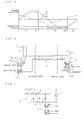
- Fig. 1 is a circuit diagram of the configuration of a capacitor drop type power supply circuit according to an embodiment mode of the present invention.
- the capacitor drop type power supply circuit of this embodiment mode is configured as follows. That is, an AC power supply 1 is connected with a series-circuit of a resistor 2, a first capacitor 3, and a first diode 4 that is cathode-connected to the first capacitor 3.
- the first diode 4 is parallel-connected to a series circuit of a second diode 5 and a Zener diode 6.
- the Zener diode 6 is parallel-connected to a second capacitor 7 (smoothing capacitor).
- a DC voltage across the second capacitor 7 is outputted to a communication circuit 8.
- the above resistor 2 controls a surge current at power-on, and the first capacitor 3 controls a current at normal time.
- the first diode 4 functions to discharge a charge accumulated in the first capacitor 3 as detailed in the following description about operations, and the second diode 5 carries out half-wave rectification of a power supply voltage from the AC power supply 1.
- FIGs. 2(1) to 2(4) are explanatory views showing operations of the capacitor drop type power supply circuit of this embodiment mode in accordance with energization patterns.
- Fig. 3 is a waveform diagram showing waveforms of each portion in accordance with energization patterns.
- a power supply voltage Vs of the AC power supply 1 is higher than the total value of a voltage Vc of the first capacitor 3 and a Zener voltage Vd of the Zener diode 6, as shown in Fig. 2(1), a power supply current Is flows from the AC power supply 1 through the resistor 2 and the first capacitor 3. After the half-wave rectification with the second diode 5, the current flows into the Zener diode 6. Then, the Zener voltage Vd (24 V) is generated across the diode and charges the second capacitor 7.
- the voltage Vc of the first capacitor 3 is determined by subtracting the Zener voltage Vd from the power supply voltage Vs as given by Expression (2).
- the voltage Vc has a waveform of Fig. 3(1). In this case, the power supply voltage Vs in a range defined by Expression (3) satisfies Expression (2).
- Vc t Vs t - Vd - V peak + Vd ⁇ Vs t ⁇ Vs peak
- Vc t Vs t - Vs peak ⁇ Vs t ⁇ Vs peak
- the current Is is determined by differentiating the voltage Vc of the first capacitor 3 and multiplying the calculated value by a capacitance C of the first capacitor, on the basis of Expression (11) below.
- the first diode 4 cathode-connected to the first capacitor 3 is provided in the series circuit connected to the AC power supply 1, so a surge current generated at power-on may be allowed to flow into the first diode 4.
- a surge current generated at power-on may be allowed to flow into the first diode 4.
- Fig. 4 is a circuit diagram showing serial communications of an air conditioner according to the embodiment of the present invention.
- Fig. 5 is a circuit diagram showing connection between the capacitor drop type power supply circuit and a communication circuit provided in an outdoor unit of an air conditioner. Incidentally, the configuration of the capacitor drop type power supply circuit is the same as that of the embodiment mode, so description thereof is omitted here.
- a capacitor drop type power supply circuit 9 is connected to power supply lines 12 for supplying an AC power 1 to an outdoor unit and an indoor unit, on its input side.
- a communication circuit 10 of the outdoor unit includes a photo-coupler 10a on the transmission side is connected to an output end (positive side) of the capacitor drop type power supply circuit 9, and a photo-coupler 10b on the reception side, which is connected to the photo-coupler 10a is connected to a photo-coupler 11a on the reception side of the communication circuit 11 provided in the indoor unit through a communication line 13.
- a photo-coupler 11b on the transmission side, which is connected to the photo-coupler 11a is connected to one of the power supply lines 12 (on the ground side).
- a DC voltage of the capacitor drop type power supply circuit 9 is applied to the communication circuit 10 of the outdoor unit and the communication circuit 11 of the indoor unit to thereby realize serial communications between the photo-couplers 10a, 10b, 11a, and 11b.
- control circuits for example, microcomputers incorporated in both of the indoor unit and the outdoor unit are insulated from the DC voltage of the power supply circuit 9 by means of the photo-couplers 10a and 10b of the communication circuit 10 and the photo-couplers 11a and 11b of the communication circuit 11.
- the AC power supply 1 has a power of 180 to 264 V
- the resistor 2 has a resistance of 47 ⁇
- the first capacitor 3 has a capacitance of 1 ⁇ F
- the first diode 4 has a surge current of 30 A
- the second diode 5 has a surge current of 30 A
- the Zener diode 6 has a voltage of 24 V
- the second capacitor 7 has a capacitance of 470 ⁇ F.
- the surge current of the first and second diodes is 30 A
- the surge current of 30 A or less is attained if a resistance value of the resistor 2 is 8.8 ⁇ or more.
- a resistance are set to 47 ⁇ with regard for a margin of components, so that the surge current is suppressed to 8 A.
- a circuit with a relatively small capacity is used as a power supply, and the power supply circuit can be manufactured at low cost with a small number of components. An output efficiency is also 1 W or less, so power consumption can be considerably reduced. Further, the capacitor drop type power supply circuit 9 is used as a power supply for serial communications between the indoor unit and the outdoor unit, so standby power consumption during a period in which the air conditioner stops operations can be suppressed.
Landscapes
- Engineering & Computer Science (AREA)
- Power Engineering (AREA)
- Rectifiers (AREA)
- Air Conditioning Control Device (AREA)
- Direct Current Feeding And Distribution (AREA)
Applications Claiming Priority (1)
| Application Number | Priority Date | Filing Date | Title |
|---|---|---|---|
| JP2006317059A JP2008131822A (ja) | 2006-11-24 | 2006-11-24 | コンデンサドロップ式電源回路及び空気調和機 |
Publications (2)
| Publication Number | Publication Date |
|---|---|
| EP1926201A2 true EP1926201A2 (fr) | 2008-05-28 |
| EP1926201A3 EP1926201A3 (fr) | 2009-10-14 |
Family
ID=39271325
Family Applications (1)
| Application Number | Title | Priority Date | Filing Date |
|---|---|---|---|
| EP07022123A Withdrawn EP1926201A3 (fr) | 2006-11-24 | 2007-11-14 | Circuit d'alimentation de type condensateur de chute et climatiseur |
Country Status (3)
| Country | Link |
|---|---|
| US (1) | US20080180978A1 (fr) |
| EP (1) | EP1926201A3 (fr) |
| JP (1) | JP2008131822A (fr) |
Families Citing this family (5)
| Publication number | Priority date | Publication date | Assignee | Title |
|---|---|---|---|---|
| JP5630776B2 (ja) * | 2008-07-25 | 2014-11-26 | ダイヤモンド電機株式会社 | 電力機器の駆動制御装置 |
| CN102790538B (zh) * | 2011-05-19 | 2015-09-30 | 深圳长城开发科技股份有限公司 | 电能表及其rc电源 |
| WO2017011008A1 (fr) * | 2015-07-15 | 2017-01-19 | Hewlett-Packard Development Company, L.P. | Alimentation d'un dispositif de surveillance d'énergie |
| CN106610081B (zh) * | 2015-10-22 | 2019-08-20 | 上海三菱电机·上菱空调机电器有限公司 | 一种空调机连续运转的方法 |
| CN111043721B (zh) * | 2019-12-09 | 2020-11-24 | 珠海格力电器股份有限公司 | 一种can总线匹配电阻接入方法、装置、空调机组及系统 |
Citations (1)
| Publication number | Priority date | Publication date | Assignee | Title |
|---|---|---|---|---|
| JP2000209865A (ja) | 1999-01-08 | 2000-07-28 | Fuji Electric Co Ltd | 高圧パルス発生装置 |
Family Cites Families (5)
| Publication number | Priority date | Publication date | Assignee | Title |
|---|---|---|---|---|
| IL75172A0 (en) * | 1985-05-12 | 1985-09-29 | Howard Michael S | Ballasts and transformerless power supplies |
| GB9703088D0 (en) * | 1997-02-14 | 1997-04-02 | Switched Reluctance Drives Ltd | Power supply circuit for a control circuit |
| ES2203951T3 (es) * | 1997-05-20 | 2004-04-16 | Daikin Industries, Ltd. | Rectificador monofasico. |
| JP4288831B2 (ja) * | 2000-06-14 | 2009-07-01 | 三菱電機株式会社 | セパレート形空気調和機の制御回路 |
| JP4543718B2 (ja) * | 2003-11-27 | 2010-09-15 | ダイキン工業株式会社 | 電力変換装置 |
-
2006
- 2006-11-24 JP JP2006317059A patent/JP2008131822A/ja active Pending
-
2007
- 2007-11-14 EP EP07022123A patent/EP1926201A3/fr not_active Withdrawn
- 2007-11-21 US US11/984,752 patent/US20080180978A1/en not_active Abandoned
Patent Citations (1)
| Publication number | Priority date | Publication date | Assignee | Title |
|---|---|---|---|---|
| JP2000209865A (ja) | 1999-01-08 | 2000-07-28 | Fuji Electric Co Ltd | 高圧パルス発生装置 |
Also Published As
| Publication number | Publication date |
|---|---|
| JP2008131822A (ja) | 2008-06-05 |
| EP1926201A3 (fr) | 2009-10-14 |
| US20080180978A1 (en) | 2008-07-31 |
Similar Documents
| Publication | Publication Date | Title |
|---|---|---|
| US6703793B2 (en) | Switching power unit | |
| US9413262B2 (en) | Smart power adaptor and method for controlling power supplay thereof | |
| US9603205B2 (en) | Multi-function terminal configurable to implement two functionalities | |
| CN111262420B (zh) | Ac/dc电源、整流电路及其控制方法 | |
| EP1926201A2 (fr) | Circuit d'alimentation de type condensateur de chute et climatiseur | |
| GB2468000A (en) | Over-current protection circuit and motor controller | |
| CN210724722U (zh) | 热插拔控制电路 | |
| WO2004047249A3 (fr) | Circuit integre de controle pour les alimentations en puissance auxiliaires | |
| US7412305B2 (en) | Power supply detection device and method | |
| US8669749B2 (en) | Switching power supply unit | |
| EP1782516A2 (fr) | Alimentation a resistances en echelle avec protection contre la surtension | |
| CN107968555A (zh) | 一种用于高压输入的耐压电路及开关电路 | |
| US20140035475A1 (en) | Controller of an ac-dc converter for led lighting | |
| JP6710868B2 (ja) | 送信装置、受信装置、監視装置および太陽光発電システム | |
| EP1693949B1 (fr) | Appareil de conversion d'energie electrique | |
| JP5589143B2 (ja) | 補助電源ユニット用制御回路、及び電源ユニット装置 | |
| CN117559766A (zh) | 母线电压控制电路、芯片、交流-直流电源、设备及方法 | |
| WO2014013854A1 (fr) | Etiquette de capteur et module d'alimentation à collecte d'énergie | |
| KR20080009895A (ko) | 평활용 커패시터의 충전 및 방전 회로 | |
| CN108322035B (zh) | 一种充电控制电路及其控制方法 | |
| JP5758208B2 (ja) | 電力線伝送用デバイス | |
| KR102049965B1 (ko) | 대기 전력 절감 기능을 구비하는 정류 장치 | |
| CN218499029U (zh) | 开关电源、交流-直流电路及输入电压检测电路 | |
| US20250183787A1 (en) | Power supply unit and adjustment method for over-power protection value thereof | |
| CN222127705U (zh) | 负载保护电路、负载供电电路和监控设备 |
Legal Events
| Date | Code | Title | Description |
|---|---|---|---|
| PUAI | Public reference made under article 153(3) epc to a published international application that has entered the european phase |
Free format text: ORIGINAL CODE: 0009012 |
|
| AK | Designated contracting states |
Kind code of ref document: A2 Designated state(s): AT BE BG CH CY CZ DE DK EE ES FI FR GB GR HU IE IS IT LI LT LU LV MC MT NL PL PT RO SE SI SK TR |
|
| AX | Request for extension of the european patent |
Extension state: AL BA HR MK RS |
|
| PUAL | Search report despatched |
Free format text: ORIGINAL CODE: 0009013 |
|
| AK | Designated contracting states |
Kind code of ref document: A3 Designated state(s): AT BE BG CH CY CZ DE DK EE ES FI FR GB GR HU IE IS IT LI LT LU LV MC MT NL PL PT RO SE SI SK TR |
|
| AX | Request for extension of the european patent |
Extension state: AL BA HR MK RS |
|
| 17P | Request for examination filed |
Effective date: 20091117 |
|
| 17Q | First examination report despatched |
Effective date: 20091211 |
|
| AKX | Designation fees paid |
Designated state(s): ES IT |
|
| REG | Reference to a national code |
Ref country code: DE Ref legal event code: 8566 |
|
| STAA | Information on the status of an ep patent application or granted ep patent |
Free format text: STATUS: THE APPLICATION IS DEEMED TO BE WITHDRAWN |
|
| 18D | Application deemed to be withdrawn |
Effective date: 20100422 |