EP1926660B1 - Bord de fuite progressiste d'aile d'avion - Google Patents
Bord de fuite progressiste d'aile d'avion Download PDFInfo
- Publication number
- EP1926660B1 EP1926660B1 EP06805758A EP06805758A EP1926660B1 EP 1926660 B1 EP1926660 B1 EP 1926660B1 EP 06805758 A EP06805758 A EP 06805758A EP 06805758 A EP06805758 A EP 06805758A EP 1926660 B1 EP1926660 B1 EP 1926660B1
- Authority
- EP
- European Patent Office
- Prior art keywords
- flap
- trailing edge
- wing
- advanced trailing
- advanced
- Prior art date
- Legal status (The legal status is an assumption and is not a legal conclusion. Google has not performed a legal analysis and makes no representation as to the accuracy of the status listed.)
- Not-in-force
Links
- 238000007789 sealing Methods 0.000 claims description 63
- 230000007246 mechanism Effects 0.000 claims description 43
- 238000009423 ventilation Methods 0.000 claims description 33
- 230000008878 coupling Effects 0.000 claims description 9
- 238000010168 coupling process Methods 0.000 claims description 9
- 238000005859 coupling reaction Methods 0.000 claims description 9
- RZVHIXYEVGDQDX-UHFFFAOYSA-N 9,10-anthraquinone Chemical compound C1=CC=C2C(=O)C3=CC=CC=C3C(=O)C2=C1 RZVHIXYEVGDQDX-UHFFFAOYSA-N 0.000 claims description 5
- 230000003044 adaptive effect Effects 0.000 claims description 5
- 238000010276 construction Methods 0.000 claims description 5
- 230000001965 increasing effect Effects 0.000 claims description 4
- 230000000694 effects Effects 0.000 description 5
- 230000000750 progressive effect Effects 0.000 description 4
- 208000010201 Exanthema Diseases 0.000 description 3
- 201000005884 exanthem Diseases 0.000 description 3
- 206010037844 rash Diseases 0.000 description 3
- 238000000926 separation method Methods 0.000 description 3
- 230000002349 favourable effect Effects 0.000 description 2
- 230000002411 adverse Effects 0.000 description 1
- 230000005540 biological transmission Effects 0.000 description 1
- 238000000354 decomposition reaction Methods 0.000 description 1
- 230000003111 delayed effect Effects 0.000 description 1
- 238000011161 development Methods 0.000 description 1
- 230000018109 developmental process Effects 0.000 description 1
- 238000004146 energy storage Methods 0.000 description 1
- 230000002708 enhancing effect Effects 0.000 description 1
- 210000003746 feather Anatomy 0.000 description 1
- 239000000446 fuel Substances 0.000 description 1
- 230000001771 impaired effect Effects 0.000 description 1
- 238000013022 venting Methods 0.000 description 1
Images


Classifications
-
- B—PERFORMING OPERATIONS; TRANSPORTING
- B64—AIRCRAFT; AVIATION; COSMONAUTICS
- B64C—AEROPLANES; HELICOPTERS
- B64C9/00—Adjustable control surfaces or members, e.g. rudders
- B64C9/14—Adjustable control surfaces or members, e.g. rudders forming slots
-
- B—PERFORMING OPERATIONS; TRANSPORTING
- B64—AIRCRAFT; AVIATION; COSMONAUTICS
- B64C—AEROPLANES; HELICOPTERS
- B64C9/00—Adjustable control surfaces or members, e.g. rudders
- B64C9/14—Adjustable control surfaces or members, e.g. rudders forming slots
- B64C9/16—Adjustable control surfaces or members, e.g. rudders forming slots at the rear of the wing
- B64C9/18—Adjustable control surfaces or members, e.g. rudders forming slots at the rear of the wing by single flaps
-
- Y—GENERAL TAGGING OF NEW TECHNOLOGICAL DEVELOPMENTS; GENERAL TAGGING OF CROSS-SECTIONAL TECHNOLOGIES SPANNING OVER SEVERAL SECTIONS OF THE IPC; TECHNICAL SUBJECTS COVERED BY FORMER USPC CROSS-REFERENCE ART COLLECTIONS [XRACs] AND DIGESTS
- Y02—TECHNOLOGIES OR APPLICATIONS FOR MITIGATION OR ADAPTATION AGAINST CLIMATE CHANGE
- Y02T—CLIMATE CHANGE MITIGATION TECHNOLOGIES RELATED TO TRANSPORTATION
- Y02T50/00—Aeronautics or air transport
- Y02T50/30—Wing lift efficiency
-
- Y—GENERAL TAGGING OF NEW TECHNOLOGICAL DEVELOPMENTS; GENERAL TAGGING OF CROSS-SECTIONAL TECHNOLOGIES SPANNING OVER SEVERAL SECTIONS OF THE IPC; TECHNICAL SUBJECTS COVERED BY FORMER USPC CROSS-REFERENCE ART COLLECTIONS [XRACs] AND DIGESTS
- Y02—TECHNOLOGIES OR APPLICATIONS FOR MITIGATION OR ADAPTATION AGAINST CLIMATE CHANGE
- Y02T—CLIMATE CHANGE MITIGATION TECHNOLOGIES RELATED TO TRANSPORTATION
- Y02T50/00—Aeronautics or air transport
- Y02T50/40—Weight reduction
Definitions
- the present invention relates to an advanced wing trailing edge on the wing of an aircraft.
- ATECS Advanced Trailing Edge Control Surfaces
- the lower venting flap of the patents mentioned here is usually designed only for positive flap deflections ( US2117607 . US2169416 ).
- the mechanical connection between lower ventilation flap and flap is realized either by a mechanical forced coupling or via another drive.
- Another known flap system ( DE1943680 ) has both a lower and upper vent flap, which can handle positive and negative flap deflections.
- a major disadvantage of this concept is that the ventilation flaps leave the outer wing profile contour (resistance, noise). It is a symmetrical and clamp-sensitive construction which exploits the advantageous technical effect of the gap in both directions.
- An adaptive wing typically requires other complex systems that often collide with the existing primary and secondary control surfaces. Further drives, a high number of parts, flexible structures and additional control circuits with the corresponding sensors are necessary. By way of example, two named systems for adjusting the entire airfoil or profile pressure curve are mentioned ( DE19732953C1 . DE60002851T2 ).
- a wing flap assembly in which in the extension of a profile (wing or tail), a control flap is pivotally mounted about an axis by means of a drive.
- the axis extending in the spanwise direction can in principle be moved in the direction of the profile to or away from it by a further drive.
- cover flaps To cover the gap between the profile and the control flap serve two cover flaps. These are pivotable about each profile-fixed axes by means of an integrally formed pivoting arm, wherein their actuation is derived directly from the control flap via two coupling.
- the object of the present invention is to provide a blade trailing edge in which both primary and secondary control surfaces are realized on the wing with less mechanical effort and less weight.
- the invention provides an advanced wing trailing edge on the wing of an aircraft, having a wing, a spanwise span extending flap adjustable at the trailing edge of the wing, one at the top between arranged pivotally movable sealing flap arranged on the wing and the flap and a pivotally movable ventilation flap arranged on the underside between the wing and the flap.
- the flap is adjustable both on positive flap deflections down and negative flap deflections, wherein for use of the flap as a control valve with settings of the flap between negative and small positive flap deflections the wing profile at the top through the Abdichtklappe and the bottom is closed by the ventilation flap and for using the flap as a lift increasing flap with settings of the flap between small positive and large positive flap deflections the vent flap a flow from the underside of the wing to the top of the flap releases and the Abdichtklappe to release an outflow from the top of the flap is removed by a predetermined gap.
- the sealing flap for use as a brake flap with its rear end is pivotable upwards.
- the sealing flap is forcibly guided with the flap.
- a flap guide mechanism which comprises by a arranged between the wing and the flap pivot.
- the fulcrum of the hinge is positioned so that for negative flap deflections of the flap, the wing profile contour is not left and for positive flap deflections of the flap, a substantial area and Völbungsveriererung is achieved.
- the drive for the flap guide mechanism is formed by a linear thrust element, which is coupled to the wing and the flap.
- the pusher element includes an actuator.
- the actuator can be operated hydraulically (hydraulic actuator) or mechanically (spindle drive).
- the flap is mechanically positively driven or positively coupled with the ventilation flap.
- a ventilation flap mechanism in which the ventilation flap is connected to the wing by means of a stationary bearing and a bearing lever mechanism containing two levers.
- a sealing flap mechanism is provided in which the sealing flap is positively guided with the flap.
- the sealing flap is positively urged through the flap by a lever mechanism coupled to the flap via a proximate bearing at a second bearing to the flap and proximate to a fourth bearing via a third bearing.
- the lever mechanism containing the coupling rod and connecting the sealing flap to the flap preferably forms a four-bar linkage.
- the fourth bearing is entrained upon movement of the sealing flap in the sense of a brake flap function.
- a further bearing is provided on the upper sealing flap, with which an actuator for actuating the sealing flap is coupled in the sense of a brake flap function.
- the further bearing is arranged on a common axis of rotation with the fourth bearing.
- the sealing flap mechanism is configured to avoid collision between the flap and the sealing flap for small positive flap angles up to all negative flap angles of the flap and to seal the sealing flap against the flap throughout the range just mentioned.
- the upper sealing flap is lowered in the sense of creating a convergent aerodynamic gap by rotation about the fourth bearing.
- a functional relationship between the absolute flap angle of the upper sealing flap (relative to the fixed wing 1) and the flap angle of the flap is made by a corresponding regulation in the flight control computer.
- the actuator device provided for the brake flap function moves the element via the further bearing about a bearing on a circular path, whereby the double joint formed by the fourth joint and the further joint also moves on this circular path.
- the brake flap mechanism is largely decoupled from the upper sealing mechanism.
- the brake flap mechanism can not be integrated into the kinematic system but can be provided separately.
- all bearings are simple hinges.
- the construction consists essentially of rods and trusses.
- kinematics is provided in a three-dimensional design for a cylindrical movement of the flap.
- the kinematics is provided in a three-dimensional design for a conical movement of the flap.
- the advanced blade trailing edge can serve as the primary control surface.
- the advanced blade trailing edge can serve as a secondary control surface.
- the advanced wing trailing edge can serve as an adaptive wing component.
- the advanced wing trailing edge of the present invention is advantageously provided for use at the trailing edge of trailing wings in modern commercial and high takeoff weight transport aircraft.
- the advanced wing trailing edge of the present invention is advantageously characterized by low weight, high reliability, a small number of parts, and a structurally simple construction.
- the complex demands on an advanced wing trailing edge concept were realized in the best possible way.
- the entire supporting structures and the kinematic system of a conventional high-lift system are eliminated.
- the aerodynamic fairing is significantly smaller with the advanced wing trailing edge, which will provide an overall economic advantage for the entire cruise (low drag, low fuel cost).
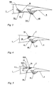
- the advanced wing trailing edge on the wing of an aircraft is in its entirety in FIG. 1 shown schematically.
- the following nomenclature is used to understand the kinematic sketch. Individual kinematic elements are numbered consecutively and the connection joints between two parts are each characterized by the two numbers of the respective elements (eg: element 1 and element 5 are connected by a hinge 15, mutatis mutandis, the other fasteners arise).
- the advanced wing trailing edge comprises a wing 1, arranged at the trailing edge of the wing 1, extending in the spanwise direction, adjustable to different deflections flap 4, which can be effective both as a control valve and as a lift-increasing flap. This is always referred to as "flap" in the following.
- a strict separation between control surface (primary control surface) and high-lift component (secondary control surface) in the conventional sense is no longer appropriate, but both functions can more or less seamlessly merge into each other.
- a sealing flap 5 is pivotally movable and arranged on the underside between the wing 1 and the flap 4 is a ventilation flap 5 also pivotally movable.
- the flap 4 (the reference numerals are in the FIGS. 6a ) to e) omitted for the purpose of clarity, see.
- the reference numerals in FIGS. 1 to 5 adjustable over both positive flap deflections downwards and negative flap deflections upwards.
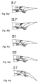
- the flap 4 As a control flap with settings of the flap between negative ( FIG. 6b )) and small positive valve rashes ( FIG. 6d )), the wing profile is closed at the top by a sealing flap 7 and at the bottom by a ventilation flap 5.
- the flap 4 as lift-increasing flap with settings of the flap 4 between small positive flap deflections ( FIG.
- the ventilation flap 5 releases a flow from the underside of the wing 1 to the top of the flap 4 and the sealing flap 7 is removed to release an outflow from the top of the flap 4 by a predetermined gap.
- FIGS. 2 to 5 Since the mechanism of the progressive wing trailing edge in the entire representation is somewhat confusing, is in the FIGS. 2 to 5 a decomposition of the entire mechanism into its four sub-mechanisms.
- the four sub-mechanisms are a flapper guide mechanism, a lower vent flap mechanism, an upper flapper mechanism, and a brake flap mechanism. These individual mechanisms can be found in their entirety in FIG. 1 again.
- the flap guide mechanism which stands for itself in FIG. 2 is shown, it is primarily essentially a simple hinge joint, ie it is only a pivot joint 14 is required, which represents the connection between the wing 1 and the flap 4.
- the wing 1 is from a kinematic perspective, the stationary frame.
- the pivot point 14 is positioned so that for negative flap deflections of the flap 4, the wing profile contour is not left and yet as much area and Völbungsver employedrung for positive flap deflections of the flap 4 is achieved.
- the drive is realized by a linear sliding joint 23, which is rotatably mounted with the wing 1 and the flap 4 at the ends of the respective actuator element.
- the actuator consists of parts 2 and 3 and can be operated either hydraulically (hydraulic actuator) or mechanically (spindle drive).
- the ventilation flap mechanism is basically in FIG. 3 schematically.
- the fixed wing 1 is visible with the fixed bearings 15 and 14.
- the flap 4 and the ventilation flap 5 is connected.
- the function of the ventilation flap 5 has already been mentioned above, but will be briefly explained again for clarity.
- the function of the ventilation flap allows for larger flap angle of the flap 4, see FIG. 6e ), a sufficient flow around the flap 4 with high-energy air, so that more buoyancy occurs and the separation behavior of the flow is delayed.
- the flap 4 is forced mechanically coupled with the ventilation flap 5 or positively coupled, ie there is a clear functional dependence between these two elements.
- the mechanical coupling is realized by a simple rod 6. All bearings are simple hinges in the two-dimensional sketch, in a three-dimensional design, this may be analogous to other joints, for example, ball joints with three rotational degrees of freedom. The mechanical principle remains unchanged in the three-dimensional space, therefore, a two-dimensional representation is sufficient.
- the hinges 15, 14, 56 and 46 are therefore simple hinges in the two-dimensional drawing. Overall, therefore, the forced coupling is realized by the simplest conceivable mechanism (four-bar linkage).
- the lower ventilation flap 5 opens in the direction of the wing contour to the intended opening angle.
- the dimensions of the ventilation flap 5 and the opening angle are determined by the aerodynamic boundary conditions (maximum lift, low air resistance, low noise emissions, etc ).
- the ventilation flap 5 For smaller positive and all negative flap angle of the flap 4, the ventilation flap 5 remains almost in its nominal position.
- the nominal position in this case is characterized by the profile contour in cruising flight. It is thus a "quasi" rest in the range of small positive to large negative flap deflections of the flap 4 by an advantageous technical design of the transmission gear (the aforementioned four-bar linkage) achieved.
- a complete seal the ventilation flap to the flap 4 guaranteed, thereby the profile contour always aerodynamic (low air resistance) and harmful noise sources in the form of edges, profile contour jumps Leewirbel whichen be avoided.
- the sealing flap mechanism is basically in FIG. 4 schematically.
- the stationary wing 1 can be seen with the stationary bearing 14.
- the flap 4 is connected.
- a bearing 79 is only fixed to the wing 1, if the brake flap function of the upper sealing flap 7 is not driven.
- the bearing 79 and another bearing 910 are on a common axis of rotation, so this is a kind of double joint.
- the bearing 79 is stationary to the wing 1.
- the functions of the upper sealing flap 7 will be shown in detail below. Due to the demand to allow negative flap deflections of the flap 4, it is necessary to raise the upper wing contour or the air brakes normally located at this point on commercial aircraft to a collision of the sealing flap 7 (the sealing flap 7 is also the same time the brake flap, see the following) to avoid with the flap 4.
- a mechanical coupling rod 8 connects the sealing flap 7 and the flap 4.
- the brake flap mechanism operates almost completely mechanically decoupled from the flap mechanism, there is only a functional dependence between the absolute brake flap deflection of the upper sealing flap 7 (relative to the stationary wing 1) and the flap deflection angle of the flap 4, this is taken into account by a corresponding regulation in the flight control computer.
- This regulation does not affect the Abdichtklappenmechanismus (except in case of failure), because the aerodynamic gap is abandoned in the brake flap mode with corresponding loss of lift and increase in air resistance.
- the normal brake flap functions can thus be generated unchanged by a further drive (element 10 and element 11), without the above-mentioned mechanism of the lower panel (ventilation flap) 5 and the upper panel (sealing flap) 7 would be impaired in its operation.
- the typical brake flap acts as an air brake, buoyancy regulator, roll control and wing relief.
- FIG. 5 the additional kinematic elements are shown, which also enable the brake flap function for the upper sealing flap 7. Consequently, the upper sealing flap also acts as a brake flap. Furthermore, the brake flap function is actuated by its own drive.
- the actuator device consists of the parts 10 (actuator) and 11 (actuator rod) and can be operated hydraulically (hydraulic actuator) or mechanically (spindle drive).
- the actuator device of the brake flap function moves the element 9 via the bearing 910 to a bearing 19 on a circular path.
- the movement of the element 9 on the circular path has the consequence that the double joint 79 also moves on this circular path.
- the sealing flap 7 (if it is active as a brake flap) thus moves on the coupling of the four-bar linkage 48, 78, 79 and 19.
- the bearing 19 is placed in an advantageous manner so that there is no collision with the wing 1.
- the brake flap mechanism can not be integrated into the kinematic system but can be provided separately, this would be conceivable in the outer wing area as ailerons.
- the aerodynamic flap gap is held exactly by a mechanical positive guidance to the flap 4, there is no complex control loop to keep the flap gap (aerodynamic Air gap tolerances) necessary. Only the actuator for the flap 4 (actuator body 2 and actuator rod 3) accomplishes these functions. For larger positive flap angle of the flap 4 pivots the lower vent flap 5 in the wing profile contour and the advantageous flow around the flap 4 is achieved.
- the upper sealing flap 7 acts from larger flap angles of the flap 4 no longer as a seal, but must keep the aerodynamic Strömungsververgenz and the aerodynamic gap exactly, see FIG. 6e ): TAB 35 °, A / B 0 °).
- both a primary and a secondary flight control can be effected. Ie. high actuating speeds for primary control surfaces can be realized.
- the wing trailing edge according to the invention can act as an adaptive wing, by small positive or negative stationary flap deflections can always be the most economical operating point for the respective altitude (density, temperature, etc ..), The loading state and the airspeed.
- the airfoil contour remains closed (except in the airbrake mode) and the protil shape remains aerodynamically aerodynamically favorable. In conventional secondary high lift systems this was i. d. R. not possible, because negative flap deflections could not be realized.
- the brake flap mode of the upper sealing flap 7, which acts here as a brake flap, is for better understanding in the FIGS. 7a ) to c) in various configurations (TAB -20 °, A / B 40 °, TAB 0 °, A / B 40, TAB 35 °, A / B 40 °).
Landscapes
- Engineering & Computer Science (AREA)
- Aviation & Aerospace Engineering (AREA)
- Air-Flow Control Members (AREA)
- Braking Arrangements (AREA)
- Transmission Devices (AREA)
Claims (30)
- Bord de fuite évolué sur l'aile d'un avion, comprenant une aile (1), un volet (4) disposé sur le bord de fuite de l'aile (1), s'étendant dans la direction de l'envergure et réglable sur des débattements différents, un volet d'étanchéité (7) mobile pivotant, disposé sur le côté supérieur entre l'aile (1) et le volet (4), et un volet d'aération (5) mobile pivotant, disposé sur le côté inférieur entre l'aile (1) et le volet (4), le volet (4) étant réglable aussi bien vers le bas par l'intermédiaire de débattements positifs que vers le haut par l'intermédiaire de débattements négatifs, caractérisé en ce que, pour une utilisation du volet (4) en tant que volet de commande avec des réglages du volet entre des débattements négatifs et de faibles débattements positifs, le profil d'aile est fermé sur le côté supérieur par le volet d'étanchéité (7) et sur le côté inférieur par le volet d'aération (5) et, pour une utilisation du volet (4) en tant que volet hypersustentateur avec des réglages du volet (4) entre de faibles débattements positifs et des débattements positifs élevés, le volet d'aération (5) libère un écoulement du côté inférieur de l'aile (1) en direction du côté supérieur du volet (4) et le volet d'étanchéité (7) est écarté pour produire une déflexion du côté supérieur du volet (4) autour d'une fente prédéfinie.
- Bord de fuite évolué suivant la revendication 1, caractérisé en ce que le volet d'étanchéité (7) peut pivoter vers le haut par son extrémité arrière pour l'utilisation en tant que frein aérodynamique.
- Bord de fuite évolué suivant l'une des revendications 1 ou 2, caractérisé en ce que le volet d'étanchéité (7) est à guidage forcé avec le volet (4).
- Bord de fuite évolué suivant l'une des revendications 1, 2 ou 3, caractérisé en ce qu'il est prévu un mécanisme de guidage de volet, qui comporte une articulation à charnière (14) disposée entre l'aile (1) et le volet (4).
- Bord de fuite évolué suivant l'une des revendications 1, 2, 3 ou 4, caractérisé en ce que le centre de rotation de l'articulation à charnière (14) est positionné de sorte que, pour des débattements négatifs du volet (4), le contour du profil d'aile n'est pas quitté et, pour des débattements positifs du volet (4), une augmentation significative de surface et de courbure est obtenue.
- Bord de fuite évolué suivant l'une des revendications 1 à 5, caractérisé en ce que l'entraînement pour le mécanisme de guidage du volet est formé par un élément de poussée linéaire (23), qui est couplé à l'aile (1) et au volet (4).
- Bord de fuite évolué suivant la revendication 6, caractérisé en ce que l'élément de poussée (23) comporte un vérin (2, 3).
- Bord de fuite évolué suivant la revendication 7, caractérisé en ce que le vérin (2, 3) fonctionne par voie hydraulique (vérin hydraulique) ou par voie mécanique (actionneur à vérin à vis).
- Bord de fuite évolué suivant l'une des revendications 1 à 8, caractérisé en ce que le volet (4) est à guidage et/ou à couplage forcé mécanique avec le volet d'aération (5).
- Bord de fuite évolué suivant la revendication 9, caractérisé en ce qu' il est prévu un mécanisme de volet d'aération, dans lequel le volet d'aération (5) est rattaché à l'aile (1) par l'intermédiaire d'un mécanisme à levier monté sur des paliers fixes (15) et (14) et comportant deux leviers (barres 5, 6).
- Bord de fuite évolué suivant l'une des revendications 1 à 10, caractérisé en ce qu'il est prévu un mécanisme de volet d'étanchéité, dans lequel le volet d'étanchéité (7) est à guidage forcé avec le volet (4).
- Bord de fuite évolué suivant la revendication 11, caractérisé en ce que, dans le mécanisme de volet d'étanchéité, le volet d'étanchéité (7) est à guidage forcé par le volet (4) par un mécanisme à levier, couplé au volet (4) par l'intermédiaire d'un deuxième palier (48) au voisinage du palier fixe (14), et au volet d'étanchéité (7), au voisinage d'un quatrième palier (79), par l'intermédiaire d'un troisième palier (78).
- Bord de fuite évolué suivant la revendication 12, caractérisé en ce que le mécanisme à levier, qui comporte la barre d'accouplement (8) et relie le volet d'étanchéité (7) avec le volet (4), forme un quadrilatère articulé (paliers 79, 78, 48, 14)
- Bord de fuite évolué suivant l'une des revendications 12 ou 13, caractérisé en ce que le quatrième palier (79) est entraîné lors du déplacement du volet d'étanchéité (7) dans le sens d'une fonction de frein aérodynamique.
- Bord de fuite évolué suivant l'une des revendications 13 ou 14, caractérisé en ce qu'il est prévu un palier supplémentaire (910) sur le volet d'étanchéité supérieur (7), auquel est couplé un vérin (10, 11) pour l'actionnement du volet d'étanchéité (7) dans le sens d'une fonction de frein aérodynamique.
- Bord de fuite évolué suivant la revendication 15, caractérisé en ce que le palier supplémentaire (910) est disposé sur un axe de rotation commun avec le quatrième palier (79)
- Bord de fuite évolué suivant l'une des revendications 11 à 16, caractérisé en ce que le mécanisme de volet d'étanchéité est réalisé de sorte que, pour de petits angles de débattement positifs jusqu'à tous les angles de débattement négatifs du volet (4), une collision est évitée entre le volet (4) et le volet d'étanchéité (7) et le volet d'étanchéité (7) est étanchéifié par rapport au volet (4) dans toute la zone justement mentionnée.
- Bord de fuite évolué suivant la revendication 17, caractérisé en ce que, pour des débattements positifs relativement élevés du volet (4), où le volet (4) agit en tant que composant hypersustentateur, le volet d'étanchéité (7) supérieur est abaissé vers le bas par rotation autour du quatrième palier (79) dans le sens d'une production d'une fente aérodynamique convergente.
- Bord de fuite évolué suivant l'une des revendications 11 à 18, caractérisé en ce qu'une relation fonctionnelle entre le débattement absolu de frein aérodynamique du volet d'étanchéité supérieur (7) (par rapport à l'aile 1 fixe) et l'angle de débattement du volet (4) est assurée par un réglage approprié dans l'ordinateur de commande de vol.
- Bord de fuite évolué suivant l'une des revendications 11 à 19, caractérisé en ce que le système de vérin (10, 11), prévu pour la fonction de frein aérodynamique, déplace sur une orbite l'élément (9) par l'intermédiaire du palier supplémentaire (910) autour d'un palier (19), la double articulation, formée par la quatrième articulation (79) et l'articulation supplémentaire (913), se déplaçant également de ce fait sur cette orbite.
- Bord de fuite évolué suivant l'une des revendications 11 à 20, caractérisé en ce que le mécanisme de frein aérodynamique est sensiblement découplé du mécanisme d'étanchéité supérieur.
- Bord de fuite évolué suivant l'une des revendications 11 à 14, caractérisé en ce que le mécanisme de frein aérodynamique n'est pas intégré dans le système cinématique mais est prévu séparément.
- Bord de fuite évolué suivant l'une des revendications 1 à 22, caractérisé en ce que tous les paliers sont de simples articulations à charnière.
- Bord de fuite évolué suivant l'une des revendications précédentes, caractérisé en ce que la construction est essentiellement constituée uniquement de barres et de treillis.
- Bord de fuite évolué suivant l'une des revendications 1 à 24, caractérisé en ce que la cinématique est prévue dans une réalisation tridimensionnelle pour un déplacement cylindrique du volet (4)
- Bord de fuite évolué suivant l'une des revendications 1 à 24, caractérisé en ce que la cinématique est prévue dans une réalisation tridimensionnelle pour un déplacement conique du volet (4).
- Bord de fuite évolué suivant l'une des revendications 1 à 26, caractérisé en ce que le bord de fuite évolué sert de gouverne primaire.
- Bord de fuite évolué suivant l'une des revendications 1 à 26, caractérisé en ce que le bord de fuite évolué sert de gouverne secondaire.
- Bord de fuite évolué suivant l'une des revendications précédentes, caractérisé en ce que le bord de fuite évolué sert de composant d'aile adaptatif.
- Bord de fuite évolué suivant l'une des revendications précédentes, caractérisé par l'utilisation sur le bord de fuite dans des avions commerciaux et des avions de transport d'un poids au décollage élevé.
Applications Claiming Priority (2)
| Application Number | Priority Date | Filing Date | Title |
|---|---|---|---|
| DE102005045759A DE102005045759A1 (de) | 2005-09-23 | 2005-09-23 | Fortschrittlicheflügelhinterkante am Flügel eines Flugzeugs |
| PCT/EP2006/009067 WO2007054150A1 (fr) | 2005-09-23 | 2006-09-18 | Bord de fuite progressiste d'aile d'avion |
Publications (2)
| Publication Number | Publication Date |
|---|---|
| EP1926660A1 EP1926660A1 (fr) | 2008-06-04 |
| EP1926660B1 true EP1926660B1 (fr) | 2009-12-30 |
Family
ID=37561117
Family Applications (1)
| Application Number | Title | Priority Date | Filing Date |
|---|---|---|---|
| EP06805758A Not-in-force EP1926660B1 (fr) | 2005-09-23 | 2006-09-18 | Bord de fuite progressiste d'aile d'avion |
Country Status (9)
| Country | Link |
|---|---|
| US (1) | US8336829B2 (fr) |
| EP (1) | EP1926660B1 (fr) |
| JP (1) | JP2009508737A (fr) |
| CN (1) | CN100542889C (fr) |
| BR (1) | BRPI0616191A2 (fr) |
| CA (1) | CA2622320A1 (fr) |
| DE (2) | DE102005045759A1 (fr) |
| RU (1) | RU2405715C2 (fr) |
| WO (1) | WO2007054150A1 (fr) |
Cited By (1)
| Publication number | Priority date | Publication date | Assignee | Title |
|---|---|---|---|---|
| EP1787905A2 (fr) | 2005-11-21 | 2007-05-23 | The Boeing Company | Dispositifs de volet hypersustentateur de bord de fuite pour avion, y compris des dispositifs avec des axes d'articulation positionnés vers l'avant, et procédés correspondants |
Families Citing this family (21)
| Publication number | Priority date | Publication date | Assignee | Title |
|---|---|---|---|---|
| DE102009011662A1 (de) * | 2009-03-04 | 2010-09-09 | Airbus Deutschland Gmbh | Tragflügel eines Flugzeugs sowie Anordnung eines Tragflügels mit einer Vorrichtung zur Strömungsbeeinflussung |
| DE102009060325A1 (de) | 2009-12-23 | 2011-06-30 | Airbus Operations GmbH, 21129 | Hochauftriebssystem für ein Flugzeug |
| DE102010010577A1 (de) * | 2010-03-08 | 2011-09-08 | Airbus Operations Gmbh | Hochauftriebssystem für ein Flugzeug |
| EP2514667B1 (fr) * | 2011-04-18 | 2015-06-10 | Claverham Limited | Volet de Gurney actif |
| DE102011018907A1 (de) | 2011-04-28 | 2012-10-31 | Airbus Operations Gmbh | Hochauftriebskomponente für ein Flugzeug, Hochauftriebssystem, Verfahren zum Beeinflussen der Hochauftriebseigenschaften eines Flugzeugs und Flugzeug |
| CN102787772A (zh) * | 2011-08-05 | 2012-11-21 | 薛广振 | 空间合叶 |
| GB201117340D0 (en) * | 2011-10-07 | 2011-11-23 | Airbus Uk Ltd | Flat support |
| DE102012111690A1 (de) * | 2012-11-30 | 2014-06-05 | Airbus Operations Gmbh | Formvariabler aerodynamischer Verkleidungskörper für einen Klappen-Verstellmechanismus eines Luftfahrzeugs |
| US9550559B1 (en) | 2013-07-08 | 2017-01-24 | The Boeing Company | Aircraft wing assemblies |
| FR3011226B1 (fr) * | 2013-09-30 | 2017-05-19 | Airbus Operations Sas | Systeme de volet de bord de fuite hypersustentateur pour voilure d'aeronef. |
| US9038943B1 (en) * | 2014-04-11 | 2015-05-26 | Ralph F. Morris | Safety aileron system |
| FR3028084B1 (fr) * | 2014-11-03 | 2020-12-25 | Sagem Defense Securite | Procede et dispositif de guidage d'un aeronef |
| US11046425B2 (en) * | 2016-05-20 | 2021-06-29 | Bombardier Inc. | Apparatus and methods for actuating a double-slotted flap using a slave screw |
| CA3292546A1 (en) * | 2016-06-17 | 2025-11-29 | Bombardier Inc. | Panels for obstructing air flow through apertures in an aircraft wing |
| US20180099736A1 (en) * | 2016-10-12 | 2018-04-12 | The Boeing Company | Aircraft wings, aircraft, and related methods |
| JP6955393B2 (ja) * | 2017-08-21 | 2021-10-27 | 株式会社東芝 | シート処理装置および制御方法 |
| CN108408026A (zh) * | 2018-05-16 | 2018-08-17 | 江西冠通用飞机有限公司 | 一种通用飞机尾旋改出装置 |
| CN109606640A (zh) * | 2018-11-07 | 2019-04-12 | 中国航空工业集团公司西安飞机设计研究所 | 一种飞机柔性后缘上翼面密封结构 |
| CN114379767B (zh) * | 2022-01-14 | 2023-11-10 | 成都飞机工业(集团)有限责任公司 | 一种基于中大型无人机机翼的双铰链机构及角度指示方法 |
| EP4446219B1 (fr) * | 2023-04-11 | 2026-01-21 | Airbus Operations GmbH | Système aérodynamique pour aéronef |
| CN116654248A (zh) * | 2023-07-12 | 2023-08-29 | 中国商用飞机有限责任公司 | 用于飞机机翼的后缘闭合装置、飞机机翼及飞机机翼减阻方法 |
Family Cites Families (37)
| Publication number | Priority date | Publication date | Assignee | Title |
|---|---|---|---|---|
| GB176909A (en) | 1920-12-21 | 1922-03-21 | Frederick Handley Page | Improvements in means for balancing and regulating the lift of aircraft |
| US2169416A (en) | 1936-06-12 | 1939-08-15 | United Aircraft Corp | Slotted deflector flap |
| US2117607A (en) | 1936-08-04 | 1938-05-17 | United Aircraft Corp | Slotted deflector flap |
| FR846337A (fr) | 1938-05-17 | 1939-09-14 | Dispositif hypersustentateur | |
| US2276522A (en) | 1938-07-23 | 1942-03-17 | Dornier Werke Gmbh | Wing system for airplanes |
| US2261363A (en) | 1939-04-29 | 1941-11-04 | United Aireraft Corp | Spoiler |
| US2635837A (en) * | 1945-04-09 | 1953-04-21 | Charles H Grant | Aircraft aileron control |
| US2772058A (en) | 1951-05-10 | 1956-11-27 | Charles H Grant | Aircraft wing with means to increase lift through control of air flow |
| US2836380A (en) | 1955-04-25 | 1958-05-27 | Boeing Co | Airplane wing with slotted flap, cove lip door, and spoiler |
| US2920844A (en) | 1957-04-12 | 1960-01-12 | North American Aviation Inc | Aircraft boundary-layer control system |
| DE1506615A1 (de) * | 1967-06-12 | 1969-08-28 | Ver Flugtechnische Werke | Steuerklappenausbildung und -anordnung an einem Profil eines Flugzeuges |
| US3583660A (en) * | 1969-08-18 | 1971-06-08 | Lockheed Aircraft Corp | Lift and control augmenter for airfoils |
| DE1943680C2 (de) | 1969-08-28 | 1982-06-24 | Vereinigte Flugtechnische Werke Gmbh, 2800 Bremen | Steuerklappenanordnung |
| US3767140A (en) * | 1971-11-03 | 1973-10-23 | Mc Donnell Douglas Corp | Airplane flaps |
| US3921942A (en) * | 1974-07-01 | 1975-11-25 | Gen Dynamics Corp | Rudder boundary layer control device |
| US3874617A (en) * | 1974-07-17 | 1975-04-01 | Mc Donnell Douglas Corp | Stol flaps |
| US4015787A (en) | 1975-11-17 | 1977-04-05 | Fairchild Industries Inc. | Aircraft wing |
| US4120470A (en) * | 1976-09-28 | 1978-10-17 | The Boeing Company | Efficient trailing edge system for an aircraft wing |
| DE2725632C2 (de) | 1977-06-07 | 1982-11-11 | Messerschmitt-Bölkow-Blohm GmbH, 8000 München | Querruder und Landeklappenantrieb für ein FLugzeug |
| US4395008A (en) | 1980-01-22 | 1983-07-26 | British Aerospace Public Limited Company | Aircraft wing and flap arrangement |
| JPS6047156B2 (ja) | 1981-05-27 | 1985-10-19 | 富士重工業株式会社 | 航空機のエルロン下げ操作機構 |
| US4471927A (en) | 1981-09-29 | 1984-09-18 | The Boeing Company | Trailing edge flap assembly |
| JPS59128098A (ja) | 1983-01-06 | 1984-07-24 | 富士重工業株式会社 | 航空機用高揚力装置 |
| EP0218021B1 (fr) * | 1985-08-29 | 1988-06-08 | Messerschmitt-Bölkow-Blohm Gesellschaft mit beschränkter Haftung | Agencement de volets pour aile d'avion |
| US4962902A (en) | 1989-03-20 | 1990-10-16 | The Boeing Company | Aircraft control surface linkage |
| GB8915487D0 (en) * | 1989-07-06 | 1989-08-23 | Short Brothers Plc | A flap assembly |
| US5094412A (en) * | 1989-10-13 | 1992-03-10 | Bell Helicopter Textron Inc. | Flaperon system for tilt rotor wings |
| US5493497A (en) | 1992-06-03 | 1996-02-20 | The Boeing Company | Multiaxis redundant fly-by-wire primary flight control system |
| FR2728535A1 (fr) * | 1994-12-26 | 1996-06-28 | Aerospatiale | Aerofrein a fente variable pour voilure d'aeronef |
| DE19803421A1 (de) | 1997-02-20 | 1998-09-17 | Thomas Droxner | Kombinierte Spalt- und Wölbklappe |
| DE19732953C1 (de) | 1997-07-31 | 1999-03-11 | Daimler Benz Ag | Tragflügel mit Landeklappe |
| FR2792285B1 (fr) | 1999-04-16 | 2001-06-08 | Onera (Off Nat Aerospatiale) | Surface aerodynamique d'aeronef a deflecteur de bord de fuite |
| RU2214347C2 (ru) | 2001-07-23 | 2003-10-20 | Открытое акционерное общество Таганрогский авиационный научно-технический комплекс им. Г.М. Бериева | Устройство для выдвижения закрылка |
| US6601801B1 (en) | 2002-04-24 | 2003-08-05 | The Boeing Company | Gapped trailing-edge control surface for an airfoil |
| US7243881B2 (en) * | 2003-06-03 | 2007-07-17 | The Boeing Company | Multi-function trailing edge devices and associated methods |
| FR2859976B1 (fr) * | 2003-09-22 | 2006-12-08 | Airbus France | Aile d'aeronef comportant au moins un volet deporteur et volet deporteur pour ladite aile |
| US7338018B2 (en) * | 2005-02-04 | 2008-03-04 | The Boeing Company | Systems and methods for controlling aircraft flaps and spoilers |
-
2005
- 2005-09-23 DE DE102005045759A patent/DE102005045759A1/de not_active Withdrawn
-
2006
- 2006-09-18 DE DE502006005803T patent/DE502006005803D1/de active Active
- 2006-09-18 US US11/992,495 patent/US8336829B2/en active Active
- 2006-09-18 RU RU2008115307/11A patent/RU2405715C2/ru not_active IP Right Cessation
- 2006-09-18 EP EP06805758A patent/EP1926660B1/fr not_active Not-in-force
- 2006-09-18 CN CNB2006800349092A patent/CN100542889C/zh active Active
- 2006-09-18 JP JP2008531594A patent/JP2009508737A/ja active Pending
- 2006-09-18 WO PCT/EP2006/009067 patent/WO2007054150A1/fr not_active Ceased
- 2006-09-18 CA CA002622320A patent/CA2622320A1/fr not_active Abandoned
- 2006-09-18 BR BRPI0616191-0A patent/BRPI0616191A2/pt not_active IP Right Cessation
Cited By (3)
| Publication number | Priority date | Publication date | Assignee | Title |
|---|---|---|---|---|
| EP1787905A2 (fr) | 2005-11-21 | 2007-05-23 | The Boeing Company | Dispositifs de volet hypersustentateur de bord de fuite pour avion, y compris des dispositifs avec des axes d'articulation positionnés vers l'avant, et procédés correspondants |
| EP1787905A3 (fr) * | 2005-11-21 | 2010-12-22 | The Boeing Company | Dispositifs de volet hypersustentateur de bord de fuite pour avion, y compris des dispositifs avec des axes d'articulation positionnés vers l'avant, et procédés correspondants |
| US8567726B2 (en) | 2005-11-21 | 2013-10-29 | The Boeing Company | Aircraft trailing edge devices, including devices having forwardly positioned hinge lines, and associated methods |
Also Published As
| Publication number | Publication date |
|---|---|
| CN100542889C (zh) | 2009-09-23 |
| EP1926660A1 (fr) | 2008-06-04 |
| RU2008115307A (ru) | 2009-10-27 |
| DE502006005803D1 (de) | 2010-02-11 |
| CN101267980A (zh) | 2008-09-17 |
| BRPI0616191A2 (pt) | 2011-06-14 |
| JP2009508737A (ja) | 2009-03-05 |
| WO2007054150A1 (fr) | 2007-05-18 |
| US20100006707A1 (en) | 2010-01-14 |
| RU2405715C2 (ru) | 2010-12-10 |
| DE102005045759A1 (de) | 2007-04-12 |
| CA2622320A1 (fr) | 2007-05-18 |
| US8336829B2 (en) | 2012-12-25 |
Similar Documents
| Publication | Publication Date | Title |
|---|---|---|
| EP1926660B1 (fr) | Bord de fuite progressiste d'aile d'avion | |
| DE69813296T2 (de) | Geteiltes querruder für ein starrflügelflugzeug | |
| EP2344379B1 (fr) | Bec de bord d'attaque monté sur la surface portante d'un avion | |
| DE69020537T2 (de) | Klappe- und querrudersystem eines flügels für ein verwandlungsflugzeug. | |
| EP2439138B1 (fr) | Aéronef à géométrie variable | |
| DE602004003294T2 (de) | Flügelendkantenverstellmechanismus | |
| DE2951265C2 (fr) | ||
| DE102007020870A1 (de) | Hochauftriebssystem am Tragflügel eines Flugzeugs | |
| DE102004040313B4 (de) | System zum Einstellen der spannweitigen Lastverteilung eines Tragflügels | |
| DE102006053259A1 (de) | Hochauftriebssystem am Tragflügel eines Flugzeugs und Verfahren zu seiner Betätigung | |
| DE102006032003B4 (de) | Trimmbares Höhenleitwerk | |
| DE102004049504A1 (de) | Flugzeugflügel, Verfahren zum Betreiben eines Flugzeugflügels und Verwendung einer schwenkbaren Hinterkante an einem Hauptflügel eines Flugzeugflügels zum Justieren der Form und Breite eines Luftspalts | |
| DE102021124376A1 (de) | Flugzeug zum vertikalen starten und landen sowie flügelvorrichtung | |
| EP0925215B1 (fr) | Vehicule a effet de sol | |
| DE102005016578A1 (de) | Einfachspaltklappe mit gleitender Abweiserklappe und absenkbarem Spoiler | |
| DE10313290B4 (de) | Strömungsmechanisch wirksame Fläche eines sich in einem Fluid bewegenden Geräts, insbesondere eines Fluggeräts, insbesondere Tragfläche oder Ruderfläche eines Fluggeräts | |
| DE102010047643A1 (de) | Vorrichtung und ein Verfahren zum Erhöhen des aerodynamischen Auftriebs an einem Flugzeug | |
| DE102008022452A1 (de) | Flugzeug mit aktiv steuerbaren Hilfsflügeln | |
| EP0017756B1 (fr) | Gouvernes pour un aile d'avion | |
| DE102010033639A1 (de) | Zusatzklappenvorrichtung und aerodynamischer Körper aufweisend eine solche Zusatzklappenvorrichtung | |
| DE102022124533B4 (de) | Tragflügel oder Höhenleitwerk für ein Flugobjekt | |
| DE102022002158B3 (de) | Belüftete Flächenklappe | |
| EP0256374B1 (fr) | Empennage vertical d'avion avec volets de gouvernail déployables | |
| DE2529441C3 (de) | Tragflügel für Luftfahrzeuge, insbesondere für Segelflugzeuge | |
| DE102017128164B4 (de) | Flugzeug |
Legal Events
| Date | Code | Title | Description |
|---|---|---|---|
| PUAI | Public reference made under article 153(3) epc to a published international application that has entered the european phase |
Free format text: ORIGINAL CODE: 0009012 |
|
| 17P | Request for examination filed |
Effective date: 20080312 |
|
| AK | Designated contracting states |
Kind code of ref document: A1 Designated state(s): DE FR GB IT SE |
|
| RIN1 | Information on inventor provided before grant (corrected) |
Inventor name: ANDREANI, LUC Inventor name: SCHLIPF, BERNHARD, RAINER Inventor name: RECKZEH, DANIEL Inventor name: SUTCLIFFE, MARK |
|
| 17Q | First examination report despatched |
Effective date: 20080715 |
|
| RBV | Designated contracting states (corrected) |
Designated state(s): DE FR GB IT SE |
|
| GRAP | Despatch of communication of intention to grant a patent |
Free format text: ORIGINAL CODE: EPIDOSNIGR1 |
|
| GRAS | Grant fee paid |
Free format text: ORIGINAL CODE: EPIDOSNIGR3 |
|
| RAP1 | Party data changed (applicant data changed or rights of an application transferred) |
Owner name: AIRBUS OPERATIONS GMBH |
|
| GRAA | (expected) grant |
Free format text: ORIGINAL CODE: 0009210 |
|
| AK | Designated contracting states |
Kind code of ref document: B1 Designated state(s): DE FR GB IT SE |
|
| REG | Reference to a national code |
Ref country code: GB Ref legal event code: FG4D Free format text: NOT ENGLISH |
|
| REF | Corresponds to: |
Ref document number: 502006005803 Country of ref document: DE Date of ref document: 20100211 Kind code of ref document: P |
|
| PG25 | Lapsed in a contracting state [announced via postgrant information from national office to epo] |
Ref country code: SE Free format text: LAPSE BECAUSE OF FAILURE TO SUBMIT A TRANSLATION OF THE DESCRIPTION OR TO PAY THE FEE WITHIN THE PRESCRIBED TIME-LIMIT Effective date: 20091230 |
|
| PLBE | No opposition filed within time limit |
Free format text: ORIGINAL CODE: 0009261 |
|
| STAA | Information on the status of an ep patent application or granted ep patent |
Free format text: STATUS: NO OPPOSITION FILED WITHIN TIME LIMIT |
|
| 26N | No opposition filed |
Effective date: 20101001 |
|
| REG | Reference to a national code |
Ref country code: DE Ref legal event code: R082 Ref document number: 502006005803 Country of ref document: DE Representative=s name: LKGLOBAL | LORENZ & KOPF PARTG MBB PATENTANWAE, DE Ref country code: DE Ref legal event code: R082 Ref document number: 502006005803 Country of ref document: DE Representative=s name: KOPF WESTENBERGER WACHENHAUSEN PATENTANWAELTE , DE |
|
| REG | Reference to a national code |
Ref country code: FR Ref legal event code: PLFP Year of fee payment: 11 |
|
| PGFP | Annual fee paid to national office [announced via postgrant information from national office to epo] |
Ref country code: IT Payment date: 20160922 Year of fee payment: 11 |
|
| REG | Reference to a national code |
Ref country code: FR Ref legal event code: PLFP Year of fee payment: 12 |
|
| PG25 | Lapsed in a contracting state [announced via postgrant information from national office to epo] |
Ref country code: IT Free format text: LAPSE BECAUSE OF NON-PAYMENT OF DUE FEES Effective date: 20170918 |
|
| REG | Reference to a national code |
Ref country code: FR Ref legal event code: PLFP Year of fee payment: 13 |
|
| PGFP | Annual fee paid to national office [announced via postgrant information from national office to epo] |
Ref country code: FR Payment date: 20190926 Year of fee payment: 14 Ref country code: DE Payment date: 20190918 Year of fee payment: 14 |
|
| PGFP | Annual fee paid to national office [announced via postgrant information from national office to epo] |
Ref country code: GB Payment date: 20190925 Year of fee payment: 14 |
|
| REG | Reference to a national code |
Ref country code: DE Ref legal event code: R119 Ref document number: 502006005803 Country of ref document: DE |
|
| GBPC | Gb: european patent ceased through non-payment of renewal fee |
Effective date: 20200918 |
|
| PG25 | Lapsed in a contracting state [announced via postgrant information from national office to epo] |
Ref country code: DE Free format text: LAPSE BECAUSE OF NON-PAYMENT OF DUE FEES Effective date: 20210401 Ref country code: FR Free format text: LAPSE BECAUSE OF NON-PAYMENT OF DUE FEES Effective date: 20200930 |
|
| PG25 | Lapsed in a contracting state [announced via postgrant information from national office to epo] |
Ref country code: GB Free format text: LAPSE BECAUSE OF NON-PAYMENT OF DUE FEES Effective date: 20200918 |