EP1926873B1 - Aussengriff für eine tür oder klappe an einem kraftfahrzeug - Google Patents
Aussengriff für eine tür oder klappe an einem kraftfahrzeug Download PDFInfo
- Publication number
- EP1926873B1 EP1926873B1 EP06791685A EP06791685A EP1926873B1 EP 1926873 B1 EP1926873 B1 EP 1926873B1 EP 06791685 A EP06791685 A EP 06791685A EP 06791685 A EP06791685 A EP 06791685A EP 1926873 B1 EP1926873 B1 EP 1926873B1
- Authority
- EP
- European Patent Office
- Prior art keywords
- outer handle
- sensor
- area
- handle according
- handle
- Prior art date
- Legal status (The legal status is an assumption and is not a legal conclusion. Google has not performed a legal analysis and makes no representation as to the accuracy of the status listed.)
- Not-in-force
Links
- XLYOFNOQVPJJNP-UHFFFAOYSA-N water Substances O XLYOFNOQVPJJNP-UHFFFAOYSA-N 0.000 claims abstract description 13
- 238000000034 method Methods 0.000 claims abstract description 6
- 230000008569 process Effects 0.000 claims description 5
- 230000004913 activation Effects 0.000 claims description 3
- 230000003213 activating effect Effects 0.000 abstract description 4
- 238000013475 authorization Methods 0.000 description 3
- 238000013459 approach Methods 0.000 description 2
- 230000005540 biological transmission Effects 0.000 description 2
- 230000008859 change Effects 0.000 description 2
- 238000011156 evaluation Methods 0.000 description 2
- 230000008901 benefit Effects 0.000 description 1
- 239000003795 chemical substances by application Substances 0.000 description 1
- 238000004891 communication Methods 0.000 description 1
- 238000013461 design Methods 0.000 description 1
- 238000004519 manufacturing process Methods 0.000 description 1
- 239000000463 material Substances 0.000 description 1
- 238000012795 verification Methods 0.000 description 1
- 238000005406 washing Methods 0.000 description 1
Images
Classifications
-
- B—PERFORMING OPERATIONS; TRANSPORTING
- B60—VEHICLES IN GENERAL
- B60R—VEHICLES, VEHICLE FITTINGS, OR VEHICLE PARTS, NOT OTHERWISE PROVIDED FOR
- B60R25/00—Fittings or systems for preventing or indicating unauthorised use or theft of vehicles
- B60R25/20—Means to switch the anti-theft system on or off
- B60R25/24—Means to switch the anti-theft system on or off using electronic identifiers containing a code not memorised by the user
- B60R25/246—Means to switch the anti-theft system on or off using electronic identifiers containing a code not memorised by the user characterised by the challenge triggering
-
- B—PERFORMING OPERATIONS; TRANSPORTING
- B60—VEHICLES IN GENERAL
- B60J—WINDOWS, WINDSCREENS, NON-FIXED ROOFS, DOORS, OR SIMILAR DEVICES FOR VEHICLES; REMOVABLE EXTERNAL PROTECTIVE COVERINGS SPECIALLY ADAPTED FOR VEHICLES
- B60J5/00—Doors
- B60J5/04—Doors arranged at the vehicle sides
-
- E—FIXED CONSTRUCTIONS
- E05—LOCKS; KEYS; WINDOW OR DOOR FITTINGS; SAFES
- E05B—LOCKS; ACCESSORIES THEREFOR; HANDCUFFS
- E05B81/00—Power-actuated vehicle locks
- E05B81/54—Electrical circuits
- E05B81/64—Monitoring or sensing, e.g. by using switches or sensors
- E05B81/76—Detection of handle operation; Detection of a user approaching a handle; Electrical switching actions performed by door handles
- E05B81/78—Detection of handle operation; Detection of a user approaching a handle; Electrical switching actions performed by door handles as part of a hands-free locking or unlocking operation
-
- E—FIXED CONSTRUCTIONS
- E05—LOCKS; KEYS; WINDOW OR DOOR FITTINGS; SAFES
- E05B—LOCKS; ACCESSORIES THEREFOR; HANDCUFFS
- E05B85/00—Details of vehicle locks not provided for in groups E05B77/00 - E05B83/00
- E05B85/10—Handles
-
- G—PHYSICS
- G07—CHECKING-DEVICES
- G07C—TIME OR ATTENDANCE REGISTERS; REGISTERING OR INDICATING THE WORKING OF MACHINES; GENERATING RANDOM NUMBERS; VOTING OR LOTTERY APPARATUS; ARRANGEMENTS, SYSTEMS OR APPARATUS FOR CHECKING NOT PROVIDED FOR ELSEWHERE
- G07C2209/00—Indexing scheme relating to groups G07C9/00 - G07C9/38
- G07C2209/60—Indexing scheme relating to groups G07C9/00174 - G07C9/00944
- G07C2209/63—Comprising locating means for detecting the position of the data carrier, i.e. within the vehicle or within a certain distance from the vehicle
- G07C2209/65—Comprising locating means for detecting the position of the data carrier, i.e. within the vehicle or within a certain distance from the vehicle using means for sensing the user's hand
-
- G—PHYSICS
- G07—CHECKING-DEVICES
- G07C—TIME OR ATTENDANCE REGISTERS; REGISTERING OR INDICATING THE WORKING OF MACHINES; GENERATING RANDOM NUMBERS; VOTING OR LOTTERY APPARATUS; ARRANGEMENTS, SYSTEMS OR APPARATUS FOR CHECKING NOT PROVIDED FOR ELSEWHERE
- G07C9/00—Individual registration on entry or exit
- G07C9/00174—Electronically operated locks; Circuits therefor; Nonmechanical keys therefor, e.g. passive or active electrical keys or other data carriers without mechanical keys
- G07C9/00309—Electronically operated locks; Circuits therefor; Nonmechanical keys therefor, e.g. passive or active electrical keys or other data carriers without mechanical keys operated with bidirectional data transmission between data carrier and locks
Definitions
- the present invention relates to an outside handle for a door or flap on a motor vehicle, with a handle part and at least one capacitive activation sensor for activating unlocking and / or locking operations.
- a proximity sensor detects the approach and starts polling the access authorization code from the ID transmitter that the vehicle user carries with him. After successful transmission and verification of the code causes a control unit of the vehicle unlocking.
- the closing process is initiated by the operation of a sensor in the region of the door handle in a similar manner.
- the triggering of the sensor triggers an authorization request and, if the ID transmitter that must be in the vicinity must have returned the correct code, the locking process executed.
- the false alarms are primarily caused by water, which runs on the handle on the operating field of the sensor.
- the water influences the capacitive field so that the electronic evaluation unit detects this as a capacity change and triggers the communication with the ID transmitter. If the vehicle user is now in the vicinity of his vehicle, which can also be called possibly with the ID transmitter in the vehicle, the locking process is initiated without intending. Water usually runs down the handle during rain or washing.
- the invention is therefore the object of an outside handle with simple means and at low cost, to be designed so that dripping or running water does not affect any capacitive sensors of the unlocking and locking system on vehicles.
- This object is achieved in that the operating field of at least one sensor is arranged in the lower region of the outer handle, so that rain and running water causes no triggering of the sensor. The rain only hits the top and side surfaces.
- An advantage of this technical solution is that it effectively prevents, it comes to, annoying for the vehicle user, false triggering and that this measure cost, especially in mass production, can be used.
- the. Actuating field is arranged on the handle part. In a further embodiment, the actuation field is arranged on the cylinder tower or the cylinder tower dummy.
- the invention provides, in an advantageous manner, that the actuating field has a projection on the edge region, which drips incoming water.
- the projection may be circumferential or extend only over a portion of the operating field.
- a groove or groove area may be used for the same purpose.
- the water impinging on the outer handle drains downwards, but before it flows along the bottom and meets the actuating surface, it runs over the projection or groove causing dripping from the outer handle.
- the invention advantageously provides that the projection or the groove is formed in or out of the grip part.
- the projection is formed by a separate component to be attached.
- the invention further advantageously provides that the outer handle has a proximity sensor.
- the capacitive sensor element in the handle part or the cylinder tower part, is arranged behind the operating field.
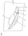
- FIG. 1 shows a movable door outer handle 1 of a motor vehicle with passive entry functions in a perspective view.
- the vehicle user In the case of the passive entry system, the vehicle user carries with him an identification transmitter (ID transmitter), which is activated to transmit an authorization code from the vehicle by radio.
- ID transmitter an identification transmitter
- the unlocking and locking takes place in the normal function without the use of a mechanical key or active operation of a remote key only due to a code release.
- the vehicle user by means of a mechanical emergency key, the vehicle via the lock cylinder 9, which is housed in the lock cylinder tower 10, mechanically unlock to gain access to the vehicle.
- the cylinder tower 5 connects, which consists of the lock cylinder 9 and a cover 13.
- At least two capacitive sensors are arranged. One sits to the recessed handle directed towards the handle part, which serves to detect the presence of a hand in the grip 11. Due to the change in the capacitive field caused by a controller generates a signal that responds directly to the ID transmitter or causes the central control unit to the ID transmitter per Request radio to send the identification code.
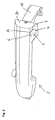
- FIG. 2 an inventive handle part 2 of a door outer handle 1 is shown, which has an additional capacitive sensor 3, to activate the locking of the vehicle.
- the capacitive sensor sits behind the visible operation field 4. Touching this operation field 4 in turn triggers the query of the ID transmitter for the identification code, so as to ensure that only authorized persons can lock the vehicle. If the ID transmitter is in the radio range and the code has been received from the vehicle and evaluated positively, the locking process is carried out.
- the operating field 4 is a recessed trough 15 on the underside 14 of the handle part 2.
- the trough 15 is formed from the handle part 2. Behind this, the capacitive electrode 16 is arranged in the interior region of the grip part 2.
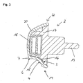
- FIG. 3 is shown in section through the trough 15 and capacitive element 16, the internal structure of the handle part 2.
- the handle part 2 is constructed in two parts and consists of a lower shell 17 with molded actuating finger 19, for actuating the lock and an upper shell 20.
- the lower shell receives the handle electronics 18 in a recess 21, wherein the handle electronics 18 includes, inter alia, further capacitive elements and controllers ,
- the lower shell 17 together with the electronics 18 is covered by the upper shell 20.
- the upper shell 20 also forms the visible side to the vehicle user.
- a trough 15 is formed at the bottom 14 of the upper shell 20, a trough 15 is formed. Behind it sits, received from the lower shell 17, the electrode 16 of the capacitive sensor to activate the locking of the vehicle.
- the electrode 16 is connected by cable to the electronics 18, and a controller.
- a projection 7 made of the material of the upper shell 20 is formed, which is allowed so that the water that would flow from the top 22 to the bottom 14 via the operating field 4 of the capacitive sensor 3, there drips. This effectively prevents false triggering.
- the projection 7 is formed only at the upper edge 23 of the trough 15, but may also be formed circumferentially.
- the drip can be formed as a groove or applied as an additional, possibly design element on the handle part, z.b. through a ring which is glued on.
- the trough 7 together with the capacitive electrode 16 may alternatively be integrated in the cylinder tower 5, or a cylinder tower dummy on the other door handles of the vehicle, which do not contain a lock cylinder.
- the application is not limited to pull handles, but can also be used with folding handles and tailgate actuators.
Landscapes
- Engineering & Computer Science (AREA)
- Mechanical Engineering (AREA)
- Lock And Its Accessories (AREA)
Description
- Die vorliegende Erfindung betrifft einen Aussengriff für eine Tür oder Klappe an einem Kraftfahrzeug, mit einem Griffteil und mindestens einem kapazitiven Aktivierungssensor zur Aktivierung von Entriegelungs- und / oder Verriegelungsvorgängen.
- Aus der
DE 102 40 828 A1 ist ein Zugangsystem für ein Kraftfahrzeug bekannt, das mit einem Türaussengriff ausgestattet ist, in dem Aktivierungsmittel zur Veranlassung der Generierung eines Entriegelungs-Aufforderungsignals und eines Verriegelungsaufforderungssignals angeordnet sind. Bei den Aktivierungsmitteln handelt es sich unter anderem um kapazitive Sensoren. - Bei Annäherung des Fahrzeugnutzers erkennt ein Näherungssensor die Annäherung und startet die Abfrage des Zugangsberechtigungscodes vom ID-Geber, den der Fahrzeugnutzer bei sich trägt. Nach erfolgreicher Übermittlung und Überprüfung des Codes veranlasst eine Steuereinheit des Fahrzeugs die Entriegelung.
- Der Schließvorgang wird durch die Betätigung eines Sensors im Bereich des Türgriffes in ähnlicher Form eingeleitet. Das Auslösen des Sensors löst eine Berechtigungsabfrage aus und sofern der ID-Geber, der sich in der Nähe befinden muss den korrekten Code zurücksendet hat, wird der Verriegelungsvorgang ausgeführt.
- Der Einsatz von kapazitiven Sensoren bei passiven Zugangsystemen von Kraftfahrzeugen hat sich prinzipiell in der Praxis bewährt, es gibt jedoch Probleme in Bezug auf Fehlauslösungen, insbesondere bezüglich des Auslösens des Verriegelungsvorganges.
- Die Fehlauslösungen werden vorrangig durch Wasser verursacht, das am Griff über das Betätigungsfeld des Sensors abläuft. Das Wasser beeinflusst das kapazitive Feld, so dass die Auswertelektronik dies als Kapazitätsänderung feststellt und die Kommunikation mit dem ID-Geber auslöst. Wenn sich der Fahrzeugnutzer nun in der Nähe seines Fahrzeuges aufhält, das kann auch heißen sich ggf. mit dem ID-Geber im Fahrzeug befindet, wird der Verriegelungsvorgang ohne Beabsichtigung eingeleitet. Wasser läuft in der Regel bei Regen oder etwa beim Waschen am Griff herunter.
- Der Erfindung liegt daher die Aufgabe zugrunde ein Aussengriff mit einfachen Mitteln und unter geringen Kosten, so zu gestalten, dass auftropfendes oder ablaufendes Wasser etwaige kapazitive Sensoren des Entriegelungs- und Verriegelungssystems an Fahrzeugen nicht beeinflusst.
- Gelöst wird diese Aufgabe dadurch, dass das Betätigungsfeld mindestens eines Sensors im unteren Bereich des Aussengriffs angeordnet ist, so dass Regen und ablaufendes Wasser kein Auslösung des Sensors verursacht. Der Regen trifft nur auf die oben liegenden und seitlichen Flächen.
- Vorteilhaft an dieser technischen Lösung ist, dass wirksam verhindert wird, dass es zu, für den Fahrzeugnutzer ärgerlichen, Fehlauslösungen kommt und dass diese Maßnahme kostengünstig, gerade in der Massenfertigung, eingesetzt werden kann.
- In einer Ausgestaltung der Erfindung ist das. Betätigungsfeld am Griffteil angeordnet. In einer weiteren Ausgestaltung ist das Betätigungsfeld am Zylinderturm oder der Zylinderturmattrappe angeordnet.
- Die Erfindung sieht in vorteilhafter Weise vor, dass das Betätigungsfeld am Randbereich einen Vorsprung aufweist, der anlaufendes Wasser abtropfen lässt.
- Der Vorsprung kann umlaufend sein oder sich nur über einen Teilbereich des Betätigungsfeldes erstrecken.
- Alternativ kann anstatt eines Vorsprungs eine Nut oder eine Nutbereich zum gleichen Zweck Verwendung finden.
- Das auf den Aussengriff auftreffende Wasser läuft nach unten ab, doch bevor es an der Unterseite entlang fließt und auf die Betätigungsfläche trifft, läuft es über den Vorsprung oder die Nut, die ein Abtropfen vom Aussengriff verursachen.
- Die Erfindung sieht in vorteilhafter Weise vor, dass der Vorsprung oder die Nut im bzw. aus dem Griffteil gebildet sind.
- Alternativ kann vorgesehen sein, dass der Vorsprung durch ein separates anzusetzendes Bauteil gebildet wird.
- Die Erfindung sieht weiterhin in vorteilhafter Weise vor, dass der Aussengriff einen Näherungssensor aufweist.
- In einer weiteren Ausgestaltung der Erfindung ist vorgesehen, dass das kapazitive Sensorelement, im Griffteil oder dem Zylinderturmteil, hinter dem Betätigungsfeld angeordnet ist.
- Im folgenden wird unter Bezugnahme auf die Zeichnungen ein Ausführungsbeispiel der Erfindung erläutert:
- Es zeigen:
- Fig. 1:
- perspektivische Ansicht eines Türaussengriffs eines Fahrzeuges gemäß dem Stand der Technik
- Fig 2.:
- eine perspektivische Ansicht eines Griffteils, an welchen die Erfindung realisiert ist
- Fig. 3. :
- eine Schnitt durch das Griffteil eines erfindungsgemäßen Türaussengriffs
-
Figur 1 zeigt einen beweglichen Türaussengriff 1 eines Kraftfahrzeuges mit Passiv-Entry-Funktionen in perspektivischer Ansicht. - Beim Passiv-Entry-System trägt der Fahrzeugnutzer einen Identifikation-Geber (ID-Geber) bei sich, der zur Übermittlung eines Berechtigungscodes vom Fahrzeug per Funk aktiviert wird. Die Entriegelung und Verriegelung findet in der Normalfunktion ohne die Verwendung eines mechanischen Schlüssels oder aktive Bedienung eines Funkschlüssels nur aufgrund einer Codefreigabe statt.
- Lediglich bei Ausfall des Systems kann der Fahrzeugnutzer mittels eines mechanischen Notschlüssels das Fahrzeug über den Schließzylinder 9 , der im Schließzylinderturm 10 untergebracht ist, mechanisch entriegeln, um Zugang zum Fahrzeug zu erhalten.
- Es handelt sich um einen Ziehgriff, der durch Eingreifen der Hand in die Griffmulde 11, die in das Türblech 12 geformt ist , gegriffen werden kann, um ihn dann nach außen zu ziehen, wodurch das Türschloss, wenn es entriegelt ist, geöffnet wird, d.h. die Drehfalle im Schloss freigegeben wird.
- In der Verlängerung des Türgriffs 1 schließt sich der Zylinderturm 5 an, der aus dem Schließzylinder 9 und einer Abdeckung 13 besteht.
- Im Griffteil 2 sind mindestens zwei kapazitive Sensoren angeordnet. Einer sitzt zur Griffmulde hin gerichtet im Griffteil, der dazu dient die Anwesenheit einer Hand in der Griffmulde 11 zu detektieren. Aufgrund der verursachten Änderung des kapazitiven Feldes wird durch einen Controller ein Signal erzeugt, das den ID-Geber direkt anspricht oder die zentrale Steuereinheit dazu veranlasst den ID-Geber per Funk zur Sendung des Identifikations-Codes aufzufordern.
- Nach Sendung des Identifikations-Codes seitens des ID-Gebers und seiner positiven Auswertung des Codes durch die zentrale Steuereinheit wird die Entriegelung der Türschlösser veranlasst.
- In
Figur 2 ist ein erfindungsgemäßes Griffteil 2 eines Türaussengriffes 1 dargestellt, das einen zusätzlichen kapazitiven Sensor 3, zur Aktivierung der Verriegelung des Fahrzeuges, aufweist. Der kapazitive Sensor sitzt hinter der dem sichtbaren Betätigungsfeld 4. Das Berühren dieses Betätigungsfeldes 4 löst wiederum die Abfrage des ID-Gebers nach dem Identifikation-Code aus, damit sichergestellt ist, dass nur Berechtigte das Fahrzeug verriegeln können. Sofern sich der ID-Geber in der Funkreichweite befindet und der Code vom Fahrzug empfangen und positiv ausgewertet worden ist, wird der Verriegelungsvorgang ausgeführt. - Das Betätigungsfeld 4 ist eine vertiefte Mulde 15 auf der Unterseite 14 des Griffteils 2. Die Mulde 15 wird aus dem Griffteil 2 gebildet. Dahinter ist im Innenbereich des Griffteils 2 die kapazitive Elektrode 16 angeordnet.
- In
Figur 3 ist im Schnitt durch die Mulde 15 und kapazitiven Element 16 der innere Aufbau des Griffteils 2 dargestellt. - Der Griffteil 2 ist zweiteilig aufgebaut und besteht aus einer Unterschale 17 mit angespritztem Betätigungsfinger 19, zur Betätigung des Schlosses und einer Oberschale 20. Die Unterschale nimmt die Griffelektronik 18 in einer Ausnehmung 21 auf, wobei die Griffelektronik 18 unter anderem weitere kapazitive Elemente und Controller beinhaltet.
- Die Unterschale 17 mitsamt der Elektronik 18 wird durch die Oberschale 20 abgedeckt.
- Die Oberschale 20 bildet gleichzeitig die sichtbare Seite zum Fahrzeugnutzer.
- An der Unterseite 14 der Oberschale 20 ist eine Mulde 15 angeformt. Dahinter sitzt, von der Unterschale 17 aufgenommen, die Elektrode 16 des kapazitiven Sensors zur Aktivierung der Verriegelung des Fahrzeuges. Die Elektrode 16 ist mittels Kabel mit der Elektronik 18, bzw. einem Controller verbunden.
- An der Oberseite der Mulde 15 ist ein Vorsprung 7 aus dem Material der Oberschale 20 herausgebildet, der so gestattet ist, dass das Wasser, das von der Oberseite 22 zur Unterseite 14 über das Betätigungsfeld 4 des kapazitiven Sensors 3 fließen würde, dort abtropft. Dadurch werden Fehlauslösungen wirksam verhindert.
- Der Vorsprung 7 ist nur am oberen Rand 23 der Mulde 15 ausgebildet, kann aber auch umlaufend ausgebildet werden.
- Des Weiteren kann das Abtropfelement als Nut ausgebildet sein oder als zusätzliches, ggf. gestalterisches Element auf den Griffteil aufgebracht sein, z.b. durch einen Ring der aufgeklebt wird.
- Die Mulde 7 mitsamt kapazitiver Elektrode 16 kann alternativ im Zylinderturm 5, bzw. einer Zylinderturmattrappe an den übrigen Türgriffen des Fahrzeugs, die keinen Schließzylinder enthalten, integriert sein.
- Es ist genauso möglich weitere kapazitive Sensoren am Aussengriff für weitere Komfortbetätigungen bei gleichem Aufbau zu integrieren, sei es am Griffteil 2, Zylinderturm 5 oder jeweils am Griffteil 2 und Zylinderturm 5.
- Die Anwendung ist nicht auf Ziehgriffe beschränkt, sondern kann auch bei Klappgriffen und Heckklappenbetätigern zum Einsatz kommen.
Claims (12)
- Aussengriff (1) für eine Tür oder Klappe an einem Kraftfahrzeug, mit einem Griffteil (2) und mit mindestens einem kapazitiven Aktivierungssensor (3) zur Aktivierung von Entriegelungs- und/ oder Verriegelungsvorgängen dadurch gekennzeichnet, dass das Betätigungsfeld (4) mindestes eines Sensors (3) im unteren Bereich des Aussengriffs (1) angeordnet ist, so dass Regen und ablaufendes Wasser keine Auslösung des Sensors (3) verursachen.
- Aussengriff nach Anspruch 1, dadurch gekennzeichnet, dass das mindestens eine Betätigungsfeld (4) am Griffteil (2) angeordnet ist.
- Aussengriff nach Anspruch 1, dadurch gekennzeichnet, dass das mindestens eine Betätigungsfeld (4) am Zylinderturm (4) oder der Zylinderturmattrappe angeordnet ist.
- Aussengriff nach einem der Ansprüche von 1 bis 3 dadurch gekennzeichnet, dass das Betätigungsfeld (4) am Randbereich einen Vorsprung (7) aufweist, der anlaufendes Wasser abtropfen lässt.
- Aussengriff nach Anspruch 4 , dadurch gekennzeichnet, dass der Vorsprung (7) um das Betätigungsfeld (4) umlaufend angeordnet ist.
- Aussengriff nach Anspruch 4, dadurch gekennzeichnet , dass der Vorsprung (7) an der Oberseite des Betätigungsfeldes (4) über einen Teilbereich angeordnet ist.
- Aussengriff nach einem der Ansprüche von 4 bis 6 dadurch gekennzeichnet, dass der Vorsprung (7) einteilig aus einem Griffbauteil (8) gebildet wird.
- Aussengriff nach einem der Ansprüche von 4 bis 6 dadurch gekennzeichnet, dass der Vorsprung (7) aus einem separat auf das Griffteil aufgebrachten Teil gebildet wird.
- Aussengriff nach einem der Ansprüche von 1 bis 3 dadurch gekennzeichnet, dass zur Wasserableitung das Betätigungsfeld (4) des Sensors (3) mit einer Nut umgeben ist.
- Aussengriff nach einem der Ansprüche von 1 bis 3 dadurch gekennzeichnet, dass zur Wasserableitung das Betätigungsfeld (4) des Sensors (3) teilweise im oberen Bereich am Umfang mit einer Nut versehen ist.
- Aussengriff nach einem der vorhergehenden Ansprüche dadurch gekennzeichnet, dass der Aussengriff (1) einen Näherungssensor aufweist.
- Aussengriff nach einem der vorhergehenden Ansprüche dadurch gekennzeichnet, dass das kapazitive Sensorelement (3) im Griffteil (2) oder dem Zylinderturmteil (5) hinter dem Betätigungsfeld (4) angeordnet ist.
Applications Claiming Priority (2)
| Application Number | Priority Date | Filing Date | Title |
|---|---|---|---|
| DE102005041551A DE102005041551A1 (de) | 2005-08-31 | 2005-08-31 | Aussengriff für eine Tür oder Klappe an einem Kraftfahrzeug |
| PCT/EP2006/008393 WO2007025689A1 (de) | 2005-08-31 | 2006-08-26 | Aussengriff für eine tür oder klappe an einem kraftfahrzeug |
Publications (2)
| Publication Number | Publication Date |
|---|---|
| EP1926873A1 EP1926873A1 (de) | 2008-06-04 |
| EP1926873B1 true EP1926873B1 (de) | 2009-03-04 |
Family
ID=37654821
Family Applications (1)
| Application Number | Title | Priority Date | Filing Date |
|---|---|---|---|
| EP06791685A Not-in-force EP1926873B1 (de) | 2005-08-31 | 2006-08-26 | Aussengriff für eine tür oder klappe an einem kraftfahrzeug |
Country Status (5)
| Country | Link |
|---|---|
| EP (1) | EP1926873B1 (de) |
| KR (1) | KR101250731B1 (de) |
| AT (1) | ATE424496T1 (de) |
| DE (2) | DE102005041551A1 (de) |
| WO (1) | WO2007025689A1 (de) |
Families Citing this family (26)
| Publication number | Priority date | Publication date | Assignee | Title |
|---|---|---|---|---|
| JP4947348B2 (ja) | 2006-09-13 | 2012-06-06 | アイシン精機株式会社 | 車両用ドアハンドル装置 |
| JP4938580B2 (ja) | 2007-07-27 | 2012-05-23 | アイシン精機株式会社 | ドアハンドル装置 |
| JP4751861B2 (ja) * | 2007-07-27 | 2011-08-17 | アイシン精機株式会社 | ドアハンドル装置 |
| DE102007040775B4 (de) * | 2007-08-29 | 2020-09-10 | Volkswagen Ag | Verfahren und Vorrichtung zum Öffnen eines Schließelements eines Kraftfahrzeugs |
| KR101111938B1 (ko) * | 2007-11-30 | 2012-02-15 | 도요타 지도샤(주) | 정전 용량식 접촉 검지 장치 및 도어 잠금 장치 |
| US9260882B2 (en) | 2009-03-12 | 2016-02-16 | Ford Global Technologies, Llc | Universal global latch system |
| US8690205B2 (en) | 2011-02-21 | 2014-04-08 | Yale Security Inc. | Door lockset |
| US9551166B2 (en) | 2011-11-02 | 2017-01-24 | Ford Global Technologies, Llc | Electronic interior door release system |
| US9957737B2 (en) | 2012-06-29 | 2018-05-01 | Ford Global Technologies, Llc | Flush-mounted door handle for vehicles |
| US9593514B2 (en) | 2013-02-18 | 2017-03-14 | Ford Global Technologies, Llc | Seamless exterior handle for a vehicle door |
| US9903142B2 (en) | 2014-05-13 | 2018-02-27 | Ford Global Technologies, Llc | Vehicle door handle and powered latch system |
| US10119308B2 (en) | 2014-05-13 | 2018-11-06 | Ford Global Technologies, Llc | Powered latch system for vehicle doors and control system therefor |
| US10323442B2 (en) | 2014-05-13 | 2019-06-18 | Ford Global Technologies, Llc | Electronic safe door unlatching operations |
| US10273725B2 (en) | 2014-05-13 | 2019-04-30 | Ford Global Technologies, Llc | Customer coaching method for location of E-latch backup handles |
| US9909344B2 (en) | 2014-08-26 | 2018-03-06 | Ford Global Technologies, Llc | Keyless vehicle door latch system with powered backup unlock feature |
| US9725069B2 (en) | 2015-10-12 | 2017-08-08 | Ford Global Technologies, Llc | Keyless vehicle systems |
| DE102016110345A1 (de) * | 2016-06-03 | 2017-12-07 | Huf Hülsbeck & Fürst Gmbh & Co. Kg | Zusätzliches Türgriffmodul für eine Türgriffeinheit |
| US11028620B2 (en) * | 2016-07-08 | 2021-06-08 | Honda Motor Co., Ltd. | Door structure |
| US10227810B2 (en) | 2016-08-03 | 2019-03-12 | Ford Global Technologies, Llc | Priority driven power side door open/close operations |
| US10087671B2 (en) | 2016-08-04 | 2018-10-02 | Ford Global Technologies, Llc | Powered driven door presenter for vehicle doors |
| US10329823B2 (en) | 2016-08-24 | 2019-06-25 | Ford Global Technologies, Llc | Anti-pinch control system for powered vehicle doors |
| US10458171B2 (en) | 2016-09-19 | 2019-10-29 | Ford Global Technologies, Llc | Anti-pinch logic for door opening actuator |
| US10604970B2 (en) | 2017-05-04 | 2020-03-31 | Ford Global Technologies, Llc | Method to detect end-of-life in latches |
| JP6907797B2 (ja) * | 2017-08-09 | 2021-07-21 | トヨタ自動車株式会社 | 車両用ドア開閉制御装置 |
| US10907386B2 (en) | 2018-06-07 | 2021-02-02 | Ford Global Technologies, Llc | Side door pushbutton releases |
| CN113459995B (zh) * | 2021-06-28 | 2022-03-25 | 东风汽车集团股份有限公司 | 一种强制上电启动车辆的控制方法 |
Family Cites Families (6)
| Publication number | Priority date | Publication date | Assignee | Title |
|---|---|---|---|---|
| DE29802678U1 (de) * | 1998-02-17 | 1998-05-14 | Degler, Reinhard, 33039 Nieheim | Alarmanlage für Fahrzeuge |
| FR2828225B1 (fr) * | 2001-08-01 | 2003-10-31 | Valeo Electronique | Poignee d'ouvrant pour vehicule automobile |
| DE10212794A1 (de) * | 2001-12-12 | 2003-06-26 | Witte Velbert Gmbh & Co Kg | Elektrische Komponente beinhaltendes Kunststoffspitzgussteil, insbesondere Kraftfahrzeugtürgriff |
| EP1476623B1 (de) * | 2002-02-22 | 2006-11-22 | Schaffner Emv Ag | Elektronische steuerschaltung mit einem berührungssensor für ein fahrzeugtür-schliesssystem |
| DE10240828A1 (de) * | 2002-09-04 | 2004-03-18 | Robert Bosch Gmbh | Zugangssystem für ein Fahrzeug |
| DE10300573A1 (de) * | 2003-01-10 | 2004-07-22 | Daimlerchrysler Ag | Vorrichtung zum Ver-und Entriegeln einer Fahrzeugtür |
-
2005
- 2005-08-31 DE DE102005041551A patent/DE102005041551A1/de not_active Withdrawn
-
2006
- 2006-08-26 AT AT06791685T patent/ATE424496T1/de not_active IP Right Cessation
- 2006-08-26 DE DE502006003028T patent/DE502006003028D1/de active Active
- 2006-08-26 KR KR1020087007500A patent/KR101250731B1/ko not_active Expired - Fee Related
- 2006-08-26 WO PCT/EP2006/008393 patent/WO2007025689A1/de not_active Ceased
- 2006-08-26 EP EP06791685A patent/EP1926873B1/de not_active Not-in-force
Also Published As
| Publication number | Publication date |
|---|---|
| WO2007025689A1 (de) | 2007-03-08 |
| KR101250731B1 (ko) | 2013-04-03 |
| DE502006003028D1 (de) | 2009-04-16 |
| KR20080040790A (ko) | 2008-05-08 |
| EP1926873A1 (de) | 2008-06-04 |
| ATE424496T1 (de) | 2009-03-15 |
| DE102005041551A1 (de) | 2007-03-01 |
Similar Documents
| Publication | Publication Date | Title |
|---|---|---|
| EP1926873A1 (de) | Aussengriff für eine tür oder klappe an einem kraftfahrzeug | |
| EP1512814B1 (de) | Kraftfahrzeug-Türschliesssystem und Türgriff | |
| EP2528785B1 (de) | Steuervorrichtung für ein fahrzeug mit automatisch öffnender und/oder automatisch schliessender klappe | |
| EP2567049B1 (de) | Bedienverfahren und bedienvorrichtung für ein fahrzeug | |
| EP2728093B1 (de) | Sicherheitssystem mit einem Unfallerkennungssensor | |
| EP2535489B1 (de) | Handhabe eines beweglichen Teils mit einer Elektronikbaugruppe, die an unterschiedlichen Bauteilen angeordnet ist | |
| EP2875201B1 (de) | Handhabe mit zwei elektroden | |
| DE102012108004A1 (de) | Sicherheitssystem für eine Kraftfahrzeugtür eines Kraftfahrzeuges mit mindestens zwei Sensoren | |
| WO2007003534A1 (de) | Griffvorrichtung | |
| EP2831356A2 (de) | Kraftfahrzeugtürverschluss | |
| EP2592201A2 (de) | Handhabe | |
| DE102012107189A1 (de) | Elektronikmodul für eine Handhabe | |
| DE102016124275A1 (de) | Verfahren zur Ansteuerung einer motorischen Verschlusselementanordnung eines Kraftfahrzeugs | |
| EP1581710A1 (de) | Vorrichtung zum ver- und entriegeln einer fahrzeugtür | |
| EP1584777B1 (de) | Schliesssystem für ein Fahrzeug und Verfahren zu dessen Betrieb | |
| WO2007028488A1 (de) | Kraftfahrzeug mit automatisch öffnender klappe | |
| DE102009034549A1 (de) | Moduleinheit | |
| DE102008062627A1 (de) | System und Verfahren für die entfernte Aktivierung unter Verwendung einer Sender-Schalteranordnung | |
| DE102007040775B4 (de) | Verfahren und Vorrichtung zum Öffnen eines Schließelements eines Kraftfahrzeugs | |
| DE102004046903A1 (de) | Vorrichtung zur Auslösung eines Abfragesignals | |
| DE102015114014A1 (de) | Gesicherte Betätigungsvorrichtung | |
| DE29921946U1 (de) | Schaltvorrichtung für einen Diebstahlsicherungsantrieb eines Kraftfahrzeugtürverschlusses | |
| EP1989084B1 (de) | Handhabe | |
| DE102013021613B4 (de) | Kraftfahrzeug | |
| DE10262353B4 (de) | Schlüssellose Sicherheits-/Betätigungseinrichtung für Kraftfahrzeuge |
Legal Events
| Date | Code | Title | Description |
|---|---|---|---|
| PUAI | Public reference made under article 153(3) epc to a published international application that has entered the european phase |
Free format text: ORIGINAL CODE: 0009012 |
|
| 17P | Request for examination filed |
Effective date: 20080326 |
|
| AK | Designated contracting states |
Kind code of ref document: A1 Designated state(s): AT BE BG CH CY CZ DE DK EE ES FI FR GB GR HU IE IS IT LI LT LU LV MC NL PL PT RO SE SI SK TR |
|
| GRAP | Despatch of communication of intention to grant a patent |
Free format text: ORIGINAL CODE: EPIDOSNIGR1 |
|
| GRAS | Grant fee paid |
Free format text: ORIGINAL CODE: EPIDOSNIGR3 |
|
| DAX | Request for extension of the european patent (deleted) | ||
| GRAA | (expected) grant |
Free format text: ORIGINAL CODE: 0009210 |
|
| AK | Designated contracting states |
Kind code of ref document: B1 Designated state(s): AT BE BG CH CY CZ DE DK EE ES FI FR GB GR HU IE IS IT LI LT LU LV MC NL PL PT RO SE SI SK TR |
|
| REG | Reference to a national code |
Ref country code: GB Ref legal event code: FG4D Free format text: NOT ENGLISH |
|
| REG | Reference to a national code |
Ref country code: CH Ref legal event code: EP |
|
| REG | Reference to a national code |
Ref country code: IE Ref legal event code: FG4D Free format text: LANGUAGE OF EP DOCUMENT: GERMAN |
|
| REF | Corresponds to: |
Ref document number: 502006003028 Country of ref document: DE Date of ref document: 20090416 Kind code of ref document: P |
|
| PG25 | Lapsed in a contracting state [announced via postgrant information from national office to epo] |
Ref country code: SI Free format text: LAPSE BECAUSE OF FAILURE TO SUBMIT A TRANSLATION OF THE DESCRIPTION OR TO PAY THE FEE WITHIN THE PRESCRIBED TIME-LIMIT Effective date: 20090304 Ref country code: NL Free format text: LAPSE BECAUSE OF FAILURE TO SUBMIT A TRANSLATION OF THE DESCRIPTION OR TO PAY THE FEE WITHIN THE PRESCRIBED TIME-LIMIT Effective date: 20090304 Ref country code: LT Free format text: LAPSE BECAUSE OF FAILURE TO SUBMIT A TRANSLATION OF THE DESCRIPTION OR TO PAY THE FEE WITHIN THE PRESCRIBED TIME-LIMIT Effective date: 20090304 Ref country code: FI Free format text: LAPSE BECAUSE OF FAILURE TO SUBMIT A TRANSLATION OF THE DESCRIPTION OR TO PAY THE FEE WITHIN THE PRESCRIBED TIME-LIMIT Effective date: 20090304 |
|
| NLV1 | Nl: lapsed or annulled due to failure to fulfill the requirements of art. 29p and 29m of the patents act | ||
| PG25 | Lapsed in a contracting state [announced via postgrant information from national office to epo] |
Ref country code: LV Free format text: LAPSE BECAUSE OF FAILURE TO SUBMIT A TRANSLATION OF THE DESCRIPTION OR TO PAY THE FEE WITHIN THE PRESCRIBED TIME-LIMIT Effective date: 20090304 Ref country code: PL Free format text: LAPSE BECAUSE OF FAILURE TO SUBMIT A TRANSLATION OF THE DESCRIPTION OR TO PAY THE FEE WITHIN THE PRESCRIBED TIME-LIMIT Effective date: 20090304 Ref country code: SE Free format text: LAPSE BECAUSE OF FAILURE TO SUBMIT A TRANSLATION OF THE DESCRIPTION OR TO PAY THE FEE WITHIN THE PRESCRIBED TIME-LIMIT Effective date: 20090604 |
|
| REG | Reference to a national code |
Ref country code: IE Ref legal event code: FD4D |
|
| PG25 | Lapsed in a contracting state [announced via postgrant information from national office to epo] |
Ref country code: EE Free format text: LAPSE BECAUSE OF FAILURE TO SUBMIT A TRANSLATION OF THE DESCRIPTION OR TO PAY THE FEE WITHIN THE PRESCRIBED TIME-LIMIT Effective date: 20090304 Ref country code: ES Free format text: LAPSE BECAUSE OF FAILURE TO SUBMIT A TRANSLATION OF THE DESCRIPTION OR TO PAY THE FEE WITHIN THE PRESCRIBED TIME-LIMIT Effective date: 20090615 Ref country code: IE Free format text: LAPSE BECAUSE OF FAILURE TO SUBMIT A TRANSLATION OF THE DESCRIPTION OR TO PAY THE FEE WITHIN THE PRESCRIBED TIME-LIMIT Effective date: 20090304 Ref country code: CZ Free format text: LAPSE BECAUSE OF FAILURE TO SUBMIT A TRANSLATION OF THE DESCRIPTION OR TO PAY THE FEE WITHIN THE PRESCRIBED TIME-LIMIT Effective date: 20090304 Ref country code: PT Free format text: LAPSE BECAUSE OF FAILURE TO SUBMIT A TRANSLATION OF THE DESCRIPTION OR TO PAY THE FEE WITHIN THE PRESCRIBED TIME-LIMIT Effective date: 20090818 |
|
| PG25 | Lapsed in a contracting state [announced via postgrant information from national office to epo] |
Ref country code: RO Free format text: LAPSE BECAUSE OF FAILURE TO SUBMIT A TRANSLATION OF THE DESCRIPTION OR TO PAY THE FEE WITHIN THE PRESCRIBED TIME-LIMIT Effective date: 20090304 Ref country code: IS Free format text: LAPSE BECAUSE OF FAILURE TO SUBMIT A TRANSLATION OF THE DESCRIPTION OR TO PAY THE FEE WITHIN THE PRESCRIBED TIME-LIMIT Effective date: 20090704 Ref country code: SK Free format text: LAPSE BECAUSE OF FAILURE TO SUBMIT A TRANSLATION OF THE DESCRIPTION OR TO PAY THE FEE WITHIN THE PRESCRIBED TIME-LIMIT Effective date: 20090304 |
|
| PLBE | No opposition filed within time limit |
Free format text: ORIGINAL CODE: 0009261 |
|
| STAA | Information on the status of an ep patent application or granted ep patent |
Free format text: STATUS: NO OPPOSITION FILED WITHIN TIME LIMIT |
|
| PG25 | Lapsed in a contracting state [announced via postgrant information from national office to epo] |
Ref country code: BG Free format text: LAPSE BECAUSE OF FAILURE TO SUBMIT A TRANSLATION OF THE DESCRIPTION OR TO PAY THE FEE WITHIN THE PRESCRIBED TIME-LIMIT Effective date: 20090604 Ref country code: DK Free format text: LAPSE BECAUSE OF FAILURE TO SUBMIT A TRANSLATION OF THE DESCRIPTION OR TO PAY THE FEE WITHIN THE PRESCRIBED TIME-LIMIT Effective date: 20090304 |
|
| 26N | No opposition filed |
Effective date: 20091207 |
|
| BERE | Be: lapsed |
Owner name: HUF HULSBECK & FURST G.M.B.H. & CO. KG Effective date: 20090831 |
|
| PG25 | Lapsed in a contracting state [announced via postgrant information from national office to epo] |
Ref country code: MC Free format text: LAPSE BECAUSE OF NON-PAYMENT OF DUE FEES Effective date: 20090831 |
|
| REG | Reference to a national code |
Ref country code: FR Ref legal event code: ST Effective date: 20100430 |
|
| PG25 | Lapsed in a contracting state [announced via postgrant information from national office to epo] |
Ref country code: BE Free format text: LAPSE BECAUSE OF NON-PAYMENT OF DUE FEES Effective date: 20090831 |
|
| PG25 | Lapsed in a contracting state [announced via postgrant information from national office to epo] |
Ref country code: FR Free format text: LAPSE BECAUSE OF NON-PAYMENT OF DUE FEES Effective date: 20090831 |
|
| PG25 | Lapsed in a contracting state [announced via postgrant information from national office to epo] |
Ref country code: GR Free format text: LAPSE BECAUSE OF FAILURE TO SUBMIT A TRANSLATION OF THE DESCRIPTION OR TO PAY THE FEE WITHIN THE PRESCRIBED TIME-LIMIT Effective date: 20090605 |
|
| PG25 | Lapsed in a contracting state [announced via postgrant information from national office to epo] |
Ref country code: AT Free format text: LAPSE BECAUSE OF NON-PAYMENT OF DUE FEES Effective date: 20090826 |
|
| PG25 | Lapsed in a contracting state [announced via postgrant information from national office to epo] |
Ref country code: IT Free format text: LAPSE BECAUSE OF FAILURE TO SUBMIT A TRANSLATION OF THE DESCRIPTION OR TO PAY THE FEE WITHIN THE PRESCRIBED TIME-LIMIT Effective date: 20090304 |
|
| REG | Reference to a national code |
Ref country code: CH Ref legal event code: PL |
|
| GBPC | Gb: european patent ceased through non-payment of renewal fee |
Effective date: 20100826 |
|
| PG25 | Lapsed in a contracting state [announced via postgrant information from national office to epo] |
Ref country code: LU Free format text: LAPSE BECAUSE OF NON-PAYMENT OF DUE FEES Effective date: 20090826 Ref country code: LI Free format text: LAPSE BECAUSE OF NON-PAYMENT OF DUE FEES Effective date: 20100831 Ref country code: CH Free format text: LAPSE BECAUSE OF NON-PAYMENT OF DUE FEES Effective date: 20100831 |
|
| PG25 | Lapsed in a contracting state [announced via postgrant information from national office to epo] |
Ref country code: HU Free format text: LAPSE BECAUSE OF FAILURE TO SUBMIT A TRANSLATION OF THE DESCRIPTION OR TO PAY THE FEE WITHIN THE PRESCRIBED TIME-LIMIT Effective date: 20090905 |
|
| PG25 | Lapsed in a contracting state [announced via postgrant information from national office to epo] |
Ref country code: TR Free format text: LAPSE BECAUSE OF FAILURE TO SUBMIT A TRANSLATION OF THE DESCRIPTION OR TO PAY THE FEE WITHIN THE PRESCRIBED TIME-LIMIT Effective date: 20090304 Ref country code: GB Free format text: LAPSE BECAUSE OF NON-PAYMENT OF DUE FEES Effective date: 20100826 |
|
| PG25 | Lapsed in a contracting state [announced via postgrant information from national office to epo] |
Ref country code: CY Free format text: LAPSE BECAUSE OF FAILURE TO SUBMIT A TRANSLATION OF THE DESCRIPTION OR TO PAY THE FEE WITHIN THE PRESCRIBED TIME-LIMIT Effective date: 20090304 |
|
| PGFP | Annual fee paid to national office [announced via postgrant information from national office to epo] |
Ref country code: DE Payment date: 20200824 Year of fee payment: 15 |
|
| REG | Reference to a national code |
Ref country code: DE Ref legal event code: R119 Ref document number: 502006003028 Country of ref document: DE |
|
| PG25 | Lapsed in a contracting state [announced via postgrant information from national office to epo] |
Ref country code: DE Free format text: LAPSE BECAUSE OF NON-PAYMENT OF DUE FEES Effective date: 20220301 |