EP1927372A1 - Einwegspritze mit eingebauter Karpulle - Google Patents
Einwegspritze mit eingebauter Karpulle Download PDFInfo
- Publication number
- EP1927372A1 EP1927372A1 EP06256102A EP06256102A EP1927372A1 EP 1927372 A1 EP1927372 A1 EP 1927372A1 EP 06256102 A EP06256102 A EP 06256102A EP 06256102 A EP06256102 A EP 06256102A EP 1927372 A1 EP1927372 A1 EP 1927372A1
- Authority
- EP
- European Patent Office
- Prior art keywords
- carpule
- disposable syringe
- built
- barrel
- tubular
- Prior art date
- Legal status (The legal status is an assumption and is not a legal conclusion. Google has not performed a legal analysis and makes no representation as to the accuracy of the status listed.)
- Granted
Links
Images









Classifications
-
- A—HUMAN NECESSITIES
- A61—MEDICAL OR VETERINARY SCIENCE; HYGIENE
- A61M—DEVICES FOR INTRODUCING MEDIA INTO, OR ONTO, THE BODY; DEVICES FOR TRANSDUCING BODY MEDIA OR FOR TAKING MEDIA FROM THE BODY; DEVICES FOR PRODUCING OR ENDING SLEEP OR STUPOR
- A61M5/00—Devices for bringing media into the body in a subcutaneous, intra-vascular or intramuscular way; Accessories therefor, e.g. filling or cleaning devices, arm-rests
- A61M5/178—Syringes
- A61M5/31—Details
- A61M5/32—Needles; Details of needles pertaining to their connection with syringe or hub; Accessories for bringing the needle into, or holding the needle on, the body; Devices for protection of needles
- A61M5/3205—Apparatus for removing or disposing of used needles or syringes, e.g. containers; Means for protection against accidental injuries from used needles
- A61M5/321—Means for protection against accidental injuries by used needles
- A61M5/322—Retractable needles, i.e. disconnected from and withdrawn into the syringe barrel by the piston
- A61M5/3234—Fully automatic needle retraction, i.e. in which triggering of the needle does not require a deliberate action by the user
-
- A—HUMAN NECESSITIES
- A61—MEDICAL OR VETERINARY SCIENCE; HYGIENE
- A61M—DEVICES FOR INTRODUCING MEDIA INTO, OR ONTO, THE BODY; DEVICES FOR TRANSDUCING BODY MEDIA OR FOR TAKING MEDIA FROM THE BODY; DEVICES FOR PRODUCING OR ENDING SLEEP OR STUPOR
- A61M5/00—Devices for bringing media into the body in a subcutaneous, intra-vascular or intramuscular way; Accessories therefor, e.g. filling or cleaning devices, arm-rests
- A61M5/178—Syringes
- A61M5/31—Details
- A61M5/315—Pistons; Piston-rods; Guiding, blocking or restricting the movement of the rod or piston; Appliances on the rod for facilitating dosing ; Dosing mechanisms
- A61M5/31511—Piston or piston-rod constructions, e.g. connection of piston with piston-rod
- A61M2005/31518—Piston or piston-rod constructions, e.g. connection of piston with piston-rod designed to reduce the overall size of an injection device, e.g. using flexible or pivotally connected chain-like rod members
-
- A—HUMAN NECESSITIES
- A61—MEDICAL OR VETERINARY SCIENCE; HYGIENE
- A61M—DEVICES FOR INTRODUCING MEDIA INTO, OR ONTO, THE BODY; DEVICES FOR TRANSDUCING BODY MEDIA OR FOR TAKING MEDIA FROM THE BODY; DEVICES FOR PRODUCING OR ENDING SLEEP OR STUPOR
- A61M5/00—Devices for bringing media into the body in a subcutaneous, intra-vascular or intramuscular way; Accessories therefor, e.g. filling or cleaning devices, arm-rests
- A61M5/178—Syringes
- A61M5/31—Details
- A61M5/32—Needles; Details of needles pertaining to their connection with syringe or hub; Accessories for bringing the needle into, or holding the needle on, the body; Devices for protection of needles
- A61M5/3205—Apparatus for removing or disposing of used needles or syringes, e.g. containers; Means for protection against accidental injuries from used needles
- A61M5/321—Means for protection against accidental injuries by used needles
- A61M5/322—Retractable needles, i.e. disconnected from and withdrawn into the syringe barrel by the piston
- A61M5/3234—Fully automatic needle retraction, i.e. in which triggering of the needle does not require a deliberate action by the user
- A61M2005/3239—Fully automatic needle retraction, i.e. in which triggering of the needle does not require a deliberate action by the user triggered by dislodgement of outer part anchoring the needle portion to the inside of the syringe barrel wall, e.g. a ring-shaped portion
-
- A—HUMAN NECESSITIES
- A61—MEDICAL OR VETERINARY SCIENCE; HYGIENE
- A61M—DEVICES FOR INTRODUCING MEDIA INTO, OR ONTO, THE BODY; DEVICES FOR TRANSDUCING BODY MEDIA OR FOR TAKING MEDIA FROM THE BODY; DEVICES FOR PRODUCING OR ENDING SLEEP OR STUPOR
- A61M5/00—Devices for bringing media into the body in a subcutaneous, intra-vascular or intramuscular way; Accessories therefor, e.g. filling or cleaning devices, arm-rests
- A61M5/002—Packages specially adapted therefor, e.g. for syringes or needles, kits for diabetics
-
- A—HUMAN NECESSITIES
- A61—MEDICAL OR VETERINARY SCIENCE; HYGIENE
- A61M—DEVICES FOR INTRODUCING MEDIA INTO, OR ONTO, THE BODY; DEVICES FOR TRANSDUCING BODY MEDIA OR FOR TAKING MEDIA FROM THE BODY; DEVICES FOR PRODUCING OR ENDING SLEEP OR STUPOR
- A61M5/00—Devices for bringing media into the body in a subcutaneous, intra-vascular or intramuscular way; Accessories therefor, e.g. filling or cleaning devices, arm-rests
- A61M5/178—Syringes
- A61M5/24—Ampoule syringes, i.e. syringes with needle for use in combination with replaceable ampoules or carpules, e.g. automatic
-
- A—HUMAN NECESSITIES
- A61—MEDICAL OR VETERINARY SCIENCE; HYGIENE
- A61M—DEVICES FOR INTRODUCING MEDIA INTO, OR ONTO, THE BODY; DEVICES FOR TRANSDUCING BODY MEDIA OR FOR TAKING MEDIA FROM THE BODY; DEVICES FOR PRODUCING OR ENDING SLEEP OR STUPOR
- A61M5/00—Devices for bringing media into the body in a subcutaneous, intra-vascular or intramuscular way; Accessories therefor, e.g. filling or cleaning devices, arm-rests
- A61M5/178—Syringes
- A61M5/24—Ampoule syringes, i.e. syringes with needle for use in combination with replaceable ampoules or carpules, e.g. automatic
- A61M5/2455—Ampoule syringes, i.e. syringes with needle for use in combination with replaceable ampoules or carpules, e.g. automatic with sealing means to be broken or opened
- A61M5/2466—Ampoule syringes, i.e. syringes with needle for use in combination with replaceable ampoules or carpules, e.g. automatic with sealing means to be broken or opened by piercing without internal pressure increase
-
- A—HUMAN NECESSITIES
- A61—MEDICAL OR VETERINARY SCIENCE; HYGIENE
- A61M—DEVICES FOR INTRODUCING MEDIA INTO, OR ONTO, THE BODY; DEVICES FOR TRANSDUCING BODY MEDIA OR FOR TAKING MEDIA FROM THE BODY; DEVICES FOR PRODUCING OR ENDING SLEEP OR STUPOR
- A61M5/00—Devices for bringing media into the body in a subcutaneous, intra-vascular or intramuscular way; Accessories therefor, e.g. filling or cleaning devices, arm-rests
- A61M5/178—Syringes
- A61M5/31—Details
- A61M5/32—Needles; Details of needles pertaining to their connection with syringe or hub; Accessories for bringing the needle into, or holding the needle on, the body; Devices for protection of needles
- A61M5/3202—Devices for protection of the needle before use, e.g. caps
-
- A—HUMAN NECESSITIES
- A61—MEDICAL OR VETERINARY SCIENCE; HYGIENE
- A61M—DEVICES FOR INTRODUCING MEDIA INTO, OR ONTO, THE BODY; DEVICES FOR TRANSDUCING BODY MEDIA OR FOR TAKING MEDIA FROM THE BODY; DEVICES FOR PRODUCING OR ENDING SLEEP OR STUPOR
- A61M5/00—Devices for bringing media into the body in a subcutaneous, intra-vascular or intramuscular way; Accessories therefor, e.g. filling or cleaning devices, arm-rests
- A61M5/50—Devices for bringing media into the body in a subcutaneous, intra-vascular or intramuscular way; Accessories therefor, e.g. filling or cleaning devices, arm-rests having means for preventing re-use, or for indicating if defective, used, tampered with or unsterile
- A61M5/5013—Means for blocking the piston or the fluid passageway to prevent illegal refilling of a syringe
- A61M5/502—Means for blocking the piston or the fluid passageway to prevent illegal refilling of a syringe for blocking the piston
Definitions
- This invention relates to a disposable syringe, more particularly to a disposable syringe with a carpule.
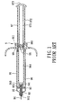
- a pre-filled syringe 9 which includes a barrel 91 having an open widened rear end 911 to receive an operating end 973 of a plunger 97, a needle holder 93 for holding a double-ended needle 94, a push ring 92 for holding the needle holder 93 in the barrel 91, a biasing member 95 disposed between a front end 912 of the barrel 91 and the needle holder 93, and a carpule 96 positioned in the barrel 91 from the rear end 911.
- the carpule 96 has a front seal 963 disposed to seal a front end 962 thereof, and a slidable piston seal including an outer rim member 99 and a releasable core member 98 to seal a rear end 961 of the carpule 96 so as to define a sealed medicament chamber 964.
- the plunger 97 has inner and outer walls 971,972 parallel to and spaced apart from each other and connected at the operating end 973.
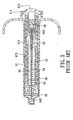
- the rear end 961 of the carpule 96 is associated with the front of the plunger 97. Then the plunger and carpule assembly is introduced into the barrel 91 from the rear end 911, and the carpule 96 is moved forwardly until the front seal 963 is punctured by a communicating end 941 of the needle 94, as shown in Fig. 1 . As a tip end 942 of the needle 94 is inserted into a patient, the plunger 97 is pressed forwardly to inject the contents of the chamber 964 through the needle 94, as shown in Fig. 2 .
- the plunger 97 is further pressed to move the carpule 96 forwardly to remove the push ring 92, thereby freeing the needle holder 93 for retraction of the needle holder 93, the needle 94, the front seal 963 and the core member 98 into the carpule 96 by virtue of a biasing action of the biasing member 95, as shown in Fig. 3 .
- the object of the present invention is to provide a disposable syringe with a built-in carpule which ensures retraction of a used needle into a syringe barrel for safe disposal, which has a carpule that can be pre-assembled in the barrel before injection so that the injection operation is simplified and convenient to conduct, and which can be conveniently rendered unreusable after inject ion in a single operation.
- the disposable syringe with a built-in carpule includes a barrel including front and rear barrel ends opposite to each other along an axis in an axial direction, a surrounding barrel wall which interconnects the front and rear barrel ends, and which includes front and rear wall portions that are disposed proximate to the front and rear barrel ends, respectively, and that define front and rear compartments, respectively.
- a needle cannula has a tip end which is disposed forwardly of the front barrel end in a position of use, and a communicating end which is opposite to the tip end along the axis.
- a seat member has a surrounding gripped portion surrounding the axis.
- a grip member is detachably retained on the rear wall portion, and is configured to be frictionally engaged with the gripped portion to provide a resisting force that guards the gripped portion against movement relative to the rear wall portion in ,the axial direction during a piercing action of the needle cannula for injection, and that permits disengagement of the grip member from the gripped portion so as to enable a subsequent movement of the seat member when the grip member is subj ected to a pressing force.
- a carpule has a tubular wall which is configured to be fit in the rear compartment, and which extends towards the grip member to terminate at a tubular edge surface, and front and rear seal members which are spaced apart from each other in the axial direction, and which, in cooperation with the tubular wall, form a sealed chamber for holding liquid medicament.
- the rear seal member is disposed to be movable to abut against the front seal member in an initial course so as to expel the liquidmedicament out of the sealed chamber, thereby placing the carpule in a used-up position.
- the front seal member has a mating surface which is configured to permit the communicating end to be retained with and to pass through the mating surface such that the needle cannula is in fluid communication with the sealed chamber, and such that once the rear seal member abuts against the front seal member in the used-up position, the pressing force is transmitted through the tubular wall to force the tubular edge surface against the grip member in a subsequent course so as to effect disengagement of the grip member from the gripped portion, thereby placing the seat member in a disengaging position, where the mating surface is closer to the front barrel end than when the carpule is in the used-up position.
- a plunger has a push end which is disposed to move the rear seal member forwardly along the tubular wall to bring the carpule to the used-up position, and to move the mating surface forwardly from the used-up position so as to permit the seat member to be placed in the disengaging position, and an operating end which is opposite to the push end in the axial direction, and which is disposed to extend outwardly of the rear barrel end to be subjected to an external force which is greater in the subsequent course than in the initial course.
- a biasing member is disposed in the front compartment such that, once the seat member is in the disengaging position, the biasing member biases the seat member together with the carpule towards the rear barrel end to retract the tip end of the needle cannula into the barrel, thereby placing the needle cannula in a disposal position.
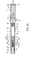
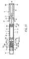
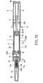
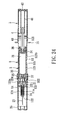
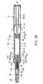
- the first preferred embodiment of a disposable syringe according to the present invention is shown to comprise a barrel 1, a needle cannula 23, a seat member 22, a grip member 21, a biasing member 24, a tip protector 25, a carpule 3, a plunger 4, and a plunger protector 5.
- the barrel 1 includes front and rear barrel ends 122, 121 opposite to each other along an axis in an axial direction, a surrounding barrel wall 12 which interconnects the front and rear barrel ends 122, 121, and which includes front and rear wall portions 124, 123 that are disposed proximate to the front and rear barrel ends 122,121 respectively, and that define front and rear compartments (11a,11b), respectively, and a finger flange 15 which is disposed proximate to the rear barrel end 121.
- the rear compartment (11b) is larger than the front compartment (11a) in diameter so as to form a front annular shoulder 125 therebetween.
- the shoulder 125 has a plurality of fins 14 which extend towards the axis to terminate at an inner peripheral edge 141 that surrounds the axis. Moreover, a recess-like retaining portion 126 is disposed in the rear compartment (11b) adjacent to the rear barrel end 121. An annular stopper 127 is disposed forwardly of the retaining portion 126. A retaining ring 128 is disposed on the rear wall portion 123 adjacent to the front wall portion 124.
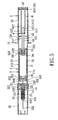
- the needle cannula 23 has a tip end 232 which is disposed forwardly of the front barrel end 122 in a position of use (as shown in Fig. 5 ), and a communicating end 231 which is opposite to the tip end 232 along the axis and which is pointed.
- the seat member 22 has a rear seat end surface 225 which holds the needle cannula 23, which permits rearward extension of the communicating end 231 of the needle cannula 23 therethrough, and which confronts rearwardly, a surrounding gripped portion 222 which surrounds the axis, and a surrounding front abutment surface 223 which is opposite to the rear seat end surface 225 and which confronts forwardly.
- the seat member 22 further has a tubular mount 226 which extends from the surrounding front abutment surface 223 into the front compartment (11a), and which is spaced apart from the inner peripheral edge 141 in radial directions by an inserted clearance that receives a lower end 242 of the biasing member 24 so as to permit the biasing member 24 to abut against the surrounding front abutment surface 223.
- the biasing member 24 is disposed in the front compartment (11a), and has an upper end 241 abutting against the front barrel end 122.
- the seat member 22 further has an annular stepped surface 227 which is spaced apart from the fins 14 of the shoulder 125 in the axial direction, and which extends radially and outwardly to join the gripped portion 222, and a plurality of fin spacers 221 which are angularly displaced from one another about the axis, and each of which is interposed between the annular stepped surface 227 and the fins 14 so as to brace the annular stepped surface 227 against the shoulder 125.
- the grip member 21 is detachably retained on the rear wall portion 123 by a retaining ring 128, and is configured to be frictionally engaged with the gripped portion 222 so as to provide a resisting force that guards the gripped portion 222 against movement relative to the rear wall portion 123 in the axial direction during a piercing action of the needle cannula 23 for injection, and that permits disengagement of the grip member 21 from the gripped portion 222 so as to enable a subsequent movement of the seat member 22 when the grip member 21 is subjected to a pressing force.
- the tip protector 25 is removably sleeved on the barrel wall 12 for shielding the needle cannula 23 in the position of use.
- the carpule 3 has a tubular wall 32 which is configured to be fitted in the rear compartment (11b), and which extends in the axial direction to terminate at a tubular edge surface 322 and a rear wall end 321.
- the carpule 3 further has front and rear seal members 35, 34 which are spaced apart from each other in the axial direction, and which, in cooperation with the tubular wall 32, form a sealed chamber 31 for holding liquid medicament.
- the front seal member 35 is secured to the tubular wall 32 by means of inter-engagement of female and male engaging portions 352,324.
- the rear seal member 34 is limited to the tubular wall 32 by means of inter-engagement of female and male engaging portions 341,323 so as to guard against undesired movement of the rear seal member 34 before injection, and is forced forwardly to permit disengagement of the female engaging portion 341 from the male engaging portion 323 to be moved to abut against the front seal member 35 in an initial course so as to expel the liquid medicament out of the sealed chamber 31, thereby placing the carpule 3 in a used-up position, as shown in Fig. 8 .
- the front seal member 35 has a mating surface 354 which is configured to have a cavity 351 that extends inwardly and towards the sealed chamber 31.
- the pointed communicating end 231 of the needle cannula 23 can pierce the mating surface 354 of the front seal member 35 to be retained in and to pass through the mating surface 354 such that the needle cannula 23 is in fluid communication with the sealed chamber 31, as shown in Fig. 7 .
- the tubular wall 32 of the carpule 3 has a rear annular shoulder 33 which extends radially and inwardly from the rear wall end 321 to guard against a rearward movement of the rear seal member 34 relative to the tubular wall 32.
- the pressing force is transmitted through the tubular wall 32 to force the tubular edge surface 322 against the grip member 21 in a subsequent course so as to effect disengagement of the grip member 21 from the gripped portion 222, thereby placing the seat member 22 in a disengaging position, as shown in Fig. 9 , where the mating surface 354 is closer to the front barrel end 122 than when the carpule 3 is in the used-up position.
- the gripped portion 222 is received in the cavity 351 to ensure that the carpule 3 is kept together with the seat member 22.
- the plunger 4 includes first and second plunger bodies 43,41.
- the first plunger body 43 has a push end 432 which is connected to the rear seal member 34 by virtue of a frictional force, and a first rear end portion 433 opposite to the push end 432 in the axial direction.
- the second plunger body 41 includes an operating end 42 which is disposed to extend outwardly of the rear barrel end 121 to be subjected to an external force (i.e., a pressing force applied by a user) that is greater in a subsequent course (i.e., a needle retraction stroke) than in an initial course (i.e., an injection stroke), and a second front end portion 413 which is opposite to the operating end 42, and which is releasably retained with the first rear end portion 433 by means of a mating engagement between an annular retaining protrusion 411 and an annular retaining groove 431 so as to generate a frictional force that is greater than the external force in the initial course and is smaller than the external force in the subsequent course.
- the second plunger body 41 has an abutment 412 which is disposed on the second front end portion 413.
- the plunger protector 5 is detachably sleeved on the rear wall portion 123 for shielding the plunger 4, and has a releasably engaging region 53 which is disposed on a peripheral wall 51 thereof and which is brought into frictional engagement with a periphery 421 of the operating end 42 of the plunger 4 when the plunger protector 5 is sleeved on the rear wall portion 123.
- the plunger protector 5 further has a step edge 52 which is disposed to abut against the rear barrel end 121 for positioning the plunger protector 5 in place.
- the tip and plunger protectors 25,5 are removed first to expose the needle cannula 23 and the plunger 4.
- the operator holds the finger flange 15 with his/her index and middle fingers and presses the operating end 42 of the plunger 4 forwardly with his/her thumb such that the carpule 3 is moved forwardly in the rear compartment (11b) to cause the communicating end 231 of the needle cannula 23 to pierce the mating surface 354 of the front seal member 35 so as to communicate the needle cannula 23 with the sealed chamber 31.
- the external pressing force is subsequently applied to the operating end 42 to cause the rear seal member 34 to be moved forwardly along the tubular wall 32 of the carpule 3 so as to place the carpule 3 in the used-up position, thereby completing the injection stroke, as shown in Fig. 8 .
- the abutment 412 of the plunger 4 abuts against the rear annular shoulder 33 so as to impart the external force to the tubular wall 32 of the carpule 3.
- the external pressing force is subsequently applied to the operating end 42 to force the tubular edge surface 322 against the grip member 21 so as to effect disengagement of the grip member 21 from the gripped portion 222 resulting from blocking of the seat member 22 by the fins 14, thereby placing the seat member 22 in the disengaging position.
- the front abutment surface 223 of the seat member 22 is spaced apart from the fins 14 by a small clearance in the position of use. The clearance can serve as a triggering space for facilitating a rearward movement of the seat member 22 after the seat member 22 is moved forwardly with the front seal member 35 to bring the front abutment surface 223 into abutment against the fins 14.
- the external pressing force causes the gripped portion 222 of the seat member 22 to be received in the cavity 351 in the front seal member 35, further causes the disengagement of the retaining protrusion 411 of the second plunger body 41 from the retaining groove 431 in the first plunger body 43 to permit a forward movement of the second plunger body 41 relative to the first plunger body 43 until the periphery 421 of the operating end 42 is retained with the retaining portion 126 of the barrel 1 so as to guard against a rearward movement of the second plunger body 41 for preventing reuse of the syringe.
- the biasing force of thebiasingmember 24 is released to bias the seat member 22 together with the carpule 3 towards the rear barrel end 121 so as to retract the tip end 232 of the needle cannula 23 into the front compartment (11a), thereby placing the needle cannula 23 in a disposal position.
- the carpule 3 is stopped by the annular stopper 127.
- a large part of the first plunger body 43 is retracted into the second plunger body 41.
- the second preferred embodiment of a disposable syringe according to this invention is shown to be similar to the previous embodiment in construction.
- the front seal member 35 has an annular flange 353 which is disposed forwardly of the tubular wall 32 and which is brought to abut against the tubular edge surface 322 so as to ensure fluid-tight engagement of the front seal member 35 with the tubular wall 32.
- An annular barrier 36 is disposed to abut against the rear wall end 321 of the carpule 3, and is detachably sleeved on the rear seal member 34 to serve as the rear annular shoulder.
- a sleeve 13 extends rearwardly from the inner peripheral edge 141 of the front annular shoulder 125 such that the annular stepped surface 227 of the seat member 22 abuts against the sleeve 13 in the position of use.
- the third preferred embodiment of a disposable syringe according to this invention is shown to be similar to the first embodiment in construction.
- the barrel 1 has a tubular front wall 129 which extends forwardly from the rear wall portion 123 in the axial direction and which is spaced apart from the front wall portion 124 in radial directions to define a sliding channel 120 therebetween.
- a tubular touching member 16 is received in the sliding channel 120, and includes a tubular touching wall which surrounds the axis, and which has a rear engaging end 162 that is slidably engaged with the front wall portion 124, and a front touching end 161 that is movable by virtue of a sliding movement of the rear engaging end 162 between a forward position, where the touching end 161 is disposed forwardly of the tip end 232 of the needle cannula 23 for touching a patient's skin prior to piercing of the skin with the tip end 232, and a rearward position, where the touching end 161 is retracted to expose the tip end 232 for a piercing action.
- the front touching end 161 has a rough surface.
- the needle protector 25 removably covers the tubular front wall 129 so as to shield the needle cannula 23 before use.
- the front touching end 161 is brought to touch a patient's skin and is forced to move rearwardly to the rearward position to expose the tip end 232 of the needle cannula 23 for the piercing action.
- the touching member 16 comes into contact with the patient' s skin, the patient's attention to the needle cannula 23 is diverted thereto, thereby alleviating the pain caused by the pricking tip.
- the fourth preferred embodiment of a disposable syringe according to this invention is shown to be similar to the third embodiment in construction.
- the syringe further comprises a spring 17 which is disposed in the sliding channel 120 to bias the touching end 161 of the touching member 16 to the forward position.
- the fifth preferred embodiment of a disposable syringe according to this invention is shown to be similar to the fourth embodiment in construction.
- the front seal member 35 has an annular flange 353 which is disposed forwardly of the tubular wall 32 and which is brought to abut against the tubular edge surface 322 so as to ensure fluid-tight engagement between the front seal member 35 and the tubular wall 32.
- An annular barrier 36 is disposed to abut against the rear wall end 321 of the carpule 3, and is detachably sleeved on the rear seal member 34 to serve as the rear annular shoulder.
- the sixth preferred embodiment of a disposable syringe according to this invention is shown to be similar to the fourth embodiment in construction.
- the tubular mount 226 of the seat member 22 extends through the front compartment (11a) to abut against the front barrel end 122.
- the barrel 1 has a tubular spacer 18 which is integrally formed with and which extends rearwardly from the front annular shoulder 125 to permit abutment of the front abutment surface 223 of the seat member 22 thereagainst, and which encloses the lower end 242 of the biasing member 24 for steadying the biasing action of the biasing member 24.
- the seventh preferred embodiment of a disposable syringe according to this invention is shown to be similar to the sixth embodiment in construction.
- the carpule 3 is the same as that of the second embodiment.
- the surrounding front abutment surface 223 of the seat member 22 is disposed to be spaced apart from the fins 14 of the front annular shoulder 125 so as to expose the lower end 242 of the biasing member 24.
- the tubular spacer 18 is omitted, and the biasing member 24 may have a larger dimension to enhance the biasing strength thereof.
- the eighth preferred embodiment of a disposable syringe according to this invention is shown to be similar to the third embodiment in construction.
- the carpule 3 has an annular keyslot 37 which is disposed adjacent to the tubular edge surface 322 and which extends in the axial direction to surround the front seal member 35.
- the seat member 22 has an annular key 224 which extends rearwardly from the gripped portion 222 and which is disposed to slide in and along the keyslot 37 for facilitating a forward movement of the carpule 3 along the axis when the seat member 22 is brought to the disengaging position.
- the engagement of the keyslot 37 with the key 224 facilitates rearward movement of the seat member 22 together with the carpule 3 toward the rear barrel end 121 so as to ensure retraction of the needle cannula 23 to the disposal position.
- the keyslot 37 and the key 224 the carpule 3 can be firmly received in the rear compartment (11b), thereby preventing the communicating end 231 from accidentally piercing the front seal member 35 during transport.
- the ninth preferred embodiment of a disposable syringe according to this invention is shown to be similar to the eighth embodiment in construction, except that the barrel 1 is the same as that of the first embodiment.
- the tenth preferred embodiment of a disposable syringe according to this invention is shown to be similar to the first embodiment in construction.
- the barrel 1 has two parts.
- the rear wall portion 123 of the barrel wall 12 includes a first wall segment (123a) which is integrally formed with and which extends rearwardly from the front wall portion 124 to receive the seat member 22 and the grip member 21 as a first unit, and a second wall segment (123b) which is threadedly engaged with the first wall segment (123a) to receive the carpule 3 and the plunger 4 as a second unit.
- a first end cap 6 is threadedly connected to the first wall segment (123a) for shielding the communicating end 231 of the needle cannula 23.
- a second end cap 7 is threadedly connected to the second wall segment (123b) for shielding the carpule 3.
- the eleventh preferred embodiment of a disposable syringe according to this invention is shown to be similar to the tenth embodiment in construction, except that the seat member 22 and the carpule 3 are the same as those of the ninth embodiment.
- the twelfth preferred embodiment of a disposable syringe according to this invention is shown to be similar to the tenth embodiment in construction, except that the front wall portion 124 of the barrel 1, the tubular touching member 16, and the spring 17 are the same as those of the fourth embodiment.
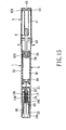
- the thirteenth preferred embodiment of a disposable syringe according to this invention is shown to be similar to the first embodiment in construction.
- the front seal member 325 of the carpule 3 is integrally formed with the tubular wall 32.
- the carpule 3 has a tubular needle holding portion 327 which extends forwardly from the mating surface 326 along the axis and which holds the communicating end 231 of the needle cannula 23 to communicate the needle cannula 23 with the sealed chamber 31.
- the carpule 3 further has an annular keyslot 37 which extends forwardly from the mating surface 326 in the axial direction to surround the needle holding portion 327.
- the seat member 22 has an annular key 224 which extends rearwardly from the gripped portion 222 and which is disposed to slide in and along the keyslot 37. Moreover, an elastomeric packing 26 is stuffed in the tip protector 25 such that when the tip protector 25 is sleeved on the barrel wall 12, the tip end 232 of the needle cannula 23 is trapped in the elastomeric packing 26, thereby preventing fluid leakage.
- the fourteenthpreferredembodiment of a disposable syringe according to this invention is shown to be similar to the thirteenth embodiment in construction, except that the barrel 1 and the tubular touching member 16 are the same as those of the third embodiment.
- the disposable syringe of this invention has the following advantages:
Landscapes
- Health & Medical Sciences (AREA)
- Engineering & Computer Science (AREA)
- Heart & Thoracic Surgery (AREA)
- Vascular Medicine (AREA)
- Anesthesiology (AREA)
- Biomedical Technology (AREA)
- Environmental & Geological Engineering (AREA)
- Hematology (AREA)
- Life Sciences & Earth Sciences (AREA)
- Animal Behavior & Ethology (AREA)
- General Health & Medical Sciences (AREA)
- Public Health (AREA)
- Veterinary Medicine (AREA)
- Infusion, Injection, And Reservoir Apparatuses (AREA)
- Containers And Packaging Bodies Having A Special Means To Remove Contents (AREA)
Priority Applications (3)
| Application Number | Priority Date | Filing Date | Title |
|---|---|---|---|
| DE602006007156T DE602006007156D1 (de) | 2006-11-29 | 2006-11-29 | Einwegspritze mit eingebauter Karpulle |
| EP06256102A EP1927372B1 (de) | 2006-11-29 | 2006-11-29 | Einwegspritze mit eingebauter Karpulle |
| AT06256102T ATE432726T1 (de) | 2006-11-29 | 2006-11-29 | Einwegspritze mit eingebauter karpulle |
Applications Claiming Priority (1)
| Application Number | Priority Date | Filing Date | Title |
|---|---|---|---|
| EP06256102A EP1927372B1 (de) | 2006-11-29 | 2006-11-29 | Einwegspritze mit eingebauter Karpulle |
Publications (2)
| Publication Number | Publication Date |
|---|---|
| EP1927372A1 true EP1927372A1 (de) | 2008-06-04 |
| EP1927372B1 EP1927372B1 (de) | 2009-06-03 |
Family
ID=37963447
Family Applications (1)
| Application Number | Title | Priority Date | Filing Date |
|---|---|---|---|
| EP06256102A Not-in-force EP1927372B1 (de) | 2006-11-29 | 2006-11-29 | Einwegspritze mit eingebauter Karpulle |
Country Status (3)
| Country | Link |
|---|---|
| EP (1) | EP1927372B1 (de) |
| AT (1) | ATE432726T1 (de) |
| DE (1) | DE602006007156D1 (de) |
Cited By (7)
| Publication number | Priority date | Publication date | Assignee | Title |
|---|---|---|---|---|
| ITVI20090252A1 (it) * | 2009-10-19 | 2011-04-20 | Brev Angela Srl | Siringa pre-riempita per iniezioni |
| WO2013186736A3 (en) * | 2012-06-15 | 2014-03-06 | Alexander Markus Oelz | Oral medicine dispensing system |
| WO2014045392A1 (ja) * | 2012-09-21 | 2014-03-27 | テルモ株式会社 | シリンジ |
| JP2014528820A (ja) * | 2011-10-14 | 2014-10-30 | アムジエン・インコーポレーテツド | 注入器および組立方法 |
| US10850037B2 (en) | 2013-03-22 | 2020-12-01 | Amgen Inc. | Injector and method of assembly |
| US10940091B2 (en) | 2012-06-15 | 2021-03-09 | Alexander Markus Oelz | Oral medicine dispensing system |
| US11097055B2 (en) | 2013-10-24 | 2021-08-24 | Amgen Inc. | Injector and method of assembly |
Families Citing this family (3)
| Publication number | Priority date | Publication date | Assignee | Title |
|---|---|---|---|---|
| GB0900930D0 (en) | 2009-01-20 | 2009-03-04 | Future Injection Technologies Ltd | Injection device |
| BR112012024238A2 (pt) | 2010-03-25 | 2019-09-24 | New Injection Systems Ltd | injetor |
| CA2890764C (en) | 2012-11-23 | 2021-05-04 | New Injection Systems Ltd | Auto-injector assembly |
Citations (4)
| Publication number | Priority date | Publication date | Assignee | Title |
|---|---|---|---|---|
| WO1998013077A2 (en) * | 1996-09-03 | 1998-04-02 | Mdc Investment Holdings, Inc. | Pre-filled retractable needle injection devices |
| WO1999030759A2 (en) * | 1997-12-16 | 1999-06-24 | Meridian Medical Technologies, Inc. | Automatic injector for administrating a medicament |
| WO2001007104A1 (de) * | 1999-07-27 | 2001-02-01 | Pharma Consult Ges.M.B.H. | Vorrichtung zum automatischen injizieren von injektionsflüssigkeiten |
| US6221055B1 (en) * | 1998-03-04 | 2001-04-24 | Retractable Technologies, Inc. | Retractable dental syringe |
-
2006
- 2006-11-29 EP EP06256102A patent/EP1927372B1/de not_active Not-in-force
- 2006-11-29 AT AT06256102T patent/ATE432726T1/de not_active IP Right Cessation
- 2006-11-29 DE DE602006007156T patent/DE602006007156D1/de active Active
Patent Citations (4)
| Publication number | Priority date | Publication date | Assignee | Title |
|---|---|---|---|---|
| WO1998013077A2 (en) * | 1996-09-03 | 1998-04-02 | Mdc Investment Holdings, Inc. | Pre-filled retractable needle injection devices |
| WO1999030759A2 (en) * | 1997-12-16 | 1999-06-24 | Meridian Medical Technologies, Inc. | Automatic injector for administrating a medicament |
| US6221055B1 (en) * | 1998-03-04 | 2001-04-24 | Retractable Technologies, Inc. | Retractable dental syringe |
| WO2001007104A1 (de) * | 1999-07-27 | 2001-02-01 | Pharma Consult Ges.M.B.H. | Vorrichtung zum automatischen injizieren von injektionsflüssigkeiten |
Cited By (22)
| Publication number | Priority date | Publication date | Assignee | Title |
|---|---|---|---|---|
| ITVI20090252A1 (it) * | 2009-10-19 | 2011-04-20 | Brev Angela Srl | Siringa pre-riempita per iniezioni |
| US9987428B2 (en) | 2011-10-14 | 2018-06-05 | Amgen Inc. | Injector and method of assembly |
| US11298463B2 (en) | 2011-10-14 | 2022-04-12 | Amgen Inc. | Method of assembling and filling a drug delivery device |
| JP2014528820A (ja) * | 2011-10-14 | 2014-10-30 | アムジエン・インコーポレーテツド | 注入器および組立方法 |
| US11273260B2 (en) | 2011-10-14 | 2022-03-15 | Amgen Inc. | Injector and method of assembly |
| US12329943B2 (en) | 2011-10-14 | 2025-06-17 | Amgen Inc. | Injector and method of assembly |
| US11110225B2 (en) | 2011-10-14 | 2021-09-07 | Amgen Inc. | Injector and method of assembly |
| US10314976B2 (en) | 2011-10-14 | 2019-06-11 | Amgen Inc. | Method of assembling and filling a drug delivery device |
| US10537682B2 (en) | 2011-10-14 | 2020-01-21 | Amgen Inc. | Injector and method of assembly |
| US10537681B2 (en) | 2011-10-14 | 2020-01-21 | Amgen Inc. | Injector and method of assembly |
| US11160931B2 (en) | 2011-10-14 | 2021-11-02 | Amgen Inc. | Method of assembling and filling a drug delivery device |
| US11129941B2 (en) | 2011-10-14 | 2021-09-28 | Amgen Inc. | Method of assembling and filling a drug delivery device |
| US11058821B2 (en) | 2011-10-14 | 2021-07-13 | Amgen Inc. | Injector and method of assembly |
| US9974712B2 (en) | 2012-06-15 | 2018-05-22 | Alexander Markus Oelz | Oral medicine dispensing system |
| US10940091B2 (en) | 2012-06-15 | 2021-03-09 | Alexander Markus Oelz | Oral medicine dispensing system |
| AU2013276148B2 (en) * | 2012-06-15 | 2016-12-15 | Robert James Martin | Oral medicine dispensing system |
| WO2013186736A3 (en) * | 2012-06-15 | 2014-03-06 | Alexander Markus Oelz | Oral medicine dispensing system |
| WO2014045392A1 (ja) * | 2012-09-21 | 2014-03-27 | テルモ株式会社 | シリンジ |
| US10850037B2 (en) | 2013-03-22 | 2020-12-01 | Amgen Inc. | Injector and method of assembly |
| US11759571B2 (en) | 2013-03-22 | 2023-09-19 | Amgen Inc. | Injector and method of assembly |
| US11097055B2 (en) | 2013-10-24 | 2021-08-24 | Amgen Inc. | Injector and method of assembly |
| US12427260B2 (en) | 2013-10-24 | 2025-09-30 | Amgen Inc. | Injector and method of assembly |
Also Published As
| Publication number | Publication date |
|---|---|
| ATE432726T1 (de) | 2009-06-15 |
| DE602006007156D1 (de) | 2009-07-16 |
| EP1927372B1 (de) | 2009-06-03 |
Similar Documents
| Publication | Publication Date | Title |
|---|---|---|
| US20070276338A1 (en) | Disposable syringe with built-in carpule | |
| TWI651108B (zh) | 活塞驅動式自動注射器 | |
| US7458962B2 (en) | Retractable needle medical device for injecting fluid from a pre-filled cartridge | |
| US7699813B2 (en) | Medical needle assemblies | |
| US5593391A (en) | Ampule safety syringe | |
| CN102131539B (zh) | 一种可缩回注射器 | |
| CN102665801A (zh) | 药物输送装置 | |
| AU2016417702B2 (en) | A safety housing based implant/ medicament injecting system | |
| JPH0211163A (ja) | 注射器 | |
| EP1927372B1 (de) | Einwegspritze mit eingebauter Karpulle | |
| US8303540B2 (en) | Pre-filled disposable syringe | |
| CN104302335B (zh) | 安全注射器和针头屏蔽件 | |
| US20090124970A1 (en) | Disposable syringe with built-in carpule | |
| NZ530509A (en) | Single-use syringe | |
| AU2007229353B2 (en) | Disposable syringe with built-in carpule | |
| JP4598400B2 (ja) | 自動注射針引込み式安全注射器 | |
| EP2246085A1 (de) | Einwegspritze mit eingebauter Karpulle | |
| CA2323923A1 (en) | Pre-filled retractable needle injection device | |
| CA2610129A1 (en) | Disposable syringe with built-in carpule | |
| EP2246082A1 (de) | Vorgefüllte Einwegspritze | |
| US20080234636A1 (en) | Disposable syringe guarded in a preuse position (1) | |
| CA2813475A1 (en) | Injection device comprising an injection needle | |
| CN217854076U (zh) | 一种自动注射器 | |
| KR200279650Y1 (ko) | 안전 채혈주사기 | |
| EP2039383A1 (de) | In Vorgebrauchsposition geschützte Einweg-Spritze (II) |
Legal Events
| Date | Code | Title | Description |
|---|---|---|---|
| PUAI | Public reference made under article 153(3) epc to a published international application that has entered the european phase |
Free format text: ORIGINAL CODE: 0009012 |
|
| 17P | Request for examination filed |
Effective date: 20061206 |
|
| AK | Designated contracting states |
Kind code of ref document: A1 Designated state(s): AT BE BG CH CY CZ DE DK EE ES FI FR GB GR HU IE IS IT LI LT LU LV MC NL PL PT RO SE SI SK TR |
|
| AX | Request for extension of the european patent |
Extension state: AL BA HR MK RS |
|
| GRAP | Despatch of communication of intention to grant a patent |
Free format text: ORIGINAL CODE: EPIDOSNIGR1 |
|
| AKX | Designation fees paid |
Designated state(s): AT BE BG CH CY CZ DE DK EE ES FI FR GB GR HU IE IS IT LI LT LU LV MC NL PL PT RO SE SI SK TR |
|
| GRAS | Grant fee paid |
Free format text: ORIGINAL CODE: EPIDOSNIGR3 |
|
| GRAA | (expected) grant |
Free format text: ORIGINAL CODE: 0009210 |
|
| AK | Designated contracting states |
Kind code of ref document: B1 Designated state(s): AT BE BG CH CY CZ DE DK EE ES FI FR GB GR HU IE IS IT LI LT LU LV MC NL PL PT RO SE SI SK TR |
|
| REG | Reference to a national code |
Ref country code: GB Ref legal event code: FG4D |
|
| REG | Reference to a national code |
Ref country code: CH Ref legal event code: EP |
|
| REG | Reference to a national code |
Ref country code: IE Ref legal event code: FG4D |
|
| REF | Corresponds to: |
Ref document number: 602006007156 Country of ref document: DE Date of ref document: 20090716 Kind code of ref document: P |
|
| PG25 | Lapsed in a contracting state [announced via postgrant information from national office to epo] |
Ref country code: AT Free format text: LAPSE BECAUSE OF FAILURE TO SUBMIT A TRANSLATION OF THE DESCRIPTION OR TO PAY THE FEE WITHIN THE PRESCRIBED TIME-LIMIT Effective date: 20090603 Ref country code: FI Free format text: LAPSE BECAUSE OF FAILURE TO SUBMIT A TRANSLATION OF THE DESCRIPTION OR TO PAY THE FEE WITHIN THE PRESCRIBED TIME-LIMIT Effective date: 20090603 Ref country code: LT Free format text: LAPSE BECAUSE OF FAILURE TO SUBMIT A TRANSLATION OF THE DESCRIPTION OR TO PAY THE FEE WITHIN THE PRESCRIBED TIME-LIMIT Effective date: 20090603 |
|
| NLV1 | Nl: lapsed or annulled due to failure to fulfill the requirements of art. 29p and 29m of the patents act | ||
| PG25 | Lapsed in a contracting state [announced via postgrant information from national office to epo] |
Ref country code: PL Free format text: LAPSE BECAUSE OF FAILURE TO SUBMIT A TRANSLATION OF THE DESCRIPTION OR TO PAY THE FEE WITHIN THE PRESCRIBED TIME-LIMIT Effective date: 20090603 Ref country code: LV Free format text: LAPSE BECAUSE OF FAILURE TO SUBMIT A TRANSLATION OF THE DESCRIPTION OR TO PAY THE FEE WITHIN THE PRESCRIBED TIME-LIMIT Effective date: 20090603 Ref country code: NL Free format text: LAPSE BECAUSE OF FAILURE TO SUBMIT A TRANSLATION OF THE DESCRIPTION OR TO PAY THE FEE WITHIN THE PRESCRIBED TIME-LIMIT Effective date: 20090603 Ref country code: SE Free format text: LAPSE BECAUSE OF FAILURE TO SUBMIT A TRANSLATION OF THE DESCRIPTION OR TO PAY THE FEE WITHIN THE PRESCRIBED TIME-LIMIT Effective date: 20090903 Ref country code: SI Free format text: LAPSE BECAUSE OF FAILURE TO SUBMIT A TRANSLATION OF THE DESCRIPTION OR TO PAY THE FEE WITHIN THE PRESCRIBED TIME-LIMIT Effective date: 20090603 |
|
| PG25 | Lapsed in a contracting state [announced via postgrant information from national office to epo] |
Ref country code: RO Free format text: LAPSE BECAUSE OF FAILURE TO SUBMIT A TRANSLATION OF THE DESCRIPTION OR TO PAY THE FEE WITHIN THE PRESCRIBED TIME-LIMIT Effective date: 20090603 Ref country code: CZ Free format text: LAPSE BECAUSE OF FAILURE TO SUBMIT A TRANSLATION OF THE DESCRIPTION OR TO PAY THE FEE WITHIN THE PRESCRIBED TIME-LIMIT Effective date: 20090603 Ref country code: EE Free format text: LAPSE BECAUSE OF FAILURE TO SUBMIT A TRANSLATION OF THE DESCRIPTION OR TO PAY THE FEE WITHIN THE PRESCRIBED TIME-LIMIT Effective date: 20090603 Ref country code: ES Free format text: LAPSE BECAUSE OF FAILURE TO SUBMIT A TRANSLATION OF THE DESCRIPTION OR TO PAY THE FEE WITHIN THE PRESCRIBED TIME-LIMIT Effective date: 20090914 Ref country code: IS Free format text: LAPSE BECAUSE OF FAILURE TO SUBMIT A TRANSLATION OF THE DESCRIPTION OR TO PAY THE FEE WITHIN THE PRESCRIBED TIME-LIMIT Effective date: 20091003 |
|
| PG25 | Lapsed in a contracting state [announced via postgrant information from national office to epo] |
Ref country code: BE Free format text: LAPSE BECAUSE OF FAILURE TO SUBMIT A TRANSLATION OF THE DESCRIPTION OR TO PAY THE FEE WITHIN THE PRESCRIBED TIME-LIMIT Effective date: 20090603 Ref country code: SK Free format text: LAPSE BECAUSE OF FAILURE TO SUBMIT A TRANSLATION OF THE DESCRIPTION OR TO PAY THE FEE WITHIN THE PRESCRIBED TIME-LIMIT Effective date: 20090603 |
|
| PG25 | Lapsed in a contracting state [announced via postgrant information from national office to epo] |
Ref country code: PT Free format text: LAPSE BECAUSE OF FAILURE TO SUBMIT A TRANSLATION OF THE DESCRIPTION OR TO PAY THE FEE WITHIN THE PRESCRIBED TIME-LIMIT Effective date: 20091003 Ref country code: BG Free format text: LAPSE BECAUSE OF FAILURE TO SUBMIT A TRANSLATION OF THE DESCRIPTION OR TO PAY THE FEE WITHIN THE PRESCRIBED TIME-LIMIT Effective date: 20090903 |
|
| PLBE | No opposition filed within time limit |
Free format text: ORIGINAL CODE: 0009261 |
|
| STAA | Information on the status of an ep patent application or granted ep patent |
Free format text: STATUS: NO OPPOSITION FILED WITHIN TIME LIMIT |
|
| PG25 | Lapsed in a contracting state [announced via postgrant information from national office to epo] |
Ref country code: DK Free format text: LAPSE BECAUSE OF FAILURE TO SUBMIT A TRANSLATION OF THE DESCRIPTION OR TO PAY THE FEE WITHIN THE PRESCRIBED TIME-LIMIT Effective date: 20090603 |
|
| 26N | No opposition filed |
Effective date: 20100304 |
|
| PG25 | Lapsed in a contracting state [announced via postgrant information from national office to epo] |
Ref country code: MC Free format text: LAPSE BECAUSE OF NON-PAYMENT OF DUE FEES Effective date: 20091130 |
|
| REG | Reference to a national code |
Ref country code: FR Ref legal event code: ST Effective date: 20100730 |
|
| PG25 | Lapsed in a contracting state [announced via postgrant information from national office to epo] |
Ref country code: FR Free format text: LAPSE BECAUSE OF NON-PAYMENT OF DUE FEES Effective date: 20091130 Ref country code: GR Free format text: LAPSE BECAUSE OF FAILURE TO SUBMIT A TRANSLATION OF THE DESCRIPTION OR TO PAY THE FEE WITHIN THE PRESCRIBED TIME-LIMIT Effective date: 20090904 Ref country code: IE Free format text: LAPSE BECAUSE OF NON-PAYMENT OF DUE FEES Effective date: 20091129 |
|
| REG | Reference to a national code |
Ref country code: FR Ref legal event code: RN |
|
| PG25 | Lapsed in a contracting state [announced via postgrant information from national office to epo] |
Ref country code: IT Free format text: LAPSE BECAUSE OF FAILURE TO SUBMIT A TRANSLATION OF THE DESCRIPTION OR TO PAY THE FEE WITHIN THE PRESCRIBED TIME-LIMIT Effective date: 20090603 |
|
| PG25 | Lapsed in a contracting state [announced via postgrant information from national office to epo] |
Ref country code: LU Free format text: LAPSE BECAUSE OF NON-PAYMENT OF DUE FEES Effective date: 20091129 |
|
| REG | Reference to a national code |
Ref country code: FR Ref legal event code: D3 |
|
| PG25 | Lapsed in a contracting state [announced via postgrant information from national office to epo] |
Ref country code: HU Free format text: LAPSE BECAUSE OF FAILURE TO SUBMIT A TRANSLATION OF THE DESCRIPTION OR TO PAY THE FEE WITHIN THE PRESCRIBED TIME-LIMIT Effective date: 20091204 |
|
| REG | Reference to a national code |
Ref country code: CH Ref legal event code: PL |
|
| PG25 | Lapsed in a contracting state [announced via postgrant information from national office to epo] |
Ref country code: LI Free format text: LAPSE BECAUSE OF NON-PAYMENT OF DUE FEES Effective date: 20101130 Ref country code: CH Free format text: LAPSE BECAUSE OF NON-PAYMENT OF DUE FEES Effective date: 20101130 |
|
| PG25 | Lapsed in a contracting state [announced via postgrant information from national office to epo] |
Ref country code: TR Free format text: LAPSE BECAUSE OF FAILURE TO SUBMIT A TRANSLATION OF THE DESCRIPTION OR TO PAY THE FEE WITHIN THE PRESCRIBED TIME-LIMIT Effective date: 20090603 |
|
| PG25 | Lapsed in a contracting state [announced via postgrant information from national office to epo] |
Ref country code: CY Free format text: LAPSE BECAUSE OF FAILURE TO SUBMIT A TRANSLATION OF THE DESCRIPTION OR TO PAY THE FEE WITHIN THE PRESCRIBED TIME-LIMIT Effective date: 20090603 |
|
| PGRI | Patent reinstated in contracting state [announced from national office to epo] |
Ref country code: FR Effective date: 20110405 |
|
| REG | Reference to a national code |
Ref country code: FR Ref legal event code: PLFP Year of fee payment: 11 |
|
| REG | Reference to a national code |
Ref country code: FR Ref legal event code: PLFP Year of fee payment: 12 |
|
| REG | Reference to a national code |
Ref country code: FR Ref legal event code: PLFP Year of fee payment: 13 |
|
| PGFP | Annual fee paid to national office [announced via postgrant information from national office to epo] |
Ref country code: FR Payment date: 20180926 Year of fee payment: 13 |
|
| PGFP | Annual fee paid to national office [announced via postgrant information from national office to epo] |
Ref country code: GB Payment date: 20180926 Year of fee payment: 13 |
|
| PGFP | Annual fee paid to national office [announced via postgrant information from national office to epo] |
Ref country code: DE Payment date: 20180927 Year of fee payment: 13 |
|
| REG | Reference to a national code |
Ref country code: DE Ref legal event code: R119 Ref document number: 602006007156 Country of ref document: DE |
|
| GBPC | Gb: european patent ceased through non-payment of renewal fee |
Effective date: 20191129 |
|
| PG25 | Lapsed in a contracting state [announced via postgrant information from national office to epo] |
Ref country code: DE Free format text: LAPSE BECAUSE OF NON-PAYMENT OF DUE FEES Effective date: 20200603 Ref country code: FR Free format text: LAPSE BECAUSE OF NON-PAYMENT OF DUE FEES Effective date: 20191130 Ref country code: GB Free format text: LAPSE BECAUSE OF NON-PAYMENT OF DUE FEES Effective date: 20191129 |