EP1927704A2 - Fourchette de sécurité - Google Patents
Fourchette de sécurité Download PDFInfo
- Publication number
- EP1927704A2 EP1927704A2 EP07254634A EP07254634A EP1927704A2 EP 1927704 A2 EP1927704 A2 EP 1927704A2 EP 07254634 A EP07254634 A EP 07254634A EP 07254634 A EP07254634 A EP 07254634A EP 1927704 A2 EP1927704 A2 EP 1927704A2
- Authority
- EP
- European Patent Office
- Prior art keywords
- fork
- clamp
- vertical
- side walls
- rolled section
- Prior art date
- Legal status (The legal status is an assumption and is not a legal conclusion. Google has not performed a legal analysis and makes no representation as to the accuracy of the status listed.)
- Granted
Links
Images

Classifications
-
- E—FIXED CONSTRUCTIONS
- E04—BUILDING
- E04B—GENERAL BUILDING CONSTRUCTIONS; WALLS, e.g. PARTITIONS; ROOFS; FLOORS; CEILINGS; INSULATION OR OTHER PROTECTION OF BUILDINGS
- E04B9/00—Ceilings; Construction of ceilings, e.g. false ceilings; Ceiling construction with regard to insulation
- E04B9/18—Means for suspending the supporting construction
- E04B9/20—Means for suspending the supporting construction adjustable
-
- E—FIXED CONSTRUCTIONS
- E04—BUILDING
- E04B—GENERAL BUILDING CONSTRUCTIONS; WALLS, e.g. PARTITIONS; ROOFS; FLOORS; CEILINGS; INSULATION OR OTHER PROTECTION OF BUILDINGS
- E04B9/00—Ceilings; Construction of ceilings, e.g. false ceilings; Ceiling construction with regard to insulation
- E04B9/18—Means for suspending the supporting construction
- E04B9/183—Means for suspending the supporting construction having a lower side adapted to be connected to a channel of the supporting construction
-
- E—FIXED CONSTRUCTIONS
- E04—BUILDING
- E04B—GENERAL BUILDING CONSTRUCTIONS; WALLS, e.g. PARTITIONS; ROOFS; FLOORS; CEILINGS; INSULATION OR OTHER PROTECTION OF BUILDINGS
- E04B9/00—Ceilings; Construction of ceilings, e.g. false ceilings; Ceiling construction with regard to insulation
- E04B9/18—Means for suspending the supporting construction
- E04B2009/186—Means for suspending the supporting construction with arrangements for damping vibration
Definitions
- This invention relates to a safety fork for fitting continuous false ceilings, in particular a fork with a sheet-type body in the form of an inverted "U" with flat walls which consist of an upper horizontal wall and two vertical side walls, the upper wall having a hole for the passage of a threaded rod anchored to the original ceiling of the enclosure and the side walls each having, on their vertical edges, grooves opposite each other for having inserted in them longitudinal opposed flanges of a "U"-shaped rolled section to which are screwed the prefabricated boards with which the continuous false ceiling is made, the fork of which has a prismatic block of an elastoplastic nature which, with a running fit, is inserted between its three walls, which is fitted on a support with a drill hole provided with a central drill hole [sic] aligned with the hole in the upper wall and which extends beyond the edges of the side walls where it forms tabs which rest in a sliding manner on these edges and the side walls of which are joined together by means of a tie provided with a
- an object of the invention is a means of safety which ensures the stability of the fitting against the continuous ceiling's being able to fall down due to a defect in construction or fitting or due to a calculation error.
- Another object of the invention is means capable of compensating for defects of inclination of the flat ceiling from which the continuous false ceiling is to be suspended.
- the process of fitting a continuous false ceiling consists, firstly, of anchoring the threaded rods to the original ceiling of the enclosure where the continuous false ceiling is being installed; then, the lower end of each rod successively passes through the hole in the fork upper wall, through the elastoplastic block and through the central drill hole in the latter's support, in order for it to be screwed into a nut with which it will be possible to adjust the height so as to obtain the correct levelling of the installation; subsequently, the rolled section is connected by means of an operation which consists, firstly, of inserting one of its longitudinal flanges in the grooves of one single side of both vertical side walls of the fork and, secondly, of pushing upwards so that, due to the elastic nature of the rolled section, there is a widening of the upper opening of the latter until the other longitudinal flange reaches the opposite grooves in the said vertical side walls of the fork and penetrates them; to finish, the continuous false ceiling prefabricated boards are screwed on to the bottom or web of the
- a known solution for these purposes is that of Spanish Utility Model U-200001684 , in which there is a fork which has, welded between its vertical side walls, a tie provided with a central hole through which it is possible to fit a sheet metal tapping screw which passes through both of the rolled section's sides, so that this screw offers resistance to the opening-out of the section;
- this solution uses, as a vibration damping element, the conventional rubber block in a circular-generated shape, which is fitted between the fork side walls and has a neck which passes through the hole in the fork's upper wall.
- Another problem which is present in this type of fitting is that of the lack of horizontality of a flat ceiling to which it is desired to fit a horizontal continuous false ceiling, whether this is due to a defect in the construction of the flat ceiling or because the latter intentionally has a certain inclination.
- the solution proposed in this invention consists of there being, with a running fit between the fork's side walls, a sheet-type clamp in the shape of a bridge which determines two vertical legs and one upper side, the vertical legs of which each have holes which are aligned with each other and with the central hole in the tie and the upper side of which, on its side edges, has projections which have a running fit in respective vertical guides which are formed in the fork's side walls, so that the said clamp is capable of adopting upper and lower operating positions such that, in the upper position, the projections are at the upper end of the vertical guides and the vertical legs are above the level of the rolled section's longitudinal flanges whereas, in the lower position, the projections are at the lower end of the vertical guides and the vertical legs are placed on the outside of the rolled section's vertical sides and there is a sheet metal tapping screw which, in this lower position of the clamp, is capable of being met by at least one of the holes in this clamp's vertical legs and by the central hole of the
- fitting is simple: once the fork is suspended from the rod anchored to the enclosure ceiling, the clamp is held in its upper position; then the rolled section is connected, the clamp is dropped and the sheet metal tapping screw is fitted; finally, the prefabricated boards are fastened to the base of the rolled section.
- Another feature of the invention consists of the clamp's vertical legs' having a profile which is slightly convex towards the inside, which gives the clamp a shape reminiscent of the Greek letter omega. This configuration assists better operating adaptation to the rolled section, compensating for dimensional differences which are frequent, depending on who the manufacturer is and taking into account that, due to its nature, this element is not of high precision.
- Another feature of the invention consists of the upper wall's incorporating, in a rigidly fastened manner, a bell with the shape of a one-base spherical segment which has an upper central opening and which, inside, houses, with a running fit, a ball and socket joint which screws along the threaded rod and which emerges from the bell by means of a neck which, with suitable clearance, passes through the said central opening in the bell and which, now outside the bell, widens to form a flat disc, the periphery of which is knurled.
- the attached drawings illustrate a preferred embodiment of the object of the invention, relating to a safety fork for fitting continuous false ceilings, which corresponds to a constitution in which the fork (1) has a sheet-type body in the form of an inverted "U" with flat walls which consist of an upper horizontal wall (1a) and two vertical side walls (1b), the upper wall (1a) having a hole for the passage of a threaded rod (6) anchored to the original ceiling (7) of the enclosure and the side walls (1b) each having, on their vertical edges, grooves (1c) opposite each other for having inserted in them longitudinal opposed flanges (8a) of a "U"-shaped rolled section (8) to which are screwed the prefabricated boards (9) with which the continuous false ceiling is made, the fork (1) of which has a prismatic block (2) of an elastoplastic nature which, with a running fit, is inserted between its three walls (1 a, 1 b), which is fitted on a support (5) with a drill hole provided
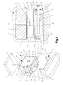
- FIG. 1 The particular constitution of the invention is illustrated in figure 1 . It consists of there being, with a running fit between the fork (1) side walls (1 b), a sheet-type clamp (4) in the shape of a bridge which determines two vertical legs (4a) and one upper side (4b), the vertical legs (4a) of which each have holes (4c) which are aligned with each other and with the central hole (3a) in the tie (3) and the upper side (4b) of which, on its side edges, has projections (4d) which have a running fit in respective vertical guides (1d) which are formed in the fork (1) side walls (1 b), so that the said clamp (4) is capable of adopting upper and lower operating positions such that, in the upper position, the projections (4d) are at the upper end of the vertical guides (1d) and the vertical legs (4a) are above the level of the rolled section (8) longitudinal flanges (8a) whereas, in the lower position, the projections (4d) are at the lower end of the vertical guides (1d) and the vertical legs (4a)
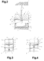
- the functionality of the fork advocated is shown in the simplicity and speed of the fitting operation and in the safety and strength of the fitting, as is gathered from comparing the pairs of figures 1 (the section)-2 and 3-4.
- the procedure is ( figure 3 ) to take the clamp (4) projections (4d) in the fingers and move the clamp to its upper position to carry out the connection by pushing the rolled section (8), with the result that the longitudinal flanges (8a) are inserted in the grooves (1c) in the fork (1) side walls (1 b); then, fingers are taken away and, due to gravity, the clamp (4) drops ( figure 1 ) and the sheet metal tapping screw (10) can be put in place through the hole (4c) in the clamp (4) vertical leg (4a), through the side of the rolled section (8) and through the central hole (3a) in the tie (3); finally, the continuous false ceiling prefabricated boards (9) are fastened to the base of the rolled section (8).
- the attached drawings illustrate a preferred embodiment of the object of the invention, relating to a safety fork for fitting continuous false ceilings, which corresponds to a constitution in which the fork (1) has a sheet-type body in the form of an inverted "U" with flat walls which consist of an upper horizontal wall (1 a) and two vertical side walls (1 b), the upper wall (1a) having a hole for the passage of a threaded rod (6) anchored to the original ceiling (7) of the enclosure and the side walls (1 b) each having, on their vertical edges, grooves (1 c) opposite each other for having inserted in them longitudinal opposed flanges (8a) of a "U"-shaped rolled section (8) to which are screwed the prefabricated boards (9) with which the continuous false ceiling is made, the fork (1) of which has ( figures 16 and 17 ) a prismatic block (2) of an elastoplastic nature which, with a running fit, is inserted between its three walls (1a, 1b), which is fitted on a
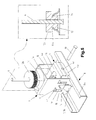
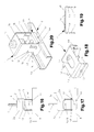
- FIG. 5 The particular constitution of the invention is illustrated in figure 5 . It consists of there being, with a running fit between the fork (1) side walls (1 b), a sheet-type clamp (4) in the shape of a bridge which determines two vertical legs (4a) and one upper side (4b), the vertical legs (4a) of which each have holes (4c) which are aligned with each other and with a central hole (3a) in a tie (3) which connects the side walls (1 b) and the upper side (4b) of which, on its side edges, has pairs of tongues (4f) which have a running fit in respective vertical guides (1e) which, at their upper end, are angled in an "L" shape, forming a horizontal section (1f) in which their height has a running fit relating to the thickness of the said tongues (4f), so that the said clamp (4) is capable of adopting upper and lower operating positions such that, in the upper position, the clamp (4) is displaced sideways with the tongues (4f) housed in the horizontal sections (1f) of the vertical guides
- the tie (3) be welded between the side walls (1 b) once the clamp (4) has been fitted with its side tongues (4f) inserted in their vertical guides (1e), so that the end result is one of great strength which makes the fork (1) non-deformable and prevents the possibility that the clamp (4) can be removed, which prevents losses during transport and simplifies the operation of fitting to the rolled section (8).
- the upper side (4b) of the clamp (4) there is an opening (4e) of greater width than a nut (11) screwed on to the lower end of the threaded rod (6).
- the clamp (4) is situated as illustrated by figures 5 , 7 , 12, 13 and 16 , i.e. in the upper position and with its side tongues (4f) inserted in the horizontal sections (1f) of their vertical guides (1e). Then, it is connected to the rolled section (8), the longitudinal flanges (8a) of the latter being inserted in the grooves (1 c) in the edges of the vertical walls (1 b) by pushing with an elastic jumping motion.
- the clamp (4) is moved so that the tongues (4f) come out of the said horizontal sections (1f) and so that it can descend to its lower position which is shown by figures 6 , 14, 15-15A and 17 ; in this position, the clamp (4) is trapping the rolled section (8) on the outside.
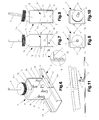
- another feature of the invention is ( figures 18 and 19 ) that the clamp (4) vertical legs (4a) have a profile which is slightly convex towards the inside, which gives the clamp (4) a shape reminiscent of the Greek letter omega, by means of which, as can be appreciated with greater clarity in figure 15A , a dimensional adjustment function is obtained, which compensates for the size differences which generally occur in the manufacture of the rolled section (8), depending on who its manufacturer is.
- the upper wall (1a) incorporates, in a rigidly fastened manner, a bell (1g) with the shape of a one-base spherical segment which has an upper central opening (1 h) and which, inside, houses, with a running fit, a ball and socket joint (12) which screws along the threaded rod (6) and which emerges from the bell (1g) by means of a neck (12a) which, with suitable clearance, passes through the said central opening (1 h) in the bell and which, now outside the bell (1g), widens to form a flat disc (12b), the periphery of which is knurled; in accordance with a preferred embodiment, the bell (1g) is integral with the upper wall (1a).
- the version of fork (1) has been chosen which has a bell (1g), in particular that in which the bell (1g) is integral with the fork (1) itself but, as figures 16 and 17 illustrate, the function assigned to the clamp (4) according to figures 18 and 19 is perfectly compatible with forks (1) without a bell (1g).
- the knurled periphery of the flat disc (12b) serves to simplify the operation of height regulation by means of screwing on the threaded rod (6).
- FIG 20 Another embodiment of the invention ( figure 20 ) shows the fork advocated in which the elastoplastic prismatic block (2) has been replaced with an ordinary cylindrical rubber block (13).
- tie (3) side walls (3b) be welded to the fork (1) side walls (1b) after insertion of the clamp (4) side tongues (4f) in the respective vertical guides (1e) of the fork (1), ensuring dimensional stability and therefore the non-dismantlable nature of the assembly.
Landscapes
- Engineering & Computer Science (AREA)
- Architecture (AREA)
- Physics & Mathematics (AREA)
- Electromagnetism (AREA)
- Civil Engineering (AREA)
- Structural Engineering (AREA)
- Clamps And Clips (AREA)
- Forklifts And Lifting Vehicles (AREA)
Applications Claiming Priority (2)
| Application Number | Priority Date | Filing Date | Title |
|---|---|---|---|
| ES200603062A ES2320952B1 (es) | 2006-11-29 | 2006-11-29 | Horquilla de seguridad para montaje de falsos techos continuos. |
| ES200702692A ES2324382B1 (es) | 2007-10-15 | 2007-10-15 | Horquilla con medios de seguridad para montaje de falsos techos continuos. |
Publications (3)
| Publication Number | Publication Date |
|---|---|
| EP1927704A2 true EP1927704A2 (fr) | 2008-06-04 |
| EP1927704A3 EP1927704A3 (fr) | 2010-06-30 |
| EP1927704B1 EP1927704B1 (fr) | 2013-05-29 |
Family
ID=39106295
Family Applications (1)
| Application Number | Title | Priority Date | Filing Date |
|---|---|---|---|
| EP20070254634 Active EP1927704B1 (fr) | 2006-11-29 | 2007-11-29 | Ensemble de sécurité |
Country Status (1)
| Country | Link |
|---|---|
| EP (1) | EP1927704B1 (fr) |
Cited By (6)
| Publication number | Priority date | Publication date | Assignee | Title |
|---|---|---|---|---|
| JP2013023855A (ja) * | 2011-07-19 | 2013-02-04 | Sawata Co Ltd | 天井下地用クリップ金具 |
| EP2803779A1 (fr) * | 2013-05-16 | 2014-11-19 | Michael Reichhard | Système de fixation d'un rail |
| JP2015218534A (ja) * | 2014-05-20 | 2015-12-07 | 倉敷化工株式会社 | 防振吊り金具 |
| EP3216932A1 (fr) * | 2016-03-07 | 2017-09-13 | Knauf Insulation SPRL | Structure de construction isolée |
| US10174501B1 (en) * | 2017-09-06 | 2019-01-08 | Usg Interiors, Llc | Metal baffles |
| EP3660238A3 (fr) * | 2018-11-27 | 2020-06-10 | Akifix S.P.A. | Système d'ancrage pour faux plafonds |
Citations (2)
| Publication number | Priority date | Publication date | Assignee | Title |
|---|---|---|---|---|
| ES1046596U (es) | 2000-06-22 | 2001-01-01 | Galarraca Ignacio Lopetegui | Horquilla de seguridad para fijacion de techos continuos y similares. |
| ES2277489A1 (es) | 2004-11-22 | 2007-07-01 | Maiztarkoetxea, S.L. | Dispositivo de horquilla de seguridad para montaje de falsos techos continuos. |
Family Cites Families (1)
| Publication number | Priority date | Publication date | Assignee | Title |
|---|---|---|---|---|
| FR1388940A (fr) * | 1963-12-31 | 1965-02-12 | Perfectionnements apportés aux ensembles, notamment du genre des faux-plafonds, comportant des assemblages des assemblages de profilés |
-
2007
- 2007-11-29 EP EP20070254634 patent/EP1927704B1/fr active Active
Patent Citations (2)
| Publication number | Priority date | Publication date | Assignee | Title |
|---|---|---|---|---|
| ES1046596U (es) | 2000-06-22 | 2001-01-01 | Galarraca Ignacio Lopetegui | Horquilla de seguridad para fijacion de techos continuos y similares. |
| ES2277489A1 (es) | 2004-11-22 | 2007-07-01 | Maiztarkoetxea, S.L. | Dispositivo de horquilla de seguridad para montaje de falsos techos continuos. |
Cited By (6)
| Publication number | Priority date | Publication date | Assignee | Title |
|---|---|---|---|---|
| JP2013023855A (ja) * | 2011-07-19 | 2013-02-04 | Sawata Co Ltd | 天井下地用クリップ金具 |
| EP2803779A1 (fr) * | 2013-05-16 | 2014-11-19 | Michael Reichhard | Système de fixation d'un rail |
| JP2015218534A (ja) * | 2014-05-20 | 2015-12-07 | 倉敷化工株式会社 | 防振吊り金具 |
| EP3216932A1 (fr) * | 2016-03-07 | 2017-09-13 | Knauf Insulation SPRL | Structure de construction isolée |
| US10174501B1 (en) * | 2017-09-06 | 2019-01-08 | Usg Interiors, Llc | Metal baffles |
| EP3660238A3 (fr) * | 2018-11-27 | 2020-06-10 | Akifix S.P.A. | Système d'ancrage pour faux plafonds |
Also Published As
| Publication number | Publication date |
|---|---|
| EP1927704B1 (fr) | 2013-05-29 |
| EP1927704A3 (fr) | 2010-06-30 |
Similar Documents
| Publication | Publication Date | Title |
|---|---|---|
| EP1927704B1 (fr) | Ensemble de sécurité | |
| US4448003A (en) | Tube connections | |
| WO2006023045A3 (fr) | Fixation et ensemble de montage pour poteau de cloture | |
| AU2009201902B2 (en) | Suspended ceiling gusset stay | |
| US20110290948A1 (en) | Pipe-suspension bracket | |
| US7861470B2 (en) | Self centering shaft wall system | |
| CN106049692B (zh) | 一种轻钢房屋连接结构 | |
| US10743663B2 (en) | Seismic baseplate | |
| JP2016528408A (ja) | 建築用足場装置の足場管及び足場要素 | |
| CN108222545B (zh) | 一种预制楼板支撑装置 | |
| US20060237263A1 (en) | Safety rail for roofing; method of use and of manufacture | |
| US8357295B2 (en) | Adjustable anchor rod | |
| KR102149173B1 (ko) | 세트 앙카 | |
| US8186283B2 (en) | Cradle and leg joints for customizable furniture | |
| CN205713158U (zh) | 一种分段式皮数杆 | |
| KR101536657B1 (ko) | 채널의 상부 고정장치 및 이를 이용한 채널의 설치공법 | |
| JP2011256677A (ja) | 天井消火システム | |
| EP1630320A2 (fr) | Systèmes modulaires pour la confection de mains courantes | |
| KR101279703B1 (ko) | 케이블카용 객실 | |
| EP2110488A2 (fr) | Ensemble de plafond | |
| KR20200006394A (ko) | 전산볼트 체결이 용이한 배관용 파이프 행거 | |
| CN214614933U (zh) | 一种适用于钢结构建筑的调平结构 | |
| CN222390983U (zh) | 一种房屋建筑外墙保温一体板与铝合金模板的固定装置 | |
| CN112554422A (zh) | 一种适用于钢结构建筑的调平结构及安装方法 | |
| SE466112B (sv) | Anordning vid en samverkanpelare samt saett foer tillverkning av en dylik anordning |
Legal Events
| Date | Code | Title | Description |
|---|---|---|---|
| PUAI | Public reference made under article 153(3) epc to a published international application that has entered the european phase |
Free format text: ORIGINAL CODE: 0009012 |
|
| AK | Designated contracting states |
Kind code of ref document: A2 Designated state(s): AT BE BG CH CY CZ DE DK EE ES FI FR GB GR HU IE IS IT LI LT LU LV MC MT NL PL PT RO SE SI SK TR |
|
| AX | Request for extension of the european patent |
Extension state: AL BA HR MK RS |
|
| PUAL | Search report despatched |
Free format text: ORIGINAL CODE: 0009013 |
|
| AK | Designated contracting states |
Kind code of ref document: A3 Designated state(s): AT BE BG CH CY CZ DE DK EE ES FI FR GB GR HU IE IS IT LI LT LU LV MC MT NL PL PT RO SE SI SK TR |
|
| AX | Request for extension of the european patent |
Extension state: AL BA HR MK RS |
|
| 17P | Request for examination filed |
Effective date: 20100804 |
|
| AKX | Designation fees paid |
Designated state(s): AT BE BG CH CY CZ DE DK EE ES FI FR GB GR HU IE IS IT LI LT LU LV MC MT NL PL PT RO SE SI SK TR |
|
| GRAP | Despatch of communication of intention to grant a patent |
Free format text: ORIGINAL CODE: EPIDOSNIGR1 |
|
| GRAS | Grant fee paid |
Free format text: ORIGINAL CODE: EPIDOSNIGR3 |
|
| GRAA | (expected) grant |
Free format text: ORIGINAL CODE: 0009210 |
|
| AK | Designated contracting states |
Kind code of ref document: B1 Designated state(s): AT BE BG CH CY CZ DE DK EE ES FI FR GB GR HU IE IS IT LI LT LU LV MC MT NL PL PT RO SE SI SK TR |
|
| REG | Reference to a national code |
Ref country code: GB Ref legal event code: FG4D |
|
| REG | Reference to a national code |
Ref country code: CH Ref legal event code: EP |
|
| REG | Reference to a national code |
Ref country code: AT Ref legal event code: REF Ref document number: 614508 Country of ref document: AT Kind code of ref document: T Effective date: 20130615 |
|
| REG | Reference to a national code |
Ref country code: IE Ref legal event code: FG4D |
|
| REG | Reference to a national code |
Ref country code: DE Ref legal event code: R096 Ref document number: 602007030744 Country of ref document: DE Effective date: 20130725 |
|
| REG | Reference to a national code |
Ref country code: SE Ref legal event code: TRGR |
|
| REG | Reference to a national code |
Ref country code: AT Ref legal event code: MK05 Ref document number: 614508 Country of ref document: AT Kind code of ref document: T Effective date: 20130529 |
|
| REG | Reference to a national code |
Ref country code: LT Ref legal event code: MG4D |
|
| PG25 | Lapsed in a contracting state [announced via postgrant information from national office to epo] |
Ref country code: ES Free format text: LAPSE BECAUSE OF FAILURE TO SUBMIT A TRANSLATION OF THE DESCRIPTION OR TO PAY THE FEE WITHIN THE PRESCRIBED TIME-LIMIT Effective date: 20130909 Ref country code: AT Free format text: LAPSE BECAUSE OF FAILURE TO SUBMIT A TRANSLATION OF THE DESCRIPTION OR TO PAY THE FEE WITHIN THE PRESCRIBED TIME-LIMIT Effective date: 20130529 Ref country code: IS Free format text: LAPSE BECAUSE OF FAILURE TO SUBMIT A TRANSLATION OF THE DESCRIPTION OR TO PAY THE FEE WITHIN THE PRESCRIBED TIME-LIMIT Effective date: 20130929 Ref country code: LT Free format text: LAPSE BECAUSE OF FAILURE TO SUBMIT A TRANSLATION OF THE DESCRIPTION OR TO PAY THE FEE WITHIN THE PRESCRIBED TIME-LIMIT Effective date: 20130529 Ref country code: SI Free format text: LAPSE BECAUSE OF FAILURE TO SUBMIT A TRANSLATION OF THE DESCRIPTION OR TO PAY THE FEE WITHIN THE PRESCRIBED TIME-LIMIT Effective date: 20130529 Ref country code: PT Free format text: LAPSE BECAUSE OF FAILURE TO SUBMIT A TRANSLATION OF THE DESCRIPTION OR TO PAY THE FEE WITHIN THE PRESCRIBED TIME-LIMIT Effective date: 20130930 |
|
| REG | Reference to a national code |
Ref country code: NL Ref legal event code: VDEP Effective date: 20130529 |
|
| PG25 | Lapsed in a contracting state [announced via postgrant information from national office to epo] |
Ref country code: PL Free format text: LAPSE BECAUSE OF FAILURE TO SUBMIT A TRANSLATION OF THE DESCRIPTION OR TO PAY THE FEE WITHIN THE PRESCRIBED TIME-LIMIT Effective date: 20130529 Ref country code: BG Free format text: LAPSE BECAUSE OF FAILURE TO SUBMIT A TRANSLATION OF THE DESCRIPTION OR TO PAY THE FEE WITHIN THE PRESCRIBED TIME-LIMIT Effective date: 20130829 |
|
| PG25 | Lapsed in a contracting state [announced via postgrant information from national office to epo] |
Ref country code: LV Free format text: LAPSE BECAUSE OF FAILURE TO SUBMIT A TRANSLATION OF THE DESCRIPTION OR TO PAY THE FEE WITHIN THE PRESCRIBED TIME-LIMIT Effective date: 20130529 |
|
| PG25 | Lapsed in a contracting state [announced via postgrant information from national office to epo] |
Ref country code: DK Free format text: LAPSE BECAUSE OF FAILURE TO SUBMIT A TRANSLATION OF THE DESCRIPTION OR TO PAY THE FEE WITHIN THE PRESCRIBED TIME-LIMIT Effective date: 20130529 Ref country code: BE Free format text: LAPSE BECAUSE OF FAILURE TO SUBMIT A TRANSLATION OF THE DESCRIPTION OR TO PAY THE FEE WITHIN THE PRESCRIBED TIME-LIMIT Effective date: 20130529 Ref country code: CZ Free format text: LAPSE BECAUSE OF FAILURE TO SUBMIT A TRANSLATION OF THE DESCRIPTION OR TO PAY THE FEE WITHIN THE PRESCRIBED TIME-LIMIT Effective date: 20130529 Ref country code: EE Free format text: LAPSE BECAUSE OF FAILURE TO SUBMIT A TRANSLATION OF THE DESCRIPTION OR TO PAY THE FEE WITHIN THE PRESCRIBED TIME-LIMIT Effective date: 20130529 Ref country code: SK Free format text: LAPSE BECAUSE OF FAILURE TO SUBMIT A TRANSLATION OF THE DESCRIPTION OR TO PAY THE FEE WITHIN THE PRESCRIBED TIME-LIMIT Effective date: 20130529 |
|
| PG25 | Lapsed in a contracting state [announced via postgrant information from national office to epo] |
Ref country code: IT Free format text: LAPSE BECAUSE OF FAILURE TO SUBMIT A TRANSLATION OF THE DESCRIPTION OR TO PAY THE FEE WITHIN THE PRESCRIBED TIME-LIMIT Effective date: 20130529 Ref country code: RO Free format text: LAPSE BECAUSE OF FAILURE TO SUBMIT A TRANSLATION OF THE DESCRIPTION OR TO PAY THE FEE WITHIN THE PRESCRIBED TIME-LIMIT Effective date: 20130529 Ref country code: NL Free format text: LAPSE BECAUSE OF FAILURE TO SUBMIT A TRANSLATION OF THE DESCRIPTION OR TO PAY THE FEE WITHIN THE PRESCRIBED TIME-LIMIT Effective date: 20130529 |
|
| PLBE | No opposition filed within time limit |
Free format text: ORIGINAL CODE: 0009261 |
|
| STAA | Information on the status of an ep patent application or granted ep patent |
Free format text: STATUS: NO OPPOSITION FILED WITHIN TIME LIMIT |
|
| 26N | No opposition filed |
Effective date: 20140303 |
|
| REG | Reference to a national code |
Ref country code: DE Ref legal event code: R097 Ref document number: 602007030744 Country of ref document: DE Effective date: 20140303 |
|
| REG | Reference to a national code |
Ref country code: CH Ref legal event code: PL |
|
| GBPC | Gb: european patent ceased through non-payment of renewal fee |
Effective date: 20131129 |
|
| PG25 | Lapsed in a contracting state [announced via postgrant information from national office to epo] |
Ref country code: MC Free format text: LAPSE BECAUSE OF FAILURE TO SUBMIT A TRANSLATION OF THE DESCRIPTION OR TO PAY THE FEE WITHIN THE PRESCRIBED TIME-LIMIT Effective date: 20130529 Ref country code: CH Free format text: LAPSE BECAUSE OF NON-PAYMENT OF DUE FEES Effective date: 20131130 Ref country code: LI Free format text: LAPSE BECAUSE OF NON-PAYMENT OF DUE FEES Effective date: 20131130 |
|
| REG | Reference to a national code |
Ref country code: IE Ref legal event code: MM4A |
|
| PG25 | Lapsed in a contracting state [announced via postgrant information from national office to epo] |
Ref country code: IE Free format text: LAPSE BECAUSE OF NON-PAYMENT OF DUE FEES Effective date: 20131129 |
|
| PG25 | Lapsed in a contracting state [announced via postgrant information from national office to epo] |
Ref country code: GB Free format text: LAPSE BECAUSE OF NON-PAYMENT OF DUE FEES Effective date: 20131129 |
|
| PG25 | Lapsed in a contracting state [announced via postgrant information from national office to epo] |
Ref country code: TR Free format text: LAPSE BECAUSE OF FAILURE TO SUBMIT A TRANSLATION OF THE DESCRIPTION OR TO PAY THE FEE WITHIN THE PRESCRIBED TIME-LIMIT Effective date: 20130529 Ref country code: CY Free format text: LAPSE BECAUSE OF FAILURE TO SUBMIT A TRANSLATION OF THE DESCRIPTION OR TO PAY THE FEE WITHIN THE PRESCRIBED TIME-LIMIT Effective date: 20130529 |
|
| PG25 | Lapsed in a contracting state [announced via postgrant information from national office to epo] |
Ref country code: LU Free format text: LAPSE BECAUSE OF NON-PAYMENT OF DUE FEES Effective date: 20131129 Ref country code: HU Free format text: LAPSE BECAUSE OF FAILURE TO SUBMIT A TRANSLATION OF THE DESCRIPTION OR TO PAY THE FEE WITHIN THE PRESCRIBED TIME-LIMIT; INVALID AB INITIO Effective date: 20071129 |
|
| PG25 | Lapsed in a contracting state [announced via postgrant information from national office to epo] |
Ref country code: MT Free format text: LAPSE BECAUSE OF FAILURE TO SUBMIT A TRANSLATION OF THE DESCRIPTION OR TO PAY THE FEE WITHIN THE PRESCRIBED TIME-LIMIT Effective date: 20130529 Ref country code: GR Free format text: LAPSE BECAUSE OF NON-PAYMENT OF DUE FEES Effective date: 20130529 |
|
| REG | Reference to a national code |
Ref country code: FR Ref legal event code: PLFP Year of fee payment: 9 |
|
| REG | Reference to a national code |
Ref country code: FR Ref legal event code: PLFP Year of fee payment: 10 |
|
| REG | Reference to a national code |
Ref country code: FR Ref legal event code: PLFP Year of fee payment: 11 |
|
| REG | Reference to a national code |
Ref country code: DE Ref legal event code: R088 Ref document number: 602007030744 Country of ref document: DE |
|
| P01 | Opt-out of the competence of the unified patent court (upc) registered |
Effective date: 20230706 |
|
| REG | Reference to a national code |
Ref country code: DE Ref legal event code: R081 Ref document number: 602007030744 Country of ref document: DE Owner name: MAIZTARKOETXEA S.L., DONOSTIA, ES Free format text: FORMER OWNER: MAIZTARKOETEXEA, SL, SAN SEBASTIAN, ES |
|
| PGFP | Annual fee paid to national office [announced via postgrant information from national office to epo] |
Ref country code: DE Payment date: 20251117 Year of fee payment: 19 |
|
| PGFP | Annual fee paid to national office [announced via postgrant information from national office to epo] |
Ref country code: FI Payment date: 20251125 Year of fee payment: 19 |
|
| PGFP | Annual fee paid to national office [announced via postgrant information from national office to epo] |
Ref country code: FR Payment date: 20251113 Year of fee payment: 19 |
|
| PGFP | Annual fee paid to national office [announced via postgrant information from national office to epo] |
Ref country code: SE Payment date: 20251127 Year of fee payment: 19 |