EP1927724A2 - Aube de turbomachine - Google Patents
Aube de turbomachine Download PDFInfo
- Publication number
- EP1927724A2 EP1927724A2 EP07120051A EP07120051A EP1927724A2 EP 1927724 A2 EP1927724 A2 EP 1927724A2 EP 07120051 A EP07120051 A EP 07120051A EP 07120051 A EP07120051 A EP 07120051A EP 1927724 A2 EP1927724 A2 EP 1927724A2
- Authority
- EP
- European Patent Office
- Prior art keywords
- blade
- skeleton line
- skeleton
- chord length
- gap
- Prior art date
- Legal status (The legal status is an assumption and is not a legal conclusion. Google has not performed a legal analysis and makes no representation as to the accuracy of the status listed.)
- Granted
Links
Images

Classifications
-
- F—MECHANICAL ENGINEERING; LIGHTING; HEATING; WEAPONS; BLASTING
- F01—MACHINES OR ENGINES IN GENERAL; ENGINE PLANTS IN GENERAL; STEAM ENGINES
- F01D—NON-POSITIVE DISPLACEMENT MACHINES OR ENGINES, e.g. STEAM TURBINES
- F01D5/00—Blades; Blade-carrying members; Heating, heat-insulating, cooling or antivibration means on the blades or the members
- F01D5/12—Blades
- F01D5/14—Form or construction
- F01D5/141—Shape, i.e. outer, aerodynamic form
-
- F—MECHANICAL ENGINEERING; LIGHTING; HEATING; WEAPONS; BLASTING
- F01—MACHINES OR ENGINES IN GENERAL; ENGINE PLANTS IN GENERAL; STEAM ENGINES
- F01D—NON-POSITIVE DISPLACEMENT MACHINES OR ENGINES, e.g. STEAM TURBINES
- F01D9/00—Stators
- F01D9/02—Nozzles; Nozzle boxes; Stator blades; Guide conduits, e.g. individual nozzles
- F01D9/04—Nozzles; Nozzle boxes; Stator blades; Guide conduits, e.g. individual nozzles forming ring or sector
- F01D9/041—Nozzles; Nozzle boxes; Stator blades; Guide conduits, e.g. individual nozzles forming ring or sector using blades
-
- F—MECHANICAL ENGINEERING; LIGHTING; HEATING; WEAPONS; BLASTING
- F04—POSITIVE - DISPLACEMENT MACHINES FOR LIQUIDS; PUMPS FOR LIQUIDS OR ELASTIC FLUIDS
- F04D—NON-POSITIVE-DISPLACEMENT PUMPS
- F04D29/00—Details, component parts, or accessories
- F04D29/26—Rotors specially for elastic fluids
- F04D29/32—Rotors specially for elastic fluids for axial flow pumps
- F04D29/321—Rotors specially for elastic fluids for axial flow pumps for axial flow compressors
- F04D29/324—Blades
-
- F—MECHANICAL ENGINEERING; LIGHTING; HEATING; WEAPONS; BLASTING
- F05—INDEXING SCHEMES RELATING TO ENGINES OR PUMPS IN VARIOUS SUBCLASSES OF CLASSES F01-F04
- F05D—INDEXING SCHEME FOR ASPECTS RELATING TO NON-POSITIVE-DISPLACEMENT MACHINES OR ENGINES, GAS-TURBINES OR JET-PROPULSION PLANTS
- F05D2250/00—Geometry
- F05D2250/70—Shape
-
- F—MECHANICAL ENGINEERING; LIGHTING; HEATING; WEAPONS; BLASTING
- F05—INDEXING SCHEMES RELATING TO ENGINES OR PUMPS IN VARIOUS SUBCLASSES OF CLASSES F01-F04
- F05D—INDEXING SCHEME FOR ASPECTS RELATING TO NON-POSITIVE-DISPLACEMENT MACHINES OR ENGINES, GAS-TURBINES OR JET-PROPULSION PLANTS
- F05D2250/00—Geometry
- F05D2250/70—Shape
- F05D2250/74—Shape given by a set or table of xyz-coordinates
-
- Y—GENERAL TAGGING OF NEW TECHNOLOGICAL DEVELOPMENTS; GENERAL TAGGING OF CROSS-SECTIONAL TECHNOLOGIES SPANNING OVER SEVERAL SECTIONS OF THE IPC; TECHNICAL SUBJECTS COVERED BY FORMER USPC CROSS-REFERENCE ART COLLECTIONS [XRACs] AND DIGESTS
- Y10—TECHNICAL SUBJECTS COVERED BY FORMER USPC
- Y10S—TECHNICAL SUBJECTS COVERED BY FORMER USPC CROSS-REFERENCE ART COLLECTIONS [XRACs] AND DIGESTS
- Y10S416/00—Fluid reaction surfaces, i.e. impellers
- Y10S416/02—Formulas of curves
-
- Y—GENERAL TAGGING OF NEW TECHNOLOGICAL DEVELOPMENTS; GENERAL TAGGING OF CROSS-SECTIONAL TECHNOLOGIES SPANNING OVER SEVERAL SECTIONS OF THE IPC; TECHNICAL SUBJECTS COVERED BY FORMER USPC CROSS-REFERENCE ART COLLECTIONS [XRACs] AND DIGESTS
- Y10—TECHNICAL SUBJECTS COVERED BY FORMER USPC
- Y10S—TECHNICAL SUBJECTS COVERED BY FORMER USPC CROSS-REFERENCE ART COLLECTIONS [XRACs] AND DIGESTS
- Y10S416/00—Fluid reaction surfaces, i.e. impellers
- Y10S416/05—Variable camber or chord length
Definitions
- the invention relates to the airfoil design of the blades and vanes of a turbomachine, in particular a gas turbine engine, defined by the progression of the skeletal line defined by the skeletal line angle over the chord length and blade height, and the leading edge profile and the blade tip terminating at an air gap.
- the blade of engine blades is composed under the aspect of a fluidically optimal shape design of a plurality of over the blade blade height threaded individual profiles into a three-dimensional blade shape, the individual profile sections are characterized by a particular skeleton line and a certain material thickness on both sides of the skeleton line.
- the course of the skeleton line representing a center line in the respective profile section is designed for a minimum profile pressure loss and a maximum working range in the respective blade area.
- the object of the invention is to design the airfoil profiles of rotor blades and guide vanes of a turbomachine in such a way that the flow disturbances which occur due to the flow disturbances occurring close to the gap, which lead to power losses, are minimized.
- the gist of the invention is that in a gap-proximate region of up to 30% of the blade height starting from the blade tip, the blade profile cuts are characterized by a specific skeleton line profile defined by the skeleton line angle with respect to the chord length of the blade profile, at which in the vicinity of the gap a uniform pressure distribution along the blade section and thus a stable gap vortex is achieved.
- the uniform load distribution in the near-gap blade area has lower gap losses, that is, an increase in the power and the stability limit or a reduction in the number of blades and thus the weight at a constant power and ultimately the cost.
- the dimensionless skeleton line angles for the inventively optimal skeleton line profile for blade profile cuts that fall within the above-mentioned 30% range are in a certain skeletal line angle distribution range that is in one of the chord length (x-axis, in percent) and the dimensionless skeleton line angle ( y-axis) formed coordinate system is arranged, wherein the upper and the lower limit curve of the skeleton line angle distribution are determined by the equations given in claim 1.
- the dimensionless skeleton line angle results from the relationship given in claim 2.
- skeleton lines or the corresponding skeleton line angles in the blade profile sections close to the gap lie within the limits defined by the limit curves, the disturbances and losses caused by the gap are greatly reduced.
- the formation of the skeleton lines according to the invention is not limited to certain leading edge profiles of the blades.
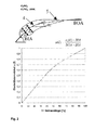
- Fig. 1 shows a side view of an airfoil 1 with swept course of the leading edge 2 of a blade of the compressor of a gas turbine engine. A plurality of sectional planes distributed over the blade height "h" can be seen. According to the skeleton line 4 (FIG. Fig. 2 ) with in each reference point on both sides of the same material thickness "d" is defined by threading the corresponding blade profile sections 5 in the cutting planes 3, the shape of the airfoil 1.
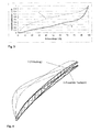
- Fig. 4 are - each with the corresponding schematic pressure load - two blade profile cuts 5 in the near-gap region facing each other, namely of a blade according to the prior art (zigzag line hatching) and of a blade according to the invention (slash-hatching).
- the indicated pressure load is substantially uniform in the blade according to the invention and has the shape of a triangle in the blade according to the prior art, which leads to flow disturbances and losses.
Landscapes
- Engineering & Computer Science (AREA)
- Mechanical Engineering (AREA)
- General Engineering & Computer Science (AREA)
- Physics & Mathematics (AREA)
- Fluid Mechanics (AREA)
- Structures Of Non-Positive Displacement Pumps (AREA)
- Turbine Rotor Nozzle Sealing (AREA)
Applications Claiming Priority (1)
| Application Number | Priority Date | Filing Date | Title |
|---|---|---|---|
| DE102006055869A DE102006055869A1 (de) | 2006-11-23 | 2006-11-23 | Schaufelblattdesign für die Lauf- und Leitschaufeln einer Turbomaschine |
Publications (3)
| Publication Number | Publication Date |
|---|---|
| EP1927724A2 true EP1927724A2 (fr) | 2008-06-04 |
| EP1927724A3 EP1927724A3 (fr) | 2009-05-20 |
| EP1927724B1 EP1927724B1 (fr) | 2015-09-09 |
Family
ID=38904754
Family Applications (1)
| Application Number | Title | Priority Date | Filing Date |
|---|---|---|---|
| EP07120051.3A Not-in-force EP1927724B1 (fr) | 2006-11-23 | 2007-11-06 | Profil d'aube |
Country Status (3)
| Country | Link |
|---|---|
| US (1) | US8152473B2 (fr) |
| EP (1) | EP1927724B1 (fr) |
| DE (1) | DE102006055869A1 (fr) |
Cited By (5)
| Publication number | Priority date | Publication date | Assignee | Title |
|---|---|---|---|---|
| WO2013178914A1 (fr) * | 2012-05-31 | 2013-12-05 | Snecma | Aube de soufflante pour turboreacteur d'avion a profil cambre en sections de pied |
| EP2275643A3 (fr) * | 2009-07-17 | 2017-10-04 | Rolls-Royce Deutschland Ltd & Co KG | Aube de moteur dotée d'une charge de rebords avant surélevée |
| EP2921648B1 (fr) | 2014-03-20 | 2018-12-26 | Ansaldo Energia Switzerland AG | Aube de turbine à gaz avec bord d'attaque et bord de fuite courbé |
| EP3730801A4 (fr) * | 2017-12-20 | 2021-05-05 | Ihi Corporation | Ventilateur et aube de stator de compresseur |
| EP3839212A1 (fr) * | 2019-12-20 | 2021-06-23 | MTU Aero Engines AG | Aube pour une turbomachine |
Families Citing this family (43)
| Publication number | Priority date | Publication date | Assignee | Title |
|---|---|---|---|---|
| US8523531B2 (en) * | 2009-12-23 | 2013-09-03 | Alstom Technology Ltd | Airfoil for a compressor blade |
| US9291059B2 (en) * | 2009-12-23 | 2016-03-22 | Alstom Technology Ltd. | Airfoil for a compressor blade |
| DE102010009615B4 (de) | 2010-02-27 | 2016-11-17 | MTU Aero Engines AG | Schaufelblatt mit gefädelten Profilschnitten |
| DE102010027588A1 (de) * | 2010-07-19 | 2012-01-19 | Rolls-Royce Deutschland Ltd & Co Kg | Fan-Nachleitradschaufel eines Turbofantriebwerks |
| CN102373971B (zh) * | 2010-08-11 | 2014-06-04 | 中国科学院工程热物理研究所 | 轴流透平与单侧径向排汽/气系统一体化气动设计方法 |
| DE102014200644B4 (de) * | 2014-01-16 | 2017-03-02 | MTU Aero Engines AG | Strangprofil und Verfahren zur Herstellung einer Schaufel eines Nachleitrads, Schaufel eines Nachleitrads, Nachleitrad und Turbomaschine mit solch einem Nachleitrad |
| WO2015175043A2 (fr) | 2014-02-19 | 2015-11-19 | United Technologies Corporation | Profil aérodynamique de moteur à turbine à gaz |
| EP3108101B1 (fr) | 2014-02-19 | 2022-04-20 | Raytheon Technologies Corporation | Profil aérodynamique de moteur à turbine à gaz |
| WO2015175052A2 (fr) | 2014-02-19 | 2015-11-19 | United Technologies Corporation | Profil aérodynamique de turbine à gaz |
| WO2015126941A1 (fr) | 2014-02-19 | 2015-08-27 | United Technologies Corporation | Profil aérodynamique de moteur à turbine à gaz |
| WO2015175044A2 (fr) * | 2014-02-19 | 2015-11-19 | United Technologies Corporation | Profil aérodynamique de moteur à turbine à gaz |
| US10570915B2 (en) | 2014-02-19 | 2020-02-25 | United Technologies Corporation | Gas turbine engine airfoil |
| EP3108120B1 (fr) | 2014-02-19 | 2021-03-31 | Raytheon Technologies Corporation | Moteur à turbine à gaz ayant une architecture à engrenages et une structure à aube fixe spécifique |
| EP3575551B1 (fr) | 2014-02-19 | 2021-10-27 | Raytheon Technologies Corporation | Surface portante de moteur à turbine à gaz |
| EP3108105B1 (fr) | 2014-02-19 | 2021-05-12 | Raytheon Technologies Corporation | Surface portante pour turbine à gaz |
| US9567858B2 (en) | 2014-02-19 | 2017-02-14 | United Technologies Corporation | Gas turbine engine airfoil |
| EP3108123B1 (fr) | 2014-02-19 | 2023-10-04 | Raytheon Technologies Corporation | Moteur à double flux à engrenage avec aubes de compresseur basse pression |
| US10570916B2 (en) | 2014-02-19 | 2020-02-25 | United Technologies Corporation | Gas turbine engine airfoil |
| WO2015175073A2 (fr) | 2014-02-19 | 2015-11-19 | United Technologies Corporation | Surface portante de moteur à turbine à gaz |
| US10465702B2 (en) | 2014-02-19 | 2019-11-05 | United Technologies Corporation | Gas turbine engine airfoil |
| EP3108103B1 (fr) | 2014-02-19 | 2023-09-27 | Raytheon Technologies Corporation | Aube de soufflante pour moteur à turbine à gaz |
| US9140127B2 (en) | 2014-02-19 | 2015-09-22 | United Technologies Corporation | Gas turbine engine airfoil |
| WO2015126454A1 (fr) | 2014-02-19 | 2015-08-27 | United Technologies Corporation | Surface portante de moteur à turbine à gaz |
| US10495106B2 (en) | 2014-02-19 | 2019-12-03 | United Technologies Corporation | Gas turbine engine airfoil |
| US10584715B2 (en) | 2014-02-19 | 2020-03-10 | United Technologies Corporation | Gas turbine engine airfoil |
| EP3108106B1 (fr) | 2014-02-19 | 2022-05-04 | Raytheon Technologies Corporation | Pale de moteur à turbine à gaz |
| EP3108100B1 (fr) | 2014-02-19 | 2021-04-14 | Raytheon Technologies Corporation | Pale de soufflante de moteur à turbine à gaz |
| EP3985226B1 (fr) | 2014-02-19 | 2024-12-25 | RTX Corporation | Profil d'aube pour moteur à turbine à gaz |
| CN105221193B (zh) * | 2014-06-12 | 2017-01-25 | 中国科学院工程热物理研究所 | 一种轴流透平与单侧径向排汽/气系统设计方法 |
| JP6468414B2 (ja) | 2014-08-12 | 2019-02-13 | 株式会社Ihi | 圧縮機静翼、軸流圧縮機、及びガスタービン |
| JP6421091B2 (ja) * | 2015-07-30 | 2018-11-07 | 三菱日立パワーシステムズ株式会社 | 軸流圧縮機、それを備えたガスタービン、及び軸流圧縮機の静翼 |
| DE102016115868A1 (de) * | 2016-08-26 | 2018-03-01 | Rolls-Royce Deutschland Ltd & Co Kg | Strömungsarbeitsmaschine mit hohem Ausnutzungsgrad |
| EP3633207A4 (fr) * | 2017-05-24 | 2021-06-23 | IHI Corporation | Pale pour ventilateur et compresseur |
| US10760587B2 (en) | 2017-06-06 | 2020-09-01 | Elliott Company | Extended sculpted twisted return channel vane arrangement |
| CN114867944B (zh) | 2019-12-09 | 2024-01-26 | Lg电子株式会社 | 送风机 |
| US11286779B2 (en) * | 2020-06-03 | 2022-03-29 | Honeywell International Inc. | Characteristic distribution for rotor blade of booster rotor |
| CN112855284B (zh) * | 2021-01-18 | 2022-11-08 | 西北工业大学 | 一种低压涡轮静子叶片波浪前缘的构造方法 |
| CN114973902B (zh) * | 2022-04-14 | 2023-06-23 | 西北工业大学 | 一种教学用航空发动机低压涡轮模型及装配方法 |
| CN115288907A (zh) * | 2022-08-18 | 2022-11-04 | 南通河海大学海洋与近海工程研究院 | 一种低转速环境友好型轴流式水轮机 |
| GB202216273D0 (en) * | 2022-11-02 | 2022-12-14 | Rolls Royce Plc | Fan blade for a gas turbine engine |
| US12366176B2 (en) | 2023-08-28 | 2025-07-22 | General Electric Company | Rotor system for a turbine engine |
| BE1032189B1 (fr) | 2023-12-01 | 2025-06-30 | Safran Aero Boosters | Aube pour compresseur de turbomachine d'aeronef, compresseur, turbomachine |
| US12509988B2 (en) | 2024-06-14 | 2025-12-30 | Pratt & Whitney Canada Corp. | Turbine engine airfoil |
Family Cites Families (15)
| Publication number | Priority date | Publication date | Assignee | Title |
|---|---|---|---|---|
| US4431376A (en) * | 1980-10-27 | 1984-02-14 | United Technologies Corporation | Airfoil shape for arrays of airfoils |
| DE3201436C1 (de) | 1982-01-19 | 1983-04-21 | Kraftwerk Union AG, 4330 Mülheim | Turbomaschinenschaufel |
| DE3441115C1 (de) * | 1984-11-10 | 1986-01-30 | Daimler-Benz Ag, 7000 Stuttgart | Laufrad fuer eine Gasturbine |
| GB9119846D0 (en) | 1991-09-17 | 1991-10-30 | Rolls Royce Plc | Aerofoil members for gas turbine engines and method of making the same |
| JP3082378B2 (ja) | 1991-12-20 | 2000-08-28 | 株式会社デンソー | 送風ファン |
| DE4344189C1 (de) * | 1993-12-23 | 1995-08-03 | Mtu Muenchen Gmbh | Axial-Schaufelgitter mit gepfeilten Schaufelvorderkanten |
| DE69820853T2 (de) * | 1998-03-23 | 2004-11-18 | Spal S.R.L., Correggio | Axiallüfter |
| GB0003676D0 (en) | 2000-02-17 | 2000-04-05 | Abb Alstom Power Nv | Aerofoils |
| JP4557397B2 (ja) * | 2000-09-05 | 2010-10-06 | 本田技研工業株式会社 | 翼形状設計方法および情報媒体 |
| US6755612B2 (en) * | 2002-09-03 | 2004-06-29 | Rolls-Royce Plc | Guide vane for a gas turbine engine |
| US7547186B2 (en) * | 2004-09-28 | 2009-06-16 | Honeywell International Inc. | Nonlinearly stacked low noise turbofan stator |
| DE102004054752A1 (de) * | 2004-11-12 | 2006-05-18 | Rolls-Royce Deutschland Ltd & Co Kg | Schaufel einer Strömungsarbeitsmaschine mit erweiterter Randprofiltiefe |
| DE102005042115A1 (de) * | 2005-09-05 | 2007-03-08 | Rolls-Royce Deutschland Ltd & Co Kg | Schaufel einer Strömungsarbeitsmaschine mit blockweise definierter Profilskelettlinie |
| DE112006002658B4 (de) * | 2005-10-11 | 2021-01-07 | General Electric Technology Gmbh | Turbomaschinenschaufel |
| DE102005060699A1 (de) * | 2005-12-19 | 2007-06-21 | Rolls-Royce Deutschland Ltd & Co Kg | Strömungsarbeitsmaschine mit Verstellstator |
-
2006
- 2006-11-23 DE DE102006055869A patent/DE102006055869A1/de not_active Withdrawn
-
2007
- 2007-11-06 EP EP07120051.3A patent/EP1927724B1/fr not_active Not-in-force
- 2007-11-21 US US11/984,826 patent/US8152473B2/en active Active
Cited By (10)
| Publication number | Priority date | Publication date | Assignee | Title |
|---|---|---|---|---|
| EP2275643A3 (fr) * | 2009-07-17 | 2017-10-04 | Rolls-Royce Deutschland Ltd & Co KG | Aube de moteur dotée d'une charge de rebords avant surélevée |
| WO2013178914A1 (fr) * | 2012-05-31 | 2013-12-05 | Snecma | Aube de soufflante pour turboreacteur d'avion a profil cambre en sections de pied |
| FR2991373A1 (fr) * | 2012-05-31 | 2013-12-06 | Snecma | Aube de soufflante pour turboreacteur d'avion a profil cambre en sections de pied |
| US11333164B2 (en) | 2012-05-31 | 2022-05-17 | Safran Aircraft Engines | Airplane turbojet fan blade of cambered profile in its root sections |
| EP2921648B1 (fr) | 2014-03-20 | 2018-12-26 | Ansaldo Energia Switzerland AG | Aube de turbine à gaz avec bord d'attaque et bord de fuite courbé |
| EP3730801A4 (fr) * | 2017-12-20 | 2021-05-05 | Ihi Corporation | Ventilateur et aube de stator de compresseur |
| US11203945B2 (en) | 2017-12-20 | 2021-12-21 | Ihi Corporation | Stator vane of fan or compressor |
| EP3839212A1 (fr) * | 2019-12-20 | 2021-06-23 | MTU Aero Engines AG | Aube pour une turbomachine |
| WO2021121458A1 (fr) * | 2019-12-20 | 2021-06-24 | MTU Aero Engines AG | Aube directrice destinée à une turbomachine |
| US12180855B2 (en) | 2019-12-20 | 2024-12-31 | MTU Aero Engines AG | Rotor blade for a turbomachine |
Also Published As
| Publication number | Publication date |
|---|---|
| US20090226322A1 (en) | 2009-09-10 |
| US8152473B2 (en) | 2012-04-10 |
| EP1927724B1 (fr) | 2015-09-09 |
| DE102006055869A1 (de) | 2008-05-29 |
| EP1927724A3 (fr) | 2009-05-20 |
Similar Documents
| Publication | Publication Date | Title |
|---|---|---|
| EP1927724B1 (fr) | Profil d'aube | |
| EP1671030B1 (fr) | Pale de rotor pour une éolienne | |
| EP3762587B1 (fr) | Pale d'aube pour une aube de turbine | |
| DE60037170T2 (de) | Leitschaufel | |
| DE69718229T2 (de) | Spitzendichtung für Turbinenlaufschaufeln | |
| DE69105837T2 (de) | Gekühlte Turbinenschaufel. | |
| DE3045224C2 (fr) | ||
| DE3530769C2 (de) | Schaufel für ein Gasturbinentriebwerk | |
| EP2275643B1 (fr) | Aube de moteur dotée d'une charge de rebords avant surélevée | |
| EP2299124A1 (fr) | Aube de rotor pour un compresseur axial | |
| EP1923567A2 (fr) | Pale d'éolienne et éolienne | |
| DE69012275T2 (de) | Laufschaufel für Axialströmungsmaschine. | |
| DE2650433B2 (de) | Laufschaufel einer axialen Strömungsmaschine | |
| WO2000057029A1 (fr) | Aube de turbine | |
| EP0528138A1 (fr) | Anneau d'aube de turbine axiale | |
| EP0825332A1 (fr) | Aube refroidissable | |
| EP2226511A2 (fr) | Turbomachine de travail dotée d'une arrivée de fluide | |
| DE102005042115A1 (de) | Schaufel einer Strömungsarbeitsmaschine mit blockweise definierter Profilskelettlinie | |
| EP1766192B1 (fr) | Roue a aubes d'une turbine presentant une aube et au moins un canal refrigerant | |
| EP0937862A2 (fr) | Forme pour les aubes des turbines axiales | |
| EP3039246B1 (fr) | Aube de turbine | |
| DE60206292T2 (de) | Geschwindigkeitsbegrenzer für turbinen im lastfreien betrieb | |
| DE102006048685A1 (de) | Turbinenschaufel einer Gasturbine | |
| EP1865148A2 (fr) | Machine de traitement des écoulements dotée de rotors de distribution d'énergie supérieure spécifique | |
| DE3306298A1 (de) | Statorschaufelaufbau fuer gasturbinentriebwerke |
Legal Events
| Date | Code | Title | Description |
|---|---|---|---|
| PUAI | Public reference made under article 153(3) epc to a published international application that has entered the european phase |
Free format text: ORIGINAL CODE: 0009012 |
|
| AK | Designated contracting states |
Kind code of ref document: A2 Designated state(s): AT BE BG CH CY CZ DE DK EE ES FI FR GB GR HU IE IS IT LI LT LU LV MC MT NL PL PT RO SE SI SK TR |
|
| AX | Request for extension of the european patent |
Extension state: AL BA HR MK RS |
|
| PUAL | Search report despatched |
Free format text: ORIGINAL CODE: 0009013 |
|
| AK | Designated contracting states |
Kind code of ref document: A3 Designated state(s): AT BE BG CH CY CZ DE DK EE ES FI FR GB GR HU IE IS IT LI LT LU LV MC MT NL PL PT RO SE SI SK TR |
|
| AX | Request for extension of the european patent |
Extension state: AL BA HR MK RS |
|
| 17P | Request for examination filed |
Effective date: 20090721 |
|
| 17Q | First examination report despatched |
Effective date: 20090820 |
|
| AKX | Designation fees paid |
Designated state(s): DE FR GB |
|
| GRAP | Despatch of communication of intention to grant a patent |
Free format text: ORIGINAL CODE: EPIDOSNIGR1 |
|
| INTG | Intention to grant announced |
Effective date: 20150123 |
|
| GRAS | Grant fee paid |
Free format text: ORIGINAL CODE: EPIDOSNIGR3 |
|
| GRAA | (expected) grant |
Free format text: ORIGINAL CODE: 0009210 |
|
| AK | Designated contracting states |
Kind code of ref document: B1 Designated state(s): DE FR GB |
|
| REG | Reference to a national code |
Ref country code: GB Ref legal event code: FG4D Free format text: NOT ENGLISH |
|
| REG | Reference to a national code |
Ref country code: DE Ref legal event code: R096 Ref document number: 502007014198 Country of ref document: DE |
|
| REG | Reference to a national code |
Ref country code: FR Ref legal event code: PLFP Year of fee payment: 9 |
|
| REG | Reference to a national code |
Ref country code: DE Ref legal event code: R097 Ref document number: 502007014198 Country of ref document: DE |
|
| PLBE | No opposition filed within time limit |
Free format text: ORIGINAL CODE: 0009261 |
|
| STAA | Information on the status of an ep patent application or granted ep patent |
Free format text: STATUS: NO OPPOSITION FILED WITHIN TIME LIMIT |
|
| 26N | No opposition filed |
Effective date: 20160610 |
|
| REG | Reference to a national code |
Ref country code: FR Ref legal event code: PLFP Year of fee payment: 10 |
|
| REG | Reference to a national code |
Ref country code: FR Ref legal event code: PLFP Year of fee payment: 11 |
|
| PGFP | Annual fee paid to national office [announced via postgrant information from national office to epo] |
Ref country code: DE Payment date: 20191127 Year of fee payment: 13 |
|
| PGFP | Annual fee paid to national office [announced via postgrant information from national office to epo] |
Ref country code: FR Payment date: 20191125 Year of fee payment: 13 |
|
| PGFP | Annual fee paid to national office [announced via postgrant information from national office to epo] |
Ref country code: GB Payment date: 20191127 Year of fee payment: 13 |
|
| REG | Reference to a national code |
Ref country code: DE Ref legal event code: R119 Ref document number: 502007014198 Country of ref document: DE |
|
| GBPC | Gb: european patent ceased through non-payment of renewal fee |
Effective date: 20201106 |
|
| PG25 | Lapsed in a contracting state [announced via postgrant information from national office to epo] |
Ref country code: FR Free format text: LAPSE BECAUSE OF NON-PAYMENT OF DUE FEES Effective date: 20201130 |
|
| PG25 | Lapsed in a contracting state [announced via postgrant information from national office to epo] |
Ref country code: GB Free format text: LAPSE BECAUSE OF NON-PAYMENT OF DUE FEES Effective date: 20201106 Ref country code: DE Free format text: LAPSE BECAUSE OF NON-PAYMENT OF DUE FEES Effective date: 20210601 |