EP1927833A2 - Dispositif de mesure de la température d'un fluide - Google Patents
Dispositif de mesure de la température d'un fluide Download PDFInfo
- Publication number
- EP1927833A2 EP1927833A2 EP07254297A EP07254297A EP1927833A2 EP 1927833 A2 EP1927833 A2 EP 1927833A2 EP 07254297 A EP07254297 A EP 07254297A EP 07254297 A EP07254297 A EP 07254297A EP 1927833 A2 EP1927833 A2 EP 1927833A2
- Authority
- EP
- European Patent Office
- Prior art keywords
- temperature measuring
- measuring device
- fluid flow
- component
- temperature
- Prior art date
- Legal status (The legal status is an assumption and is not a legal conclusion. Google has not performed a legal analysis and makes no representation as to the accuracy of the status listed.)
- Granted
Links
Images
Classifications
-
- G—PHYSICS
- G01—MEASURING; TESTING
- G01K—MEASURING TEMPERATURE; MEASURING QUANTITY OF HEAT; THERMALLY-SENSITIVE ELEMENTS NOT OTHERWISE PROVIDED FOR
- G01K1/00—Details of thermometers not specially adapted for particular types of thermometer
- G01K1/14—Supports; Fastening devices; Arrangements for mounting thermometers in particular locations
-
- C—CHEMISTRY; METALLURGY
- C09—DYES; PAINTS; POLISHES; NATURAL RESINS; ADHESIVES; COMPOSITIONS NOT OTHERWISE PROVIDED FOR; APPLICATIONS OF MATERIALS NOT OTHERWISE PROVIDED FOR
- C09D—COATING COMPOSITIONS, e.g. PAINTS, VARNISHES OR LACQUERS; FILLING PASTES; CHEMICAL PAINT OR INK REMOVERS; INKS; CORRECTING FLUIDS; WOODSTAINS; PASTES OR SOLIDS FOR COLOURING OR PRINTING; USE OF MATERIALS THEREFOR
- C09D5/00—Coating compositions, e.g. paints, varnishes or lacquers, characterised by their physical nature or the effects produced; Filling pastes
- C09D5/26—Thermosensitive paints
-
- F—MECHANICAL ENGINEERING; LIGHTING; HEATING; WEAPONS; BLASTING
- F01—MACHINES OR ENGINES IN GENERAL; ENGINE PLANTS IN GENERAL; STEAM ENGINES
- F01D—NON-POSITIVE DISPLACEMENT MACHINES OR ENGINES, e.g. STEAM TURBINES
- F01D21/00—Shutting-down of machines or engines, e.g. in emergency; Regulating, controlling, or safety means not otherwise provided for
- F01D21/003—Arrangements for testing or measuring
-
- G—PHYSICS
- G01—MEASURING; TESTING
- G01K—MEASURING TEMPERATURE; MEASURING QUANTITY OF HEAT; THERMALLY-SENSITIVE ELEMENTS NOT OTHERWISE PROVIDED FOR
- G01K11/00—Measuring temperature based upon physical or chemical changes not covered by groups G01K3/00, G01K5/00, G01K7/00 or G01K9/00
- G01K11/06—Measuring temperature based upon physical or chemical changes not covered by groups G01K3/00, G01K5/00, G01K7/00 or G01K9/00 using melting, freezing, or softening
-
- G—PHYSICS
- G01—MEASURING; TESTING
- G01K—MEASURING TEMPERATURE; MEASURING QUANTITY OF HEAT; THERMALLY-SENSITIVE ELEMENTS NOT OTHERWISE PROVIDED FOR
- G01K11/00—Measuring temperature based upon physical or chemical changes not covered by groups G01K3/00, G01K5/00, G01K7/00 or G01K9/00
- G01K11/12—Measuring temperature based upon physical or chemical changes not covered by groups G01K3/00, G01K5/00, G01K7/00 or G01K9/00 using changes in colour, translucency or reflectance
-
- G—PHYSICS
- G01—MEASURING; TESTING
- G01K—MEASURING TEMPERATURE; MEASURING QUANTITY OF HEAT; THERMALLY-SENSITIVE ELEMENTS NOT OTHERWISE PROVIDED FOR
- G01K13/00—Thermometers specially adapted for specific purposes
- G01K13/02—Thermometers specially adapted for specific purposes for measuring temperature of moving fluids or granular materials capable of flow
- G01K13/024—Thermometers specially adapted for specific purposes for measuring temperature of moving fluids or granular materials capable of flow of moving gases
-
- F—MECHANICAL ENGINEERING; LIGHTING; HEATING; WEAPONS; BLASTING
- F05—INDEXING SCHEMES RELATING TO ENGINES OR PUMPS IN VARIOUS SUBCLASSES OF CLASSES F01-F04
- F05D—INDEXING SCHEME FOR ASPECTS RELATING TO NON-POSITIVE-DISPLACEMENT MACHINES OR ENGINES, GAS-TURBINES OR JET-PROPULSION PLANTS
- F05D2260/00—Function
- F05D2260/80—Diagnostics
Definitions
- the present invention relates to a temperature measurement device for measuring the temperature of air, particularly but not exclusively, in a conduit in a gas turbine engine.
- thermocouples for example thermocouples, thin film gauges, hot wires and thermopiles and each may be calibrated to give an indication of a fluid's temperature when applied to a wall of the fluid conduit.
- all these prior art devices suffer from installation and signal conditioning shortfalls in addition to robustness limits especially if used in a gas turbine engine environment.
- a further problem is that these devices measure the temperature of the component rather than the temperature of the direct temperature of the fluid.
- the thermal inertia of the component means that rapid changes of the fluid's temperature will not be measured.
- the expense is also a major consideration. As a result incomplete temperature measurement of a conduit or system is the common.
- system calibration, signal conditioning and physically routing the measurement data is also time consuming and therefore expensive.
- a fluid flow temperature measuring device for a fluid passing a component, characterised in that the device comprises a substrate, of lower thermal capacity than the component, having applied thereto a temperature recording media, the device is attached to and spaced apart from the component and is in the fluid flow.
- two different temperature recording media are applied to the substrate.
- the temperature recording media is any one of the group comprising a wax based thermal tab and a thermal paint.
- the temperature recording media are placed on different sides of the substrate.
- the substrate has a lower thermal capacity than the component.
- the substrate is 0.25 mm in thickness, but may be less than 2 mm in thickness.
- the substrate is metallic.
- a radiation shield is positioned between the substrate and the component.
- At least one temperature measuring device is attached to the radiation shield.
- the radiation shield is a low emissivity coating applied to the component.
- the radiation shield is a low emissivity coating applied to one side of the shim.
- a ducted fan gas turbine engine generally indicated at 10 has a principal and rotational axis 11.
- the engine 10 comprises, in axial flow series, an air intake 11, a propulsive fan 12, an intermediate pressure compressor 13, a high-pressure compressor 14, combustion equipment 15, a high-pressure turbine 16, and intermediate pressure turbine 17, a low-pressure turbine 18 and a core exhaust nozzle 19.
- a nacelle 21 generally surrounds the engine 10 and defines the intake 11, a bypass duct 22 and an exhaust nozzle 23.
- the gas turbine engine 10 works in the conventional manner so that air entering the intake 11 is accelerated by the fan 12 to produce two air flows: a first airflow A into the intermediate pressure compressor 13 and a second airflow B which passes through a bypass duct 22 to provide propulsive thrust.
- the intermediate pressure compressor 13 compresses the airflow A directed into it before delivering that air to the high pressure compressor 14 where further compression takes place.
- the compressed air exhausted from the high-pressure compressor 14 is directed into the combustion equipment 15 where it is mixed with fuel and the mixture combusted.
- the resultant hot combustion products then expand through, and thereby drive the high, intermediate and low-pressure turbines 16, 17, 18 before being exhausted through the nozzle 19 to provide additional propulsive thrust.
- the high, intermediate and low-pressure turbines 16, 17, 18 respectively drive the high and intermediate pressure compressors 14, 13 and the fan 12 by suitable interconnecting shafts.
- the fan 12 is circumferentially surrounded by a structural member in the form of a fan casing 24, which is supported by an annular array of outlet guide vanes 25.
- the core of the engine comprises the compressors 13, 14, combustor 15 and turbines 16, 17, 18 and is surrounded by an inner casing 26 and outer casing 27, which define a space therebetween.
- Various engine accessories are housed between the inner and outer casings 26, 27 and there is a requirement to ventilate this space, otherwise known as a fire zone. Ventilation air is ducted through the fire zone by conventional means not shown, but produces a flow of air generally passing in the direction of arrow C. The ventilation air also provides cooling to the engine casings and accessories.
- An example application of the present invention is monitoring the temperature of the ventilation air flowing through the fire zone so that suitable quantities can be provided and directed therearound.
- the required minimum amount of air can be set so that fixed ducting can be designed to provide minimum amounts of air.
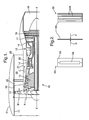
- a temperature measuring device 30 in accordance with the present invention, comprises recording media 32, 34 applied to a substrate of very low thermal capacity.
- a thin stainless steel shim 36 is used. This arrangement ensures very fast temperature change and therefore is capable of recording the temperature of a fluid, particularly gases.
- a preferred embodiment employs, on one side of the shim 36, a wax based thermal tab 32a-32g and on the other side, an array of thermal paints 34a-34e.
- the thermal tab 32 comprises an array of wax elements 32a-32g each of which has an indicative melt point.
- the melt points are 40, 70, 100, 130, 160, 200, 225, 260°C.
- the thermal paints 34a-34e have colour change points of 120, 165, 210, 270 and 350°C and broadly cover the temperature range of the thermal tab 32.
- the thermal paints 34a-34e act as a cross check to ensure the thermal tab 32 is operating correctly as contamination from oil, for example, is a known occurrence.
- thermal tab 32 and thermal paint 34 may be placed on the same side of the shim 36.
- the temperature measuring device 30 of the present invention is an independent device not connected by wires such as with a thermocouple.
- other independent recording media may be substituted for either the thermal tab 32 or the stripes of thermal paint 34.
- the substrate or shim has a very low thermal capacity and is particularly thin although this depends on the material used.
- a suitable thickness is 0.25 mm.
- a slightly thicker shim 36 may be used, as its density and thermal inertia is less than steel.
- the low thermal capacity ensures that the recording media 32, 34 are almost instantly subject to changes in the thermal flux of the air flow C, rather than the shim itself or worse the component/casing.
- the term 'low thermal capacity' refers to the shim 36 having a lower thermal capacity than the component 26 it is attached to. However, it is preferable for the shim's thermal capacity to be as low as possible.
- the suitable plan size of the substrate or shim can be chosen to suit the required task and in this exemplary embodiment, the preferred size is approximately 75mm x 25mm.
- the low weight of the device 30 allows it to be attached by wires 38 threaded through holes 40 at either end of the shim 36 to any suitable part of the engine structure, in this case bolts 39 on a flange 41 joining two casings.
- the device 30 is spaced apart from the component or casing 26. Therefore conductive heat from the component is not passed into the device 30. Thus the temperature measuring arrangement does not require calibration relative to its application and more precise temperatures of the fluid C are recorded.
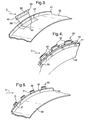
- a series of temperature measuring devices 30 are attached to a radiation shield 42, such that the radiation shield is between the device and the hot casing 24, 31.
- the shim portion 36 is held away from the shield 42 by legs 31 extending from the shim 36 to the shield 42.
- This radiation shield 42 may be formed from a variety of shapes to fit the particular application. In this example air temperature readings are required around the circumference of the casing 26 so the shield 42 is an annular strip, however, it may also be made from segments joined together to surround the casing 26.
- a low emissivity coating 44 may be applied to the flange and casing adjacent the temperature measuring device 30 (see figure 3 ).
- the emissivity coating 44 is defined as low relative to the component 26 itself, however, the skilled person would appreciate that the coating should have as low an emissivity as practicable.
- the temperature measuring device 30 comprises zigzags of shims 36 and portions 35 connected by legs 35.
- the portions 35 are in contact with the casing and may be temporarily attached via spot welding or adhesive for example or may be annular and held in place by an interference fit.
- the thermal tab 32 and paints 34 are on opposing sides D and E, however, thermal indicating media 32, 34 may be placed on side D and a low emissivity coating 44 may be applied to side E facing the casing.
- the temperature measuring device 30 is particularly suitable for finding leaks within the fire zone as these leaks may only be apparent at transient conditions and therefore short time periods. Thermal recording media applied to the casing itself would not be suitable for detecting these types of temperature fluxes.
- temperature measuring device 30 is not restricted to application in a gas turbine engine and the skilled person would readily appreciate other applications where monitoring the temperature of any fluid is required.
- the advantages of the temperature measuring device 30 are: low cost, ease of installation obviating the need for expensive routing and readout equipment and high integrity due to the use of established temperature indicating techniques.
Landscapes
- Physics & Mathematics (AREA)
- General Physics & Mathematics (AREA)
- Engineering & Computer Science (AREA)
- Chemical & Material Sciences (AREA)
- Life Sciences & Earth Sciences (AREA)
- Materials Engineering (AREA)
- Wood Science & Technology (AREA)
- Organic Chemistry (AREA)
- Mechanical Engineering (AREA)
- General Engineering & Computer Science (AREA)
- Measuring Temperature Or Quantity Of Heat (AREA)
Applications Claiming Priority (1)
| Application Number | Priority Date | Filing Date | Title |
|---|---|---|---|
| GBGB0624002.2A GB0624002D0 (en) | 2006-12-01 | 2006-12-01 | Fluid temperature measurement device |
Publications (3)
| Publication Number | Publication Date |
|---|---|
| EP1927833A2 true EP1927833A2 (fr) | 2008-06-04 |
| EP1927833A3 EP1927833A3 (fr) | 2009-08-26 |
| EP1927833B1 EP1927833B1 (fr) | 2017-08-30 |
Family
ID=37671667
Family Applications (1)
| Application Number | Title | Priority Date | Filing Date |
|---|---|---|---|
| EP07254297.0A Ceased EP1927833B1 (fr) | 2006-12-01 | 2007-10-30 | Dispositif de mesure de la température d'un fluide |
Country Status (3)
| Country | Link |
|---|---|
| US (1) | US7819578B2 (fr) |
| EP (1) | EP1927833B1 (fr) |
| GB (1) | GB0624002D0 (fr) |
Cited By (5)
| Publication number | Priority date | Publication date | Assignee | Title |
|---|---|---|---|---|
| DE102009034796A1 (de) * | 2009-07-25 | 2011-02-24 | Man Diesel & Turbo Se | Verfahren zum Installieren von Funktionsüberwachungsmitteln in einer Strömungsmaschinenanlage |
| CN106233109A (zh) * | 2014-04-23 | 2016-12-14 | 西门子能源有限公司 | 确定用于燃气涡轮发动机的声学收发器的波导温度的方法 |
| EP3315931A1 (fr) * | 2016-10-25 | 2018-05-02 | Rolls-Royce Deutschland Ltd & Co KG | Procédé de détermination de la température dans un canal d'écoulement d'une turbine à gaz et dispositif de mesure |
| GB2557460A (en) * | 2016-11-29 | 2018-06-20 | Airbus Operations Sas | Protective system of a thermocouple positioned in a compartment of an aircraft engine |
| EP3561233A1 (fr) * | 2018-04-25 | 2019-10-30 | Siemens Aktiengesellschaft | Composant refroidi intérieurement pour une turbomachine, disque de rotor et procédé pour mésurer une temperature associés |
Families Citing this family (8)
| Publication number | Priority date | Publication date | Assignee | Title |
|---|---|---|---|---|
| JP2008062568A (ja) * | 2006-09-08 | 2008-03-21 | Seiko Epson Corp | 液体噴射ヘッドのアライメント治具及びアライメント装置 |
| US8839662B2 (en) | 2011-06-27 | 2014-09-23 | United Technologies Corporation | Station probe for gas turbine engines |
| US8599009B2 (en) | 2011-08-16 | 2013-12-03 | Elwha Llc | Systematic distillation of status data relating to regimen compliance |
| US9630767B2 (en) | 2013-05-14 | 2017-04-25 | Icp Adhesives And Sealants, Inc. | Temperature indicating foam gun nozzles and hoses |
| US9233385B2 (en) * | 2013-05-14 | 2016-01-12 | Fomo Products, Inc. | Temperature indicating foam gun nozzles and hoses |
| RU2017141917A (ru) * | 2015-06-09 | 2019-07-09 | Нуово Пиньоне Текнолоджи Срл | Турбомашинный компонент со средством сигнализации, турбомашина и способ усовершенствования турбомашинного компонента |
| US11002615B2 (en) * | 2019-03-18 | 2021-05-11 | Raytheon Technologies Corporation | Thermochromatic test device for gas turbine engine |
| DE102019124605A1 (de) * | 2019-09-12 | 2021-03-18 | Endress + Hauser Wetzer Gmbh + Co. Kg | Nicht invasives Thermometer |
Family Cites Families (46)
| Publication number | Priority date | Publication date | Assignee | Title |
|---|---|---|---|---|
| US1372554A (en) * | 1919-11-03 | 1921-03-22 | Julius E Kiefer | Thermostatic signal for automobile-radiators |
| US1515222A (en) * | 1921-07-11 | 1924-11-11 | Ruben Samuel | Temperature indicator for internal-combustion engines |
| US2552017A (en) * | 1947-04-26 | 1951-05-08 | Wright Aeronautical Corp | Flowmeter |
| US3059474A (en) * | 1959-09-24 | 1962-10-23 | Gen Dynamics Corp | Temperature indicating device |
| US4019368A (en) * | 1976-01-08 | 1977-04-26 | Navato Jose Miguel Antonio Ros | Pictorial room thermometer |
| US4121763A (en) * | 1977-07-07 | 1978-10-24 | The Garrett Corporation | Fluid temperature transducer |
| US4241868A (en) * | 1978-10-12 | 1980-12-30 | Perkins Jean K | Fluid temperature mixing indicator |
| DE3006603A1 (de) * | 1980-02-22 | 1981-09-03 | Robert Bosch Gmbh, 7000 Stuttgart | Sensoranordnung |
| FR2489511A1 (fr) * | 1980-08-28 | 1982-03-05 | Snecma | Systeme de mesure d'une grandeur d'etat caracteristique d'un fluide en ecoulement |
| GB2092744B (en) | 1981-02-06 | 1984-05-31 | Spirig Ernst | Temperature indicator |
| DE3111948A1 (de) * | 1981-03-26 | 1982-10-07 | Robert Bosch Gmbh, 7000 Stuttgart | Schneller temperatursensor fuer eine brennkraftmaschine |
| DE3327389A1 (de) * | 1983-07-29 | 1985-02-07 | Siemens AG, 1000 Berlin und 8000 München | Temperaturmesssonde |
| JPS60166815A (ja) * | 1984-02-10 | 1985-08-30 | Hitachi Ltd | ガスタ−ビンコンプレツサ翼付着物監視装置 |
| US4630028A (en) * | 1985-04-30 | 1986-12-16 | Borg-Warner Corporation | Pressure-biased, temperature sensor |
| US4978230A (en) * | 1988-04-13 | 1990-12-18 | General Electric Company | Apparatus and method for determining heat transfer coefficient based on testing actual hardware rather than simplistic scale models of such hardware |
| DE4009833C2 (de) * | 1989-03-31 | 1996-09-26 | Aisan Ind | Luftmengenmeßeinrichtung für Ansaugluft |
| US4994792A (en) * | 1989-12-06 | 1991-02-19 | Ziegler Jr Eldon W | Fluid temperature monitoring system |
| US5265959A (en) * | 1992-10-16 | 1993-11-30 | Meltzer Jeffrey N | Temperature sensing apparatus |
| US5380092A (en) * | 1993-10-07 | 1995-01-10 | Alain; George | Fluid temperature indicator |
| JP3146405B2 (ja) * | 1994-04-27 | 2001-03-19 | 日本サーモスタット株式会社 | 温度センサー |
| US5806528A (en) * | 1995-10-05 | 1998-09-15 | Urosurge, Inc. | In-line temperature sensing devices, systems and methods |
| US6321531B1 (en) * | 1996-12-18 | 2001-11-27 | Litex, Inc. | Method and apparatus for using free radicals to reduce pollutants in the exhaust gases from the combustion of a fuel |
| US5879082A (en) * | 1997-02-25 | 1999-03-09 | Sierra Instruments, Inc. | Dual element temperature sensing probe using a mathematical model of heat transfer along the probe and method therefor |
| JP3364115B2 (ja) * | 1997-07-03 | 2003-01-08 | 三菱電機株式会社 | 感熱式流量検出素子 |
| GB2327755A (en) | 1997-07-24 | 1999-02-03 | Dalebrook Supplies Limited | Label with temperature sensor |
| US6023969A (en) * | 1997-09-17 | 2000-02-15 | Feller; Murray F. | Flow modulated mass flow sensor |
| JP3555492B2 (ja) * | 1998-09-22 | 2004-08-18 | 株式会社デンソー | 温度センサ |
| JP3513048B2 (ja) * | 1999-04-13 | 2004-03-31 | 三菱電機株式会社 | 感熱式流量センサおよびその製造方法 |
| JP3557379B2 (ja) * | 2000-01-24 | 2004-08-25 | 株式会社日立製作所 | 空気流量測定装置 |
| US6432287B1 (en) * | 2000-03-01 | 2002-08-13 | Daimlerchrysler Corporation | Exhaust gas temperature sensing on the outside surface of the oxygen sensor |
| US7329389B2 (en) * | 2001-07-16 | 2008-02-12 | Sensor Tech, Inc. | Sensor device and method for qualitative and quantitative analysis of gas phase substances |
| US6564742B2 (en) | 2001-08-03 | 2003-05-20 | Hewlett-Packard Development Company, Llp | Over-temperature warning device |
| US6804622B2 (en) * | 2001-09-04 | 2004-10-12 | General Electric Company | Method and apparatus for non-destructive thermal inspection |
| US20030056584A1 (en) * | 2001-09-27 | 2003-03-27 | Park Tae-Won | Mass flow sensor and measuring apparatus |
| GB2387951B (en) * | 2002-03-05 | 2004-09-08 | Paul Brooksbank | Fire warning sign |
| US6910387B2 (en) * | 2002-09-04 | 2005-06-28 | Endress + Hausser Flowtec Ag | Vortex flow sensor for measuring fluid flow through a flow tube |
| US7582359B2 (en) * | 2002-09-23 | 2009-09-01 | Siemens Energy, Inc. | Apparatus and method of monitoring operating parameters of a gas turbine |
| US7004622B2 (en) * | 2002-11-22 | 2006-02-28 | General Electric Company | Systems and methods for determining conditions of articles and methods of making such systems |
| GB0307466D0 (en) * | 2003-04-01 | 2003-05-07 | Salvage Richard | A heat-sensitive warning device |
| US7192187B2 (en) * | 2003-04-14 | 2007-03-20 | John R Blichmann | In-line thermometer |
| US6974249B1 (en) * | 2004-03-17 | 2005-12-13 | The United States Of America As Represented By The Secretary Of The Air Force | Thermal history sensor |
| DE102004027907A1 (de) * | 2004-06-09 | 2005-12-29 | Emitec Gesellschaft Für Emissionstechnologie Mbh | Regelsystem für eine mobile Verbrennungskraftmaschine |
| JP4789083B2 (ja) * | 2004-07-15 | 2011-10-05 | 株式会社ジークエスト | 温度感知シール |
| US20060227850A1 (en) * | 2005-04-06 | 2006-10-12 | Johnson Clifton R | Slip on bath water thermometer |
| US7841769B2 (en) * | 2007-09-11 | 2010-11-30 | Gm Global Technology Operations, Inc. | Method and apparatus for determining temperature in a gas feedstream |
| GB0717994D0 (en) * | 2007-09-14 | 2007-10-24 | Epiq Nv | Temperature sensor |
-
2006
- 2006-12-01 GB GBGB0624002.2A patent/GB0624002D0/en not_active Ceased
-
2007
- 2007-10-30 EP EP07254297.0A patent/EP1927833B1/fr not_active Ceased
- 2007-11-01 US US11/979,324 patent/US7819578B2/en active Active
Cited By (7)
| Publication number | Priority date | Publication date | Assignee | Title |
|---|---|---|---|---|
| DE102009034796A1 (de) * | 2009-07-25 | 2011-02-24 | Man Diesel & Turbo Se | Verfahren zum Installieren von Funktionsüberwachungsmitteln in einer Strömungsmaschinenanlage |
| CN106233109A (zh) * | 2014-04-23 | 2016-12-14 | 西门子能源有限公司 | 确定用于燃气涡轮发动机的声学收发器的波导温度的方法 |
| CN106233109B (zh) * | 2014-04-23 | 2019-03-12 | 西门子能源有限公司 | 确定用于燃气涡轮发动机的声学收发器的波导温度的方法 |
| EP3315931A1 (fr) * | 2016-10-25 | 2018-05-02 | Rolls-Royce Deutschland Ltd & Co KG | Procédé de détermination de la température dans un canal d'écoulement d'une turbine à gaz et dispositif de mesure |
| US10550273B2 (en) | 2016-10-25 | 2020-02-04 | Rolls-Royce Deutschland Ltd & Co Kg | Method for determining the temperature in a flow channel of a gas turbine and measuring device |
| GB2557460A (en) * | 2016-11-29 | 2018-06-20 | Airbus Operations Sas | Protective system of a thermocouple positioned in a compartment of an aircraft engine |
| EP3561233A1 (fr) * | 2018-04-25 | 2019-10-30 | Siemens Aktiengesellschaft | Composant refroidi intérieurement pour une turbomachine, disque de rotor et procédé pour mésurer une temperature associés |
Also Published As
| Publication number | Publication date |
|---|---|
| GB0624002D0 (en) | 2007-01-10 |
| US20080130708A1 (en) | 2008-06-05 |
| US7819578B2 (en) | 2010-10-26 |
| EP1927833B1 (fr) | 2017-08-30 |
| EP1927833A3 (fr) | 2009-08-26 |
Similar Documents
| Publication | Publication Date | Title |
|---|---|---|
| EP1927833B1 (fr) | Dispositif de mesure de la température d'un fluide | |
| US9243963B2 (en) | Total temperature probe | |
| EP2610599B1 (fr) | Dispositif de détection de température et procédé pour l'assembler | |
| US3348414A (en) | Gas turbine temperature measuring apparatus | |
| EP2492441A2 (fr) | Système pour mesurer les paramètres d'écoulement de fluide dans une turbomachine | |
| EP2818839A2 (fr) | Sonde de thermocouple | |
| US9927307B2 (en) | Probe | |
| US10996140B2 (en) | Gas turbine engine probes and methods of detecting an engine condition | |
| US9207128B2 (en) | Dynamic fiber temperature sensing package and method of assembling the same | |
| JP6505179B2 (ja) | 排気ガス温度検出プローブアセンブリ | |
| KR20010014275A (ko) | 연소 터빈의 베인 또는 블레이드를 위한 고온점 검출 시스템 | |
| US10465553B2 (en) | Sheathing for fluid probe | |
| US20110082662A1 (en) | Method and device for detecting capacity changes in a fluid and turbine | |
| US6742394B1 (en) | Gas turbine combustor hybrid dynamic-static probe | |
| US4440508A (en) | Detector-transducer for sensing temperatures in an engine | |
| US10254180B2 (en) | Exhaust gas temperature sensing probe assembly | |
| US11243119B2 (en) | Protective sleeve for a component of a turbine engine and method of installing the same | |
| JPS6127699B2 (fr) | ||
| EP3712389B1 (fr) | Dispositif de test thermochromatique pour moteur à turbine à gaz | |
| JPH01176922A (ja) | ガスタービンの排気温度検出装置 | |
| Wilson et al. | A robust radial traverse temperature probe for application to a gas turbine HP/IP stage | |
| CN120907498A (zh) | 一种涡轮导向叶片热变形测量装置 | |
| Buehler et al. | High-Temperature Sensors for Army Gas Turbine Engines |
Legal Events
| Date | Code | Title | Description |
|---|---|---|---|
| PUAI | Public reference made under article 153(3) epc to a published international application that has entered the european phase |
Free format text: ORIGINAL CODE: 0009012 |
|
| AK | Designated contracting states |
Kind code of ref document: A2 Designated state(s): AT BE BG CH CY CZ DE DK EE ES FI FR GB GR HU IE IS IT LI LT LU LV MC MT NL PL PT RO SE SI SK TR |
|
| AX | Request for extension of the european patent |
Extension state: AL BA HR MK RS |
|
| PUAL | Search report despatched |
Free format text: ORIGINAL CODE: 0009013 |
|
| AK | Designated contracting states |
Kind code of ref document: A3 Designated state(s): AT BE BG CH CY CZ DE DK EE ES FI FR GB GR HU IE IS IT LI LT LU LV MC MT NL PL PT RO SE SI SK TR |
|
| AX | Request for extension of the european patent |
Extension state: AL BA HR MK RS |
|
| 17P | Request for examination filed |
Effective date: 20090805 |
|
| 17Q | First examination report despatched |
Effective date: 20091008 |
|
| AKX | Designation fees paid |
Designated state(s): DE FR GB |
|
| RAP1 | Party data changed (applicant data changed or rights of an application transferred) |
Owner name: ROLLS-ROYCE PLC |
|
| REG | Reference to a national code |
Ref country code: DE Ref legal event code: R079 Ref document number: 602007052164 Country of ref document: DE Free format text: PREVIOUS MAIN CLASS: G01K0001160000 Ipc: G01K0001140000 |
|
| GRAP | Despatch of communication of intention to grant a patent |
Free format text: ORIGINAL CODE: EPIDOSNIGR1 |
|
| STAA | Information on the status of an ep patent application or granted ep patent |
Free format text: STATUS: GRANT OF PATENT IS INTENDED |
|
| RIC1 | Information provided on ipc code assigned before grant |
Ipc: G01K 13/02 20060101ALI20170517BHEP Ipc: G01K 1/14 20060101AFI20170517BHEP |
|
| INTG | Intention to grant announced |
Effective date: 20170612 |
|
| GRAS | Grant fee paid |
Free format text: ORIGINAL CODE: EPIDOSNIGR3 |
|
| GRAA | (expected) grant |
Free format text: ORIGINAL CODE: 0009210 |
|
| STAA | Information on the status of an ep patent application or granted ep patent |
Free format text: STATUS: THE PATENT HAS BEEN GRANTED |
|
| AK | Designated contracting states |
Kind code of ref document: B1 Designated state(s): DE FR GB |
|
| REG | Reference to a national code |
Ref country code: GB Ref legal event code: FG4D |
|
| REG | Reference to a national code |
Ref country code: DE Ref legal event code: R096 Ref document number: 602007052164 Country of ref document: DE |
|
| REG | Reference to a national code |
Ref country code: FR Ref legal event code: PLFP Year of fee payment: 11 |
|
| REG | Reference to a national code |
Ref country code: DE Ref legal event code: R097 Ref document number: 602007052164 Country of ref document: DE |
|
| PLBE | No opposition filed within time limit |
Free format text: ORIGINAL CODE: 0009261 |
|
| STAA | Information on the status of an ep patent application or granted ep patent |
Free format text: STATUS: NO OPPOSITION FILED WITHIN TIME LIMIT |
|
| 26N | No opposition filed |
Effective date: 20180531 |
|
| REG | Reference to a national code |
Ref country code: FR Ref legal event code: PLFP Year of fee payment: 12 |
|
| PGFP | Annual fee paid to national office [announced via postgrant information from national office to epo] |
Ref country code: GB Payment date: 20201027 Year of fee payment: 14 Ref country code: FR Payment date: 20201027 Year of fee payment: 14 |
|
| PGFP | Annual fee paid to national office [announced via postgrant information from national office to epo] |
Ref country code: DE Payment date: 20201228 Year of fee payment: 14 |
|
| REG | Reference to a national code |
Ref country code: DE Ref legal event code: R119 Ref document number: 602007052164 Country of ref document: DE |
|
| GBPC | Gb: european patent ceased through non-payment of renewal fee |
Effective date: 20211030 |
|
| PG25 | Lapsed in a contracting state [announced via postgrant information from national office to epo] |
Ref country code: GB Free format text: LAPSE BECAUSE OF NON-PAYMENT OF DUE FEES Effective date: 20211030 Ref country code: DE Free format text: LAPSE BECAUSE OF NON-PAYMENT OF DUE FEES Effective date: 20220503 |
|
| PG25 | Lapsed in a contracting state [announced via postgrant information from national office to epo] |
Ref country code: FR Free format text: LAPSE BECAUSE OF NON-PAYMENT OF DUE FEES Effective date: 20211031 |